IBM M841LR User manual

Mainboard User’s Manual
This publication, photographs, illustrations and software are under
the protection of international copyright laws and all rights
reserved. It does not allow any reproduction of this manual,
content and any materials contained herein without the written
consent of the authentic manufacturer.
The information in this manual is subject to change without notice.
The manufacturer does neither represent nor warrant the contents
hereof; and specifically disclaims any implied warranties of
merchantability or fitness for any particular purpose. Furthermore,
the manufacturer reserves the right to revise and change this
publication from time to time, without the obligation of notifying
any person of such revision or changes.
Trademarks
IBM, GA, and PS/2 are registered trademarks of International
Business Machines.
AMD is registered trademark of Advanced Micro Devices Inc.
Intel, Pentium/II/III/I , Celeron and MMX are registered
trademarks of Intel Corporation.
Microsoft, MS-DOS and Windows NT/95/98/ME/2000 are
registered trademarks of Microsoft Corporation.
PC-cillin is a registered trademark of Trend Micro Inc.
AMI is a registered trademark of American Megatrends Inc.
A3D is a registered trademark of Aureal Inc.
MediaRing Talk is a registered trademark of MediaRing Inc.
3Deep is a registered trademark of E-Color Inc.
SiS is a trademark of Silicon Integrated System Corporation.
Other names used in this publication may be trademarks and are
acknowledged.
Copyright © 2001
All Rights Reserved
M841 Series, V1.2
S740/Nove ber 2001
Mainboard User’s Manual
Notice:
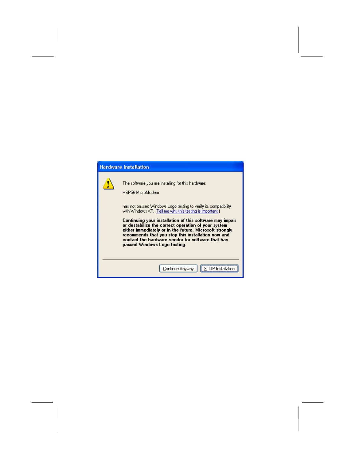
Owing to Microsoft’s certifying schedule is various to every
supplier, we might have some drivers not certified yet by
Microsoft. Therefore, it might happen under Windows XP that a
dialogue box (shown as below) pop out warning you this software
has not passed Windows Logo testing to verify its compatibility
with Windows XP. Please rest assured that our RD department has
already tested and verified these drivers. Just click the “Continue
Anyway” button and go ahead the installation.
II

Mainboard User’s Manual
Table of Contents
Trademarks..............................................................................I
Chapter 1: Introduction...................................................................1
Key Features...........................................................................2
Package Contents....................................................................5
Static Electricity Precautions..................................................6
Pre-Installation Inspection......................................................6
Chapter 2: Mainboard Installation..................................................7
Mainboard Components..........................................................8
I/O Ports..................................................................................9
Install A CPU..........................................................................9
Install Memory......................................................................10
Setting Jumper Switches.......................................................12
Install the Mainboard............................................................13
Optional Extension Brackets.................................................14
Install Other Devices............................................................15
Expansion Slots....................................................................17
Chapter 3: BIOS Setup Utility......................................................19
Introduction..........................................................................19
Running the Setup Utility.....................................................20
Standard CMOS Setup Page.................................................21
Advanced Setup Page...........................................................22
Power Management Setup Page............................................24
PCI / Plug and Play Setup Page............................................25
Load Optimal Settings..........................................................26
Load Best Performance Settings...........................................26
Features Setup Page..............................................................26
CPU PnP Setup Page............................................................28
Hardware Monitor Page........................................................29
Change Password..................................................................29
Exit.......................................................................................30
Chapter 4: Software & Applications.............................................31
Introduction..........................................................................31
Installing Support Software..................................................31
Auto-installing under Windows 98.......................................34
III

Mainboard User’s Manual
I

1: Introduction
Chapter 1
Introduction
This mainboard has a Socket-462 processor socket for the AMD
K7 type of processors. You can install any of these processors on
this mainboard. This mainboard supports front-side bus speed of
200/266MHz.
This mainboard uses SiS 740 chipset that supports a DDR
interface, Ultra DMA 33/66/100 function and remarkably high
system performance under all types of system operations. This
mainboard has a built-in AC97 Codec, providing an AMR (Audio
Modem Riser) slot to support Audio and Modem application, and a
built-in 10BaseT/100BaseTX Network Interface. This mainboard
has the e bedded 256-bit 3D AGP Graphics Accelerator with
64MB frame buffer, supporting AGP 4X 266MHz mode up to
2GB/s bandwidth, which provides a direct connection between the
graphics sub-system and memory so that the graphics do not have
to compete for processor time with other devices on the PCI bus. In
addition, this mainboard has an extended set of ATX I/O Ports
including PS/2 keyboard and mouse ports, two USB ports, a
parallel port, one serial port and one GA port. Connecting the
Extended USB Module to this mainboard can add two extra USB
ports.
This mainboard has all features you need to develop a powerful
multimedia workstation. The board is Micro ATX size and has
power connectors for an ATX power supply.
1

Mainboard User’s Manual
Key Features
The key features of this mainboard include:
Socket-462 Processor Support
Supports AMD Athlon XP/Athlon/Duron processors
Supports 200/266 MHz Front-Side Bus
Processors are automatically configured using firmware and a
synchronous Host/DRAM Clock Scheme.
Memory Support
Two 168-pin DIMM slots for SDRAM memory modules
Two 184-pin DIMM slots for DDR memory modules
Support SDRAM up to 133 MHz /DDR up to 266 MHz
memory bus
Maximum installed memory is 2GB
Notice: ou can NOT use SDRAM and DDR simultaneously.
GA
Embeded 256-bit 3D AGP Graphics Accelerator with
64MB frame buffer
Supports AGP 4X 266 MHz mode up to 2GB/s bandwidth
Supports 333MHz true-colorm RAMDAC, resolution up to
2048 x 1536 x 16 bpp NI
Supports AGP Rev. 2.0 Spec. Compliant
Expansion Slots
One AMR slot for a special audio/modem riser card
Three 32-bit PCI slots for PCI 2.2-compliant bus interface
Onboard IDE channels
Primary and Secondary PCI IDE channels
Support for PIO (programmable input/output) modes
Support for Multiword DMA modes
Support for Bus Mastering and Ultra DMA 33/66/100
modes
2

1: Introduction
Power Supply and Power Management
ATX power supply connector
Meets ACPI 1.0b and APM 1.2 requirements, keyboard
power on/off
Supports Suspend, Shutdown, Wake on LAN, Wake on
Modem, Wake on Alarm, Interrupt Wake-up from
Keyboard/Mouse
AC97 Codec
Compliant AC97 2.1 specification
Supports 18-bit ADC (Analog Digital Converter) and DAC
(Digital Analog Converter) as well as 18-bit stereo full-
duplex codec
Built-in Ethernet LAN
Built-in 10BaseT/100BaseTX Ethernet LAN
LAN controller integrates Fast Ethernet MAC and PHY
compliant with IEEE802.3u 100BASE-TX, 10BASE-T and
ANSI X3.263 TP-PMD standards
Compliant with ACPI 1.0 and the Network Device Class
Power Management 1.0
High Performance provided by 100Mbps clock generator
and data recovery circuit for 100Mbps receiver
Onboard I/O Ports
Built-in Multi-threaded IO Link Delivering 1.2GB/s
Provides PC99 Color Connectors for easy peripheral device
connections
Floppy disk drive connector with 1Mb/s transfer rate
One serial port with 16550-compatible fast UART
One GA port
One parallel port with ECP and EPP support
Two USB ports and optional two USB ports module
Two PS/2 ports for keyboard and mouse
One infrared port connector for optional module
3

Mainboard User’s Manual
Hardware Monitoring
Built-in Hardware Monitor circuit supports Thermal, Power
and Fan Speed monitor
Onboard Flash ROM
Supports 2MB Flash Rom on board, provides complete
Advance Configuration Power Interface(ACPI) and Legacy
PMU
Supports Ultra DMA 66/100 and fully compliant with
PC’97 and PC 98 Spec.
Bundled Software
PC-Cillin2000 provides automatic virus protection under
Windows 95/98/NT/2000
MediaRing Talk provides PC to PC or PC to Phone
internet phone communication
3Deep delivers the precise imagery and displays accurate
color in your monitor
WinDVD2000 is a D D playback application (optional)
Recovery Genius 21st V5.0 provides the function to
recover, reserve and transfer hard disk data.
CD Ghost is the software stimulating a real CD-ROM to
perform equivalent function.
Language Genius 21st is the software to provides learning
tools of language and singing.
Dimensions
Micro ATX form factor (24.5cm x 24.5cm)
4

1: Introduction
Package Contents
Attention: This mainboard series consists of two models,
M841LR (LAN Ready) and M841 (without LAN).
Please contact your local supplier for more information about your
purchased model. Each model supports different specification
listed as below:
Model Specification
M841LR Onboard LAN PHY(U15) and LAN (RJ45)
connector
M841 ---
Your mainboard package ships with the following items:
The mainboard
This User’s Guide
1 UDMA/66 IDE cable
1 Floppy disk drive cable
Support software on CD-ROM disk
Optional Accessories
You can purchase the following optional accessories for this
mainboard.
Extended USB module
AMR v.90 56K Fax/Modem card
5

Mainboard User’s Manual
Static Electricity Precautions
Static electricity could damage components on this mainboard.
Take the following precautions while unpacking this mainboard
and installing it in a system.
1. Don’t take this mainboard and components out of their original
static-proof package until you are ready to install them.
2. While installing, please wear a grounded wrist strap if
possible. If you don’t have a wrist strap, discharge static
electricity by touching the bare metal of the system chassis.
3. Carefully hold this mainboard by its edges. Do not touch those
components unless it is absolutely necessary. Put this
mainboard on the top of static-protection package with
component side facing up while installing.
Pre-Installation Inspection
1. Inspect this mainboard whether there are any damages to
components and connectors on the board.
2. If you suspect this mainboard has been damaged, do not
connect power to the system. Contact your mainboard vendor
about those damages.
6

2: Mainboard Installation
Chapter 2
Mainboard Installation
To install this mainboard in a system, please follow the instructions
in this chapter:
Identify the mainboard components
Install a CPU
Install one or more system memory modules
erify that all jumpers or switches are set correctly
Install the mainboard in a system chassis (case)
Connect any extension brackets or cables to connecting
headers on the mainboard
Install other devices and make the appropriate connections to
the mainboard connecting headers.
Note:
1. Before installing this mainboard, make sure jumper JP1 is
under Normal setting. See this chapter for information about
locating JP1 and the setting options.
2. Never connect power to the system during installation;
otherwise, it may damage the mainboard.
7

Mainboard User’s Manual
Mainboard Components
Use the diagram below to identify the major components on the
mainboard.
Note: Any jumper on your mainboard that do not appear in
the illustration above is for testing only.
8
2: Mainboard Installation
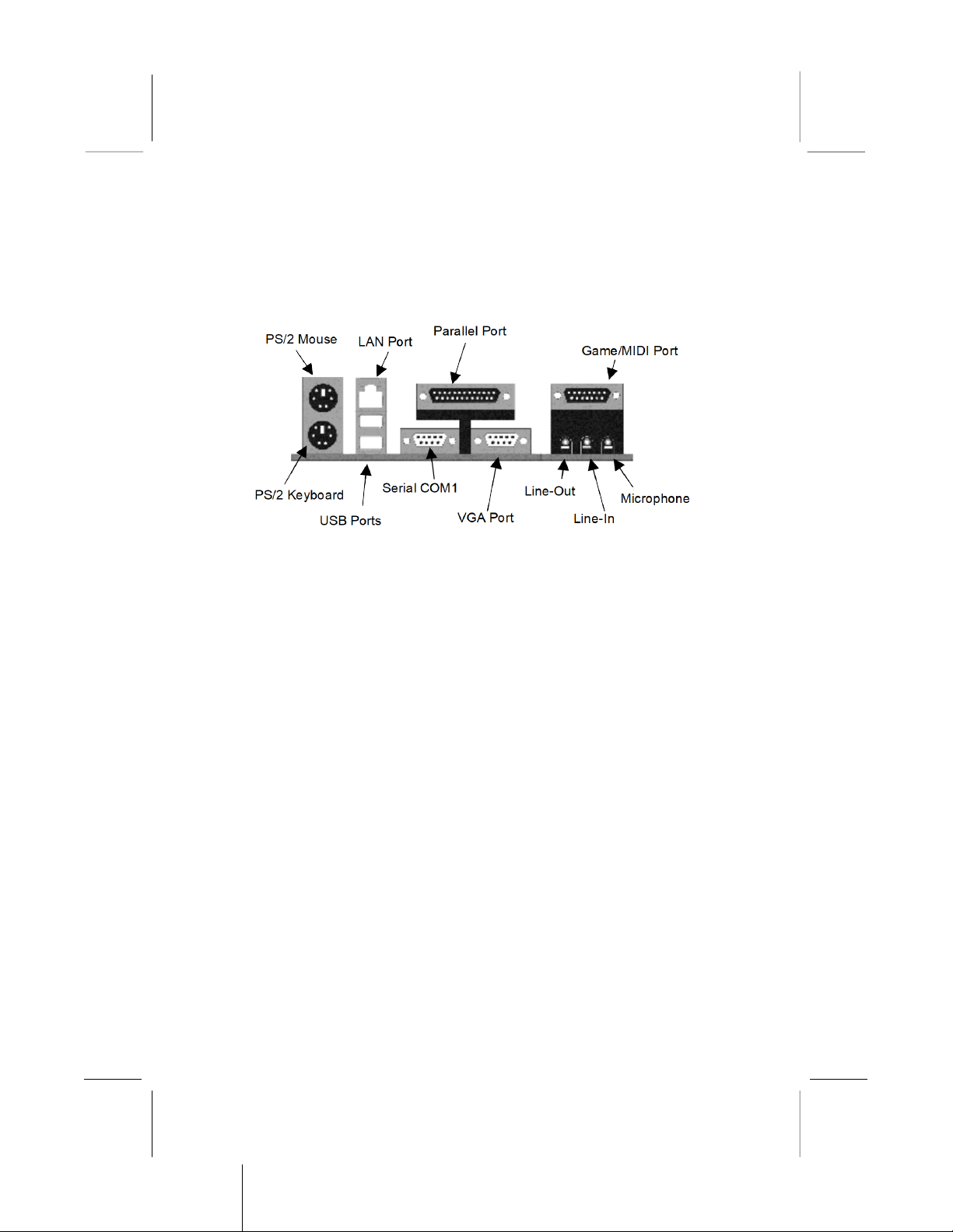
I/O Ports
The illustration below shows a side view of the built-in I/O ports
on the mainboard.
Install CPU
This mainboard has a Socket-462 that supports AMD K7
processors.
To ensure reliability, ensure that your processor has a
heatsink/cooling fan asse bly.
Do not try to install a Socket-370/Socket-7 processor in the
Socket-462. A Socket-370/Socket-7 processor such as the PPGA
Celeron, FCPGA Pentium-III, Pentium-MMX, or the AMD K5/K6
does not fit in the Socket-462.
The following list indicates these processors are currently
supported by this mainboard.
Athlon XP: 1500+ ~ 1900+; FSB: 266 MHz
Athlon/Duron: 500M ~ 1.4GHz; FSB: 200 MHz, 266 MHz
9
Mainboard User’s Manual
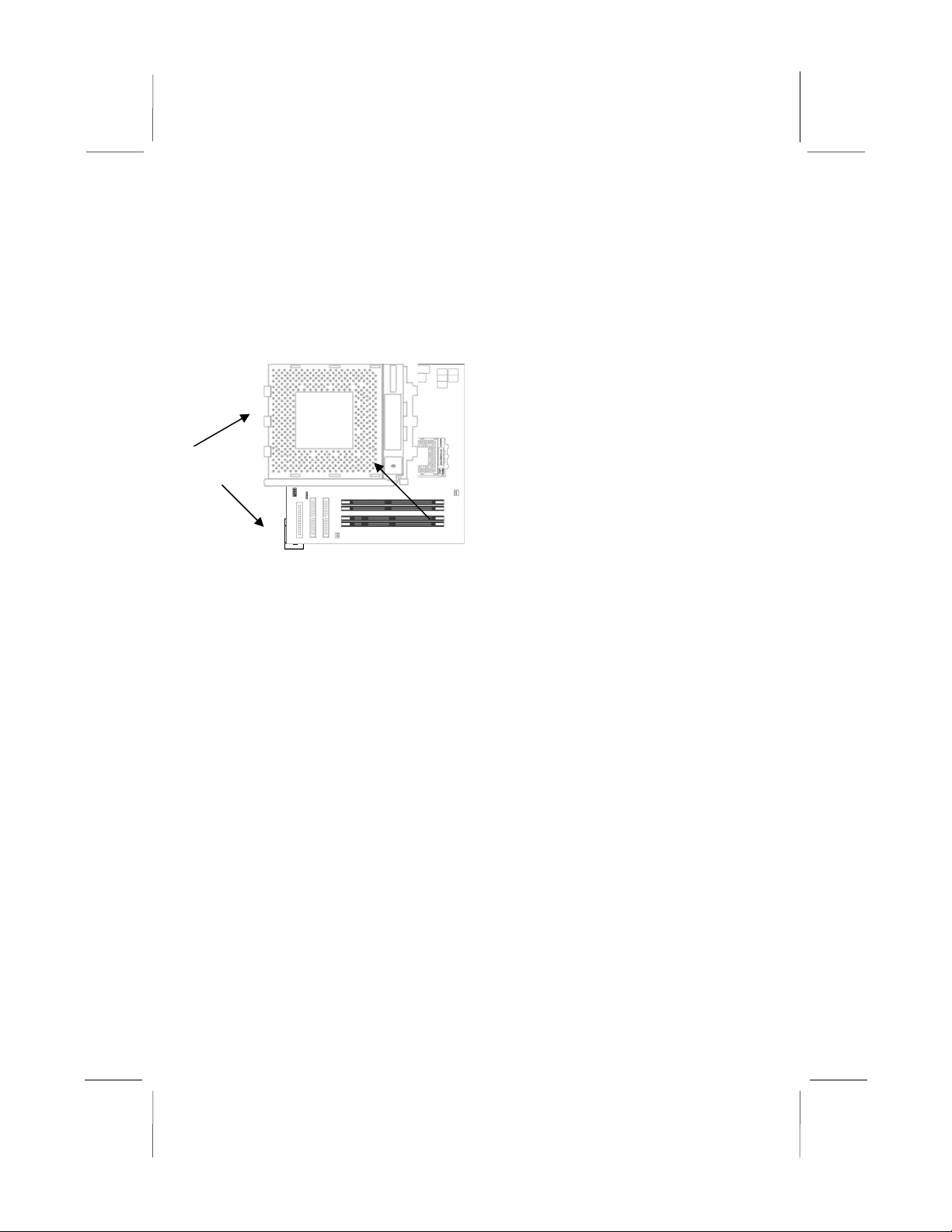
Installing a Socket-462 Processor
Install a processor into the ZIF (Zero Insertion Force) Socket-462
on the mainboard.
1. Locate the Socket-462 and CPUFAN. Pull the locking lever
out slightly from the socket and raise it to the upright position.
2. On the processor, identify the Pin-1 corner by its beveled edge.
3. On the Socket-462, identify the Pin-1 corner. The Pin-1 corner
is at the top of the locking lever when it locked.
4. Match the Pin-1 corners and insert the processor into the
socket. No force is required and the processor should drop into
place freely.
5. Swing the locking lever down and hook it under the catch on
the side of the socket. This secures the CPU in the socket.
6. All processors should be installed with a combination heatsink/
cooling fan, connect the cable from the fan to the CPU fan
power connector CPUFAN.
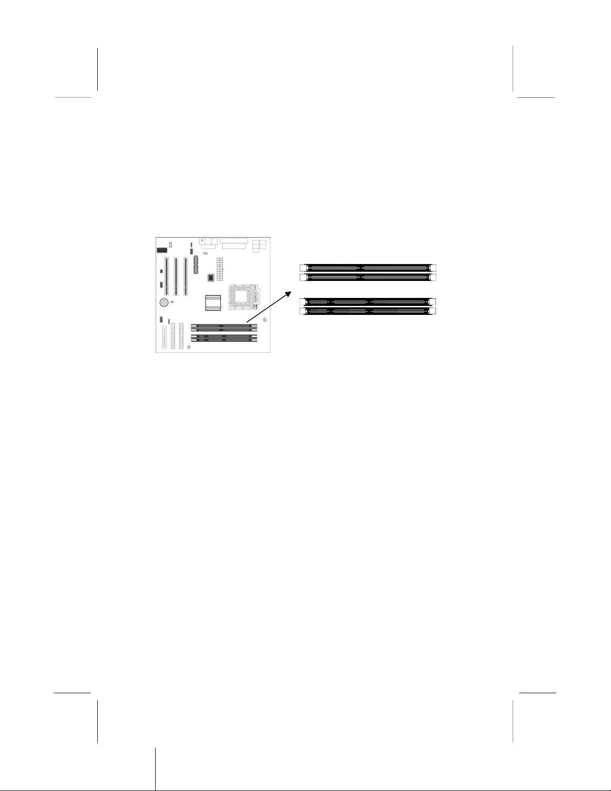
Install Memory
The mainboard has two 168-pin/184-pin DIMM sockets for
SDRAM/DDR (Double Data Rate) SDRAM system memory
modules. You must install at least one memory module in order to
work out the mainboard, either SDRAM or DDR SDRAM, but
you can not use the si ultaneously.
10
CPUFAN
Socket-462
Pin-1 Corner
2: Mainboard Installation
DDR SDRAM provides 800 MBps or 1 GBps data transfer
depending on whether the bus is 100 MHz or 266 MHz. It doubles
the rate to 1.6 GBps and 2.1 GBps by transferring data on both the
rising and falling edges of the clock. DDR SDRAM uses additional
power and ground lines and requires 184-pin 2.5 unbuffered
DIMM module reather than the 168-pin 3.3 unbuffered DIMMs
used by SDRAM.
For this mainboard, the maximum memory size is 2GB.
The edge connectors on the memory modules have cut outs, which
coincide with spacers in the DIMM sockets so that memory
module can only be installed in the correct orientation.
To install a module, push the retaining latches at either end of the
socket outwards. Position the memory module correctly and insert
it into the DIMM socket. Press the module down into the socket so
that the retaining latches rotate up and secure the module in place
by fitting into notches on the edge of the module.
11
SDR1
SDR2
DDR1
DDR2

Mainboard User’s Manual
Setting Jumper Switches
Jumpers are sets of pins which can be connected together with
jumper caps. The jumper caps change the way the mainboard
operates by changing the electronic circuits on the mainboard. If a
jumper cap connects two pins, we say the pins are SHORT. If a
jumper cap is removed from two pins, the pins are OPEN.
Jumper JP1: Clear CMOS Memory
This jumper can clear the contents of the CMOS memory. You may
need to clear the CMOS memory if the settings in the Setup Utility
are incorrect and prevent your mainboard from operating. To clear
the CMOS memory, disconnect all the po er cables from the
mainboard and then move the jumper cap into the CLEAR setting
for a fe seconds.
Function Jumper Setting
Clear CMOS Memory Short Pins 1-2
Normal Operation Short Pins 2-3
12
1
JP1

1
2: Mainboard Installation
Install the Mainboard
Install the mainboard in a system chassis (case). The board is an
ATX size mainboard with a twin-tier of I/O ports. You can install
this mainboard in an ATX case. Ensure that your case has an I/O
cover plate that matches the ports on this mainboard.
Install the mainboard in a case. Follow the instructions provided by
the case manufacturer using the hardware and internal mounting
points on the chassis.
Connect the power connector from the power supply to the
ATX_PWR connector on the mainboard.
If there is a cooling fan installed in the system chassis, connect the
cable from the cooling fan to the SYSFAN fan power connector on
the mainboard.
Connect the cable from the PC speaker to the SPK1 header on the
mainboard.
Connect the case switches and indicator LEDs to the SW1 header.
If there are a headphone jack or/and a microphone jack on the front
panel, connect the cables to the AUDIO1 header on the mainboard.
See the illustrations below for the guide to the SW1 and AUDIO1
headers pin assignments.
13
SYSFAN
ATX_PWR
AUDIO1
SP 1
1
SW1
Suspend LED P2-4HDD LED P1-3
Reset Switch P5-7 Power Button P6-8
1 2
AUDIO1
MIC 1
MIC-P 3
FPOUT-R 5
NC 7
FPOUT-L 9
2 GND
4 VCC
6 RET-R
8 Key
10 RET-L
SW1
1

Mainboard User’s Manual
Optional Extension Brackets
For this mainboard, you can also obtain a USB module extension
bracket for more USB ports. Install them by following the steps
below.
Note: All the ribbon cables used on the extension brackets have a
red stripe on the Pin-1 side of the cable.
Extended USB Module
This module bracket has two USB ports for more USB devices
(USB port 3-4).
1. Locate the USB2 header on the mainboard.
2. Plug the bracket cable onto the USB2 header.
3. In the system chassis, remove a slot cover from one of the
expansion slots and install the extension bracket in the
opening. Use the screw that held the slot cover to secure the
extension bracket in the chassis.
14
USB2
1

2: Mainboard Installation
Install Other Devices
Install and connect any other devices in the system following the
steps below.
Floppy Disk Drive
The mainboard ships with a floppy disk drive cable that can
support one or two drives. Drives can be 3.5” or 5.25” wide, with
capacities of 360K, 720K, 1.2MB, 1.44MB, or 2.88MB.
Install your drives and connect power from the system power
supply. Use the cable provided to connect the drives to the floppy
disk drive connector FDC.
IDE Devices
IDE devices include hard disk drives, high-density diskette drives,
and CD-ROM or D D-ROM drives, among others.
The mainboard ships with an IDE cable that can support one or
two IDE devices. If you connect two devices to a single cable, you
must configure one of the drives as Master and one of the drives as
Slave. The documentation of the IDE device will tell you how to
configure the device as a Master or Slave device. The Master
device connects to the end of the cable.
Install the device(s) and connect power from the system power
supply. Use the cable provided to connect the device(s) to the
Primary IDE channel connector IDE1 on the mainboard.
If you want to install more IDE devices, you can purchase a second
IDE cable and connect one or two devices to the Secondary IDE
channel connector IDE2 on the mainboard. If you have two
devices on the cable, one must be Master and one must be Slave.
15
IDE1
1 1
IDE2
FDC
1

Mainboard User’s Manual
Internal Sound Connections
If you have installed a CD-ROM drive or D D-ROM drive, you
can connect the drive audio cable to the onboard sound system.
On the mainboard, locate the two 4-pin connectors CD_IN1 and
CD_IN2. There are two kinds of connectors because different
brands of CD-ROM drives have different kinds of audio cable
connectors. Connect the cable to the appropriate connector.
Infrared Port
You can connect an infrared port to the mainboard. You can
purchase this option from third-party vendors.
1. Locate the infrared port IR1 header on the mainboard.
2. If you are adding an infrared port, connect the ribbon cable
from the port to the IR1 header and then secure the port to an
appropriate place in your system chassis.
16
CD_IN1
1
IR1
NC
+5V 3
IRTX 5
2 Key
4 GND
6 IRRX
CD_IN2
This manual suits for next models
1
Table of contents
Other IBM Motherboard manuals


