IBM Low Power 667Mhz Panel PC PPC-1510PT User manual

-1 -
User’s Manual
PPC-1510PT
15.1” TFT Low Power 667Mhz Panel PC
-2 -
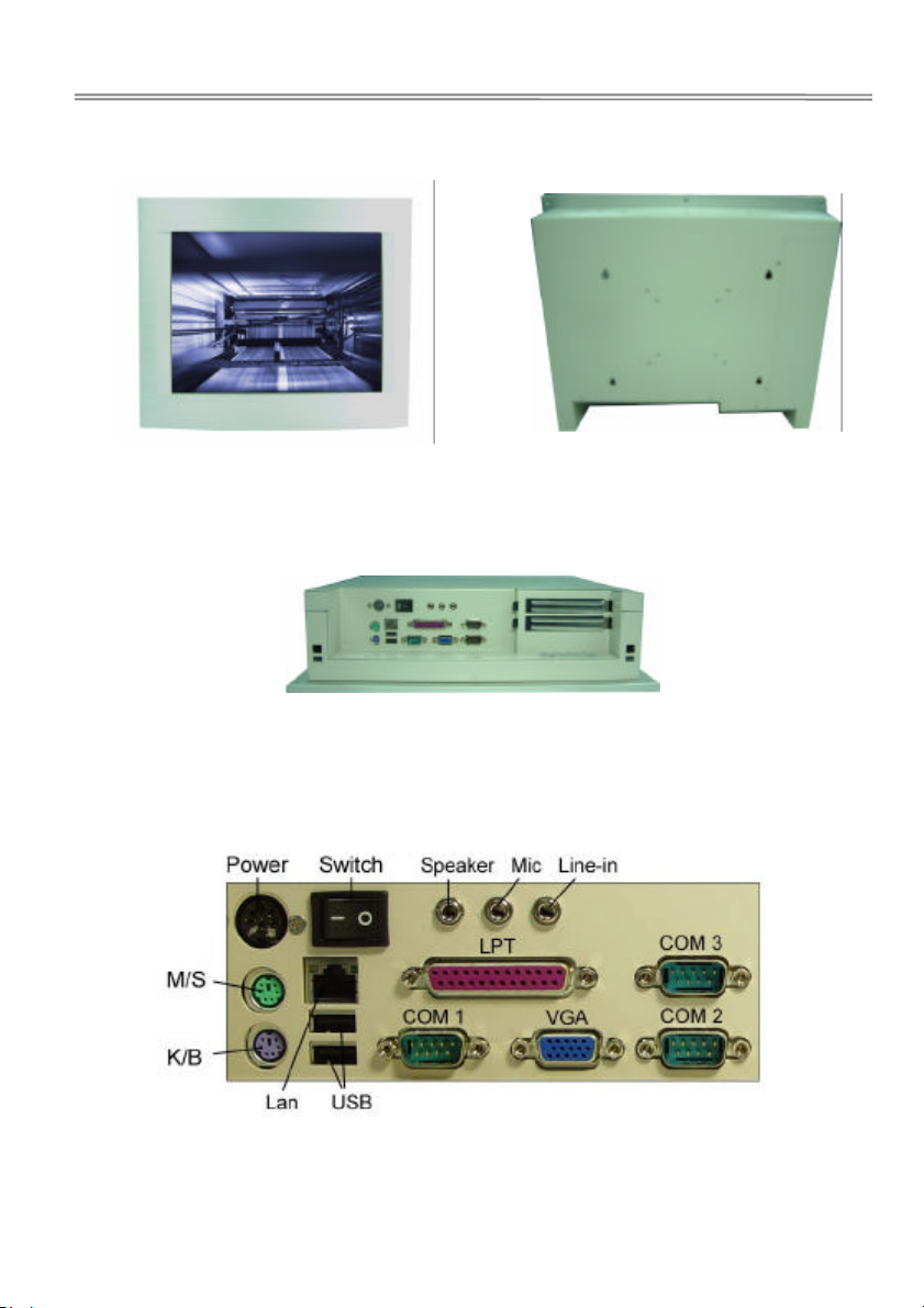
Ⅰ.Pictures of PPC-157T
Silver (Stainless Steel Color) VESA-75
VESA-100
I/O ports

-3 -
Ⅱ.Panel PC Specifications
◆Display-15.1"colorTFT flat panel
◆Display Type -TFT LCD panel
◆Luminance –200-250 cd/m2 brightness luminance
◆CPU -P-III equivalent Low power 667Mhz CPU L1 & L2 cache built on CPU
◆System Chipset -Twister-T , VIA VT8606 , 82C686B
◆Front Bezel -Thick10mmAluminum-alloyhairlineanodizingtreatmentfrontbezel
◆Housing & Wall-mounting -Rugged1.2mmthicksteelmetalwithwhitepaintingVESA–75and
VESA-100 compliant
◆Surface Treatment of Front Panel -Super high-endhairlineanodizingtreatment,color
◆Standard Colors -Stainless Steel silver color
◆Front Panel Protection -MeetNEMA 4, 12 and IP65, 56 water resistant EIA standard
◆SystemMemory -OneslimsizeCD-ROM, 24x speed built in
◆CD-ROM (optional) -OneslimsizeCD-ROM,24xspeedbuiltin
◆HDD (optional) –10-20slimsizeHDD
◆Disk On Module (optional) -SupportDOMupto512MB
◆DiskOnChip(optional) -SupportM-System’sDOC upto288MB
◆Serial ports -4x COMs ( 3 x RS232 port ,1 xRS232/422/485 port)
◆USB -2 x USB ports and IrDA pin header on board
◆Parallel Port -LPT port for Printer connection.
◆Keyboard and Mouse -OnePS/2KB/Mouse port
◆Audio I/O -Microphone, Speaker, Line-in
◆Network Interface Controller Chipset -Realtek8139C,support 10/100 Mbp,auto-negotiation ,auto-switch
LAN
◆VGA -Display Controller Chipset -S3Savage4,supportAGP4XLCD/2-channel LVDS,TFT,
DSTN LCD/CRT with 32MB share Video memory,3D/2Dsupport
◆DVD MPEG-2-support DVD video playback
◆Touch Panel (Optional) -Long-life 6-wireresistive Touch screen
◆Power Requirements -Long-life 6-wireresistiveTouch screen
◆Dimension ( WxHxD) -
◆Operating Temperature -0 to 55°C (32 to 131°F)

-4 -
Ⅲ. Power Supply
Input : 100-240VAC ~ 2A 50/60Hz
DC Output : +5V/7A, +12V/1.5A
-12V/0.3A, +5Vsb/0.75A
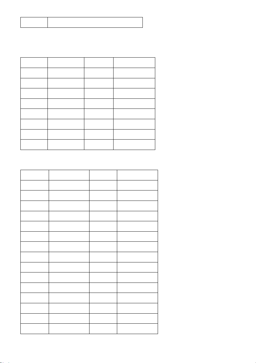
Ⅳ. NAGASAKI Panel PC Comparison table
Model no. SBC CPU Power
PPC-64T NASA-6820 667Mhz onboard AC-DC Adaptor
PPC-70T MS-2100 300Mhz onboard AC-DC Adaptor
PPC-106T NASA-6109 667Mhz onboard AC-DC Adaptor
PPC-106T-DC NASA-6109 667Mhz onboard DC-DC Adaptor
PPC-107PT NASA-6109 667Mhz on board AC-DC Adaptor
PPC-107PT-DC NASA-6109 667Mhz on board DC-DC Power
PPC-127T NASA-6109 667Mhz onboard AC-DC Adaptor
PPC-127T-DC NASA-6109 667Mhz onboard DC-DC Adaptor
PPC-128HT NASA-
6104LL
800Mhz AC-DC Adaptor
PPC-129PT NASA-6109 667Mhz onboard AC-DC Adaptor
PPC-129PT-DC NASA-6109 667Mhz on board DC-DC Adaptor
PPC-156T NASA-6102 667Mhz onboard AC-DC Power
PPC-157T NASA-6109 667Mhz onboard AC-DC Adaptor
PPC-157T-DC NASA-6109 667Mhz on board DC-DC Adaptor
PPC-158T NASA-6111 667Mhz onboard AC-DC Power
PPC-159T NASA-6101 667Mhz onboard AC-DC Power
PPC-1510PT NASA-6109 667Mhz onboard AC-DC Power
PPC-1510PT-DC NASA-6109 667Mhz on board DC-DC Adaptor

-5 -
Ⅴ. Touch Panel
1.Application
2. Warranty
3. Features
4. Characteristics
4.1Usable Temperature Range
4.2StorageTemperature Range
4.3Input Method
5. Electrical Specifications
5.1Linearity
5.2Insulation Resistance
5.3Chattering Time
6. Mechanical Specifications
6.1OperatingForce (with pen)
6.2Surface Hardness
7. Optical Specifications
7.1Light Transmittance
8. Reliability
8.1Line drawing operation
8.2Pen hitting operation
9. Environment Durability Performance
9.1High Temperature Test
9.2LowTemperatureTest
9.3Humidity Test
9.4Thermal ShockTest
9.5Resistanceto Chemical
10. Quality Level
10.1Inspectioncondition
10.2Criterion
10.3Glass Fragment
10.4Newton ring

-6 -
11. Cautions
1.Application :Thisspecification is applied to 6wireTouchPanel.
2.Warranty: TOUCH PANEL products manufactured tothisspecification shall be capable of meetingall
characteristicsfora minimum period of 12monthsthedate of shipping from NAGASAKIIPCwhen stored or used as
specifiedundernormal conditions within the contents of these sheets. If TOUCH PANEL productsarenotstored or
usedasspecified herein, it will bevoidthe 12 months warranty.
3.Features
Type :AnalogResistiveTypeTouchPanel
InputMode :PolyesterPen orFinger
Structure :Film----- ITO Film Glass----ITOGlass
4.Characteristics
4.1OperatingTemperature Range : From–20 to60 (Humidity90%RHorlower,nodewconditionshallbe℃ ℃
acceptable)
4.2StorageTemperature Range : From–30 to70℃ ℃
(Humidity90%RH or lower, no dewconditionshall be acceptable)
4.3Input Method:
(1)withPolyester Pen:
Operationand measurement with a penmustbe carried out under thefollowing trip condition:
Material:Polyester Tip:SR0.8millimeter
(2)with Finger:
Operationandmeasurement with a finger must be carriedoutunderthe
Material:Siliconrubber (Hardness: 60º Hs) Tip:SR12.5 millimeter
5.Electrical Specifications
5.1Linearity Direction:± 1.5% or less (with calibrationcontroller)
5.2Insulation Resistance:20MOor more@DC 25V
5.3ChatteringTime :10 millisecond orless @ 100KO
6.MechanicalSpecifications Item No. ItemRatingsTestMethods & Condition
6-1Operating Force(withPolyester PenSR 0.8)
Accordingtoapplicable product specification Less than150g Using a loadcell with a PolyesterPen conforming to the
specificationsset forth in item 4.3(1) attached to itstip, apply a vertical loadwithinthe validarea.
Usingthemeasurement circuit illustrated indiagram 6-1below,take the gauge value whenthevoltage value 4.5V or
greateras the pressure load value.
6-2Surface Hardness : 2H orHigher JIS-K5400

-7 -
7.OpticalSpecifications
7.1LightTransmittance(TotalTransmittance):More than 78%(Measuringapparatus:Haze meter-madeby
BYK-Gardner
Type:Haze–Gard-plus 4726 Illuminant:CIE-AStandard:ASTM D 1003)
8.ReliabilityItem No. Item RatingsTestMethods& Condition
8-1Line drawing operation 1,000,000 times of drawingRequirementin paragraph 5 and6Drawingmustoccurin
followingmanner at any point withinanAction area.
1)Testing equipment:Pen plotter
2)Testing load / force:2.5 N
3)Sliding speed:200 mm / second
4)Tipprobe:Polyester Pen asdefined in sub-paragraph4-3(1)
8-2Pen hitting operation 5,000,000hits with a penRequirement in paragraph 5and 6Hitsmustbemadeinthe
followingmanner at any pointwithinat effective area.
1)Testing equipment:Pen plotter
2)Testing load:2.5 N
3)Pressspeed:3hits / second
4)Tipprobe:PolyesterPen as defined insub-paragraph 4-3(1)
9.Environment Durability PerformanceItemNo. Item Ratings Test Methods & Condition
9-1HighTemperatureTest Requirement inparagraph 5 and 6 Putit in a vesselat the conditionof70±1and45℃
±1%humidityrelative for 120 hours. Moreoverletit alone for 24 hours ormorein a room temperature andmeasureit.
9-2LowTemperatureTest Requirement in paragraph5 and 6 Putit in avessel at the conditionof –30±1for120℃
hours.Moreover, let it alone for24hours or more in aroomtemperature and measure it.
9-3Humidity Test Requirementinparagraph 5 and 6Leaveinanenvironmentof60±1and90±1%relative℃
humilityfor120 hours and then perform measurementsafterleaving at room temperature for24 hours
9-4Thermal Shock Test Requirement inparagraph 5 and 6Put it in avessel at theconditionof70±1for30℃
minutes and then –30±1for30minutesandhisprocessisrepeatedby10cycles.Moreoverletitalonefor24ho℃urs
ina room temperature and measureit.
9-5Resistance to chemicals (Surface hard coating) Noabnormalityin external appearance Lightly wipe thesurface
withmethyl alcohol, artificial perspirationorhousehold cleanser (neutral).
10.QualityLevel
10.1 Inspection ConditionThe inspection shall beperformedby using Back light150-300 cd/m2 ,1000-1400Lux
(naturallight)underthesurfaceof sensor. The panel shallbe position sensors from 45cmformeyes and an.
Angle30 degree (15~45), 15 secondviewing time.

-8 -
10.2CriterionThe followings areappliedtoviewing area The item 10.2 (1,2,3,4) should apply totheVA(view area)
unlessnone VA affect electricalperformance
(1)Scratch
Width0.1mmandlength20mm≦ ≦ :Accept.
Width> 10 mm orLength> 20mm :Reject
(2)Granular foreign object
Diameter0.5mm≦:Acceptable 0.5mm <Diameter:Unacceptable
(3)Linear foreign object (fiber)
Width0.05andLength5mm≦ ≦ :Accept Width0.05andLength≧>5mm:Unacceptable
(4)Blistering(Puffiness, Baggy) Check throughany0.5millimeter gauge whether aTouchPanelsurfacefilmdoesnot
contactameasuringface.0.5mmgauge 0.5mm Tablet
10.3Glass Fragment
(1)CornerFragmenta2mm≦;b2mmand≦(c:breakheightt≦): Itis acceptable two(t:GlassThickness)
(2)SideFragmenta3mm,b2.0mmandc1/2t≦ ≦ ≦ :acceptable
fiveandintervalof faults is 20mm minimum everyside. (t:GlassThickness)
10.4Newton ring
Diameter35mm≦,Acceptable
Passifdefect that fails size cannot be seenwhenheld in front of colors programonmonitor.
11.CautionsItemNo. Subject Note
11.1Storage1)StoreTouchPanel at the stated temperatureand humidity range.
2)StoreTouchPanel with original packing.
3)DonotexposeTouch Panel directly to the sun
11.2Unpacking1) Do not hold FPC/ Copper tail to take TouchPanel out of the package.
2)Open the package after checking “UP / DOWN”mark.
3)Donotput the heavy shock and stress onTouchPanel.
11.3Handling1)Weargloves at handling to prevent stains on TouchPanel or injury by thesharp edge of touchglass.
2)Do not hold FPC/ Copper while handling TouchPanel.
3)DonotpileTouchPanels and put heavy matter on TouchPanel.
4)Donot add any stress ontouch film.
5)Use dry cloth or softclothwith alcohol, neutral detergentorone with ethanol atcleaningin case of dirt.
6)Do not use organicsolventsexcept alcohol. 11.4Assembling 1)Avoid excessive force on theTouchPanel.
7)Donotgiveunnecessary strain to the FPC / Copper tail while assembling.

-9 -
Ⅵ. NASA-6109 User’s Manual
Copyright Notice
Thecontentof this manual has been checkedforaccuracy.The manufacturer assumes no responsibility forany
inaccuraciesthatmaybecontainedinthismanual. Themanufacturerreservestherighttomakeimprovementsor
modificationtothe this document and/ortheproduct at any time withoutpriornotice. No part of this document may be
reproduced,transmitted,photocopied or translated into any language,inany form or by any means,electronic,
mechanical,magnetic, optical or chemical, without theprior written permissionofthemanufacturer.VIAisregistered
trademarkofVIATechnology Incorporation VT82C686A mayonlybeused to identify products of VIATechnology
Realtek isregistered trademark of Realtek TechnologiesInc.Multiscan isatrademarkofSonyCorpofAmericaIBM,
EGA,VGA, PC/XT, PC/AT, OS/2 and PS/2 areregistered trademarks of InternationalBusiness MachinesCorporation
Intelisaregistered trademark of Intel Corporation Plugand Play is registeredtrademarks of Intel CorporationMicrosoft,
Windowsand MS-DOS are trademarks ofMicrosoft Corporation AwardisatrademarkofAward Software Inc. PCIisa
registeredtrademark of PCI Special InterestGroupOther product
namesmentionedherein are used for identificationpurposeonly and may be trademarksand/or registered trademarks
oftheirrespective companies.
Installation Notice
Themanufacturerrecommends using a grounded plug toensureproper motherboard operation. Care should beused
inproper conjunction with a grounded powerreceptacletoavoid possible electrical shock. All integratedcircuitsonthis
motherboardare sensitive to static electricity. To avoid damaging componentsfrom electrostatic discharge, pleasedo
notremove the board from the anti-static packing before discharging any static electricityto your body, bywearinga
wrist-groundingstrap.Themanufacturerisnot responsible for any damage tothemotherboarddueto
improperoperation.
Specification
Thismanual covers two differentlayoutmodels, and the respective boardlayoutsare shown in chapter 1-4. Please
refertothefollowingdescription to make sure which model on hand beforeusing.
MODEL NASA-6109
SystemChipset VIAPM133 , VT8601/VT686B

-10 -
CPUSupporting EmbeddedVIAEDENESP5000(533MHz)or VIA c3
800MHzCPU
LANAdapter Realtek8139Cor Intel 82559ER
AudioAdapter *Optional
VGAAdapter Onchip2D/3D Graphic Controllerw/SMA up to8MB
LCDSupporting TFTTTLLCDoptionalLVDS l
ROM-Disk Socket Yes (2-288MB)
TV-Out Optional
I/OPort 4S/2P
IDEInterface U. DMA 33/66/100
DIMMSocket 1
Max.RAMSize 512MB
VGAMemorySize 8MB
WatchDogTimer Optional
AT/ATXPower Yes
USBFeature Yes
BoardSizeFormat 203x146mmSBCFormat
Chapter 1. Introduction
Inorderto cope with the challengesoftheheating issues and demand ofmuchmore diminutive embedded system in
diverseapplication, NASA-6109 series CPU boardsprovides the ultimate solution by integratingwithVIA’stechnology
lowpower consumptionVIAC3series CPU and VIAEDENfanlessESP series CPU. NASA-6109seriesCPU boards
offerthe assorted functions for variousapplicationssuch as high-end POS systems, kiosks, networkingsystems,
controllingterminals and other embedded systems.
NASA-6109 is a 5.25”SBCuses VIA chipsets built-inVGAandAudiofeatureonboard, support TFT TTL LCDfeature
withLVDS interface as feature option; built-in Realtek 8139XX LAN chipsetwith RJ45 Jack for 10BaseT/ 100BaseT.The
option ofIntel 82559ERchip is also provided for theLANsupport. This SBC offers the highestperformancePC
specificationin the industry with embeddedlowpower consumption VIA EDEN fanless ESP seriesCPUESP5000,and

-11 -
withtheoption of the higher performedVIA C3 800MHz CPU. For easier assemblyand betterintegration without
arrangingarray of cables, NASA-6109 provides onboardconnectors with a similarconventionalATX layout.
NASA-6109 providestheoptionofintegratingWatch Dog Timer for ideal unattended terminals. To offerbetterflexibility, it
alsoprovides the options of risercard for PCI orISA expansion through a 188-pinslot.ThisCPUboardis fully compatible
withindustry standards, adding many technicalenhancementsand are fully compatible withthousand of software
applicationsuchasWIN95,98,WINNT3.x / 4.x, WIN 2000, WIN ME, WIN CE (.NET), LINUX, UNIX, Novell…etc. The
controllogicprovides high-speedperformancefor the most advanced multi-user, multitaskingapplicationavailable today.
“Tomorrow’sPC technology is here today”.
1-1. Features
◆NASA-6109,embedded VIA C3 TM, Eden TM, Ezra TMLowPowerEBGA processors.
◆133/100 / 66 MHz CPUFrontSideBus (FSB)
◆DRAMinterface synchronous or pseudosynchronouswith CPU FSB speedof 133 / 100 /66MHz Mixed 1M /2M/
4M / 8M/ 16M /32MxN DRAMs
◆1or 2 DIMM 168 Pin socket supportedup to 512MB or1.0GB
◆3.3VDRAM interface with 5V-tolerantinputs
◆SupportDualchannel UltraDMA-100 /66 / 33 enhanceIDE
◆AC-97 link.
◆On-boardbuilt-in 2 or 4 USB ports.
◆IntegratedSuper-I/Osupport 4 Serial withpower selector and 2parallelports.
◆OptionalRS-422/485 viaCOM2
◆SystemHardwaremonitoring
◆Keyboard/mouse interfaces.
◆RTC/CMOS
◆PCI-2.2 compliant,32 bit 3.3V PCI interfacewith 5V tolerant inputs.
◆33MHz operation on the primary PCIbus
◆188pinexpansion slot for both PCIandISA Bus signals.
◆PC99Hardware Support
◆Watch-Dog-Timer support 1-255secprogrammable.
◆On-boardsupport Realtek or Intel82559/ER 10/100 LAN adapter with RJ-45 port.
◆AGPv1.0compliant
◆IntegratedAGPBus 2D / 3D graphic accelerator.

-12 -
◆Windows95 OSR-2VXDandintegratedWindows98 / NT5 miniport driversupport
◆BIOSshadow at 16KB increment
◆Supports2, 4 and 8 Mbytesof Frame Buffer with sharememory.
◆DirectDrawTMand DirectVideoTM Hardware Support
◆AdvancedMobile Power Management
◆CRTPower Management (VESA™ DPMS)
Optional for Flat Panel Interface ( TTL or LVDS )
Theboard is designed to supportindustrystandard TFT panel via 44pinconnector or LVDS transmitters.The interface
supportsboth 18-bit and 24-bitdisplaymodes.Optionally,an 18+18 panel canbe supported utilizing externallatches.
Optional Features
◆SupportsRS422/RS485interfacewith COM2
◆SupportLVDS LCD panel
◆SupportsAudio function(viaAVCardKit)
◆SupportsTV-Out feature(viaTV-Out adapterKit)
◆SupportWatchDogTimer/POSTcode(WDTonlyfor NASA-6109)
◆SupportBOOT ROM
Ordering information
NASA-6109
1. NASA-6109VLA:Support 1 LAN
2. NASA-6109LVDS:Support1LAN + LVDS
Note: The standard version of NASA-6109 is embedded with VIA EDEN Fanless 533Mhz and 667MHz .
Other option CPUs will be provided upon request.
1-2. Unpacking
Themotherboardcomes securely packaged in a sturdy cardboardshippingcarton. In addition to the User's Manual, the
motherboardpackage includes the following items:
◆NASA-61095.25” SBC / CPU Board
◆HDD/FDDCables
◆TV-Out adapter / cable (Optional)
◆AudioKit (Optional)
-13 -
◆LCDcable (Optional)
◆IDEDriverincludes: Drivers for Windows NT3.x/4.x, Windows 95, 98, 2000,WinMe, Linux, Novell Netware and
AMIFLASH ROM utilities.
◆Driverutilitiesfor on-board VGA drivers,LAN adapter and DOC 2000
Ifanyofthese items are missing or damage,pleasecontactthedealer from whom you purchase themotherboard.
Savetheshipping material and carton in theeventthat you want to ship orstore the board in the future.
Note: Leave the motherboard in its original package until you are ready to install it !
1-3. Electrostatic Discharge Precautions
Makesure you properly ground yourselfbeforehandling the motherboard, orother system components. Electrostatic
dischargecan easily damage the components.
Note:You must take specialprecautionwhen handling the motherboard indryor air-conditioned environments
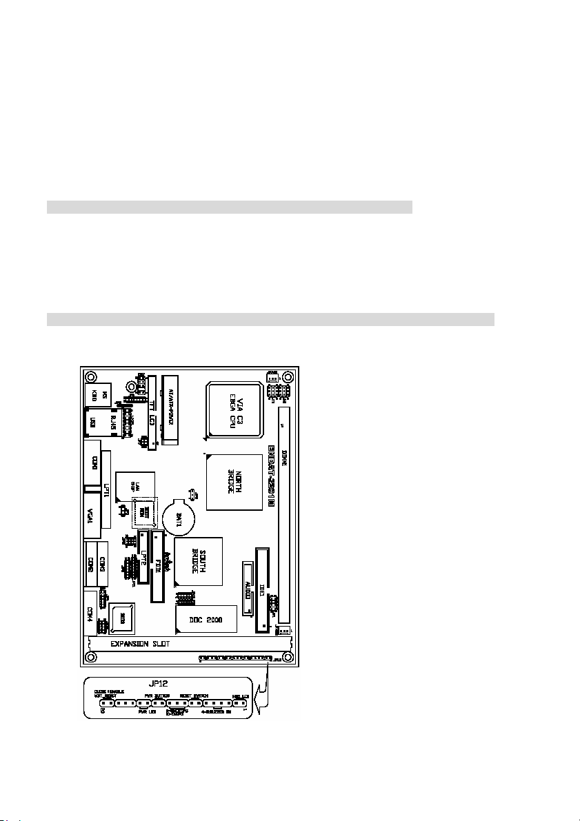
1-4. 5.25” SBC (NASA-6109)

-14 -
Chapter 2. Setting up the 6109 CPU board
Jumpers and Connectors
Jumpers/Connectors Overview:
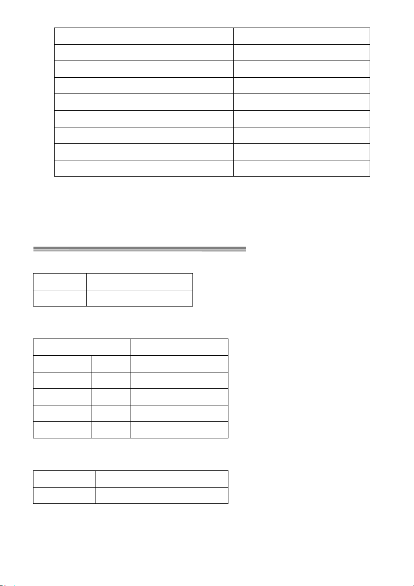
Function Jumpers/Connectors
CoolingFanConnector JFAN1, JFAN2
PowerSupply:PowerGood JP12: Pin9~11
ATXPowerOn/OffSwitch JP12: Pin12~13
AudioPortConnectorCN1
2ndPrinterPort CN4
LANAdapterDisable/Enable JP3
COM1Port CN6
COM2Port CN8
COM3Port CN2
COM4Port CN3
COMPortsPowerSelector(COM1,2,3,4) JP4,JP9
RS232/RS422/RS485Selector(COM2) JP10,JP11
DiskOnChipMemoryAddress JP15
LCD:TFT LCD Panel Connector LCD-CON1
LVDSLCDOutputPort CN5
LVDSVoltageSelector JP5
ClearCMOS JP2
FactorySetting JP1,JP7,JP8,JP13,JP14,JT1,JH1
PS/2KeyboardJack JKBMS
PS/2MouseJack JKBMS
PS/2Mouse/KBPinHeader CN7
IR J1
FDDConnector FDD1
IDE1 IDE1
HeaderforCasePanel JP12
IDE1LED JP12: Pin 1, Pin 2
-15 -
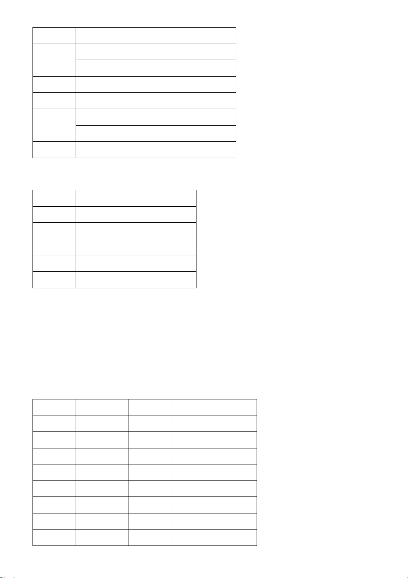
Function Jumpers/Connectors
ExternalSpeaker JP12: Pin3,Pin6
BuzzerOn/Off JP12: Pin4,Pin5
HardwareResetSwitch JP12: Pin7,Pin8
ExternalPowerGood JP12: Pin9,Pin10
InternalPowerGoodJP12: Pin10,Pin11
ATXPowerSupplyOn/OffSwitch JP12: Pin12,Pin13
PowerLED JP12: Pin14,Pin15
WDTFunctionEnable/Disable JP12: Pin19,Pin20
Pleasedouble-check the insertion and orientation oftheLCD cable before applying power:mproperinstallationwill result
inpermanent damage LCD panel.
JP2: CMOS Data Clear:
Pin1-2 * Normal
Pin2-3Clear CMOS Data
JP15: DiskOnChip Memory Address Selector
JP15 MemoryAddress
1-27-80C800H-0C9FFH
1-29-10 0CC00H-0CDFFH
3-47-80DCCCH-0D1FFH
3-49-10 0D400H-0D5FFH
5-67-80D800H-0D9FFH(Default)
JP3: On-board LAN Disable/Enable
Pin1-2Enable On-Board LAN
Pin2-3Disable On-Board LAN

-16 -
JP9 (COM1, 2) / JP4 (COM3, 4) Voltage Selector:
Voltage COM1(JP9)
COM2(JP9)
COM3(JP4)
COM4(JP4)
+12V(dc)
1-27-81-27-8
R.I. 3-49-10 3-49-10
+5V(dc) 5-611-12 5-611-12
JP10, JP11: RS232 / 422 / 485 Selector for COM2
TYPE JP10 JP11
RS-232 1-2, 4-5, 7-8, 10-11 1-2
RS-422/485 Full Duplex 2-3,5-6, 8-9, 11-12 3-4,7-8
*Makesurethe port mode is set upcorrectly before installing any peripherals.
JP12’s Pin 9~11: On-board Power Good Selector
Pin9-10 Using ExternalPowerGood
Pin10-11 Using On Board Power Good
JFAN1, JFAN2: CPU / 2nd Cooling Fan Connector
PinNo. Function
Pin1 SensorPin.
Pin2 +12V
Pin3 GND
JP12’s Pin12;13;16;17;18: For ATX Power Supply
ClosePin16-17 UsingPS/2AT Power Supply
ClosePin17-18 UsingATXPowerSupply
Pin12; Pin 13 On/OffSwitchforATXPower
12: Case Panel Connection:
PinNo. Description
1,2HDD_LED -/+
3,6 ExternalSpeaker
4,5 OnboardBuzzer
-17 -
7-8HardwareRESET
Reserved9-10
10-11 Reserved
12-13 ATXPower On/Off
14-15 PowerLED (14:LED+, 15:LED-)
CloseforPS/2 Power16-17
17-18 CloseforATX Power
19-20 Close:Enable WDT function
J1: IR Pin Header.
PinNo. Function
1+5V(DC)
2N.C.
3IRRX
4GND.
5IRTX
CN1: Audio Output Port connector via AV Card Kit (Optional)
Pleaseclose pin13-14 to disable onboard Audio features if theAV CardKitisnot inserted onto the CN1 connector. IfAV
cardkit is inserted, please makesure the BIOS is enabledwith the audio function, sinceLPT2 and audio function cannot
beused in the same tim
CN1:Audio Port.
PinNo. Function Pin No. Function
1BITCLK 2GND
3SDIN 4N.C.
5SDIN2 6N.C.
7SDOUT 8N.C.
9SYNC 10 GND
11 -ACRST 12 GND
13 SPEAK 14 StrappingLow
15 +5V(DC) 16 +12V(DC)

-18 -
17 JBCY 18 JAB2
19 JBCX 20 JAB1
21 JACY 22 JBB2
23 JACX 24 JBB1
25 MSO 26 MSI
CN7: Pin Header for PS2 KB / MS
PinNo. Signal (KB) Pin No. Signal(MS)
1KBData 2MS Data
3KEY 4KEY
5GND 6GND
7+5V(DC) 8+5V(DC)
9KB_CLK 10 MS_CLK
Printer (LPT1/LPT2) Port
PinNo. Description Pin No. Description
1STB# 10 ACK#
2PD0 11 BUSY
3PD1 12 PE
4PD2 13 SLCT
5PD3 14 AFD#
6PD4 15 ERR#
7PD5 16 INIT#
8PD6 17 SLIN#
9PD7 18-25 GND
JP5: Voltage Selector for LDVS Receiver
PinNo. Signal
1-2Receiver=+5V(DC) Type
2-3Receiver=+3.3V(DC) Type
4-5OpenforOEM. Type
-19 -
CloseforNormalType
*Caution: Improper setting will damage LCD panel.
CN5: LCD -LVDS Output.
PinNo. Signal Pin No. Signal
1Y0-2Y2-
3Y0+ 4Y2+
5Y1-6Rcv.Voltage
7GND 8Y3-
9Y1+ 10 Y3
11 CK-12 VDD_PNL
13 CK+ 14 DISP_OFF
15 VBL 16 GND
LCD_CON1: TFT LCD Panel Port
PinNo. Signal Pin No. Signal
1VBL 2VBL
3GND 4GND
5VDDLCD 6VDDLCD
7ENPVEE 8GND
9FPD23 10 FPD 22
11 FPD17 12 FPD 16
13 FPD11 14 FPD 10
15 FPD9 16 FPD 8
17 FPD21 18 FPD 20
19 FPD15 20 FPD 14
21 FPD7 22 FPD 6
23 FPD5 24 FPD 4
25 FPD19 26 FPD 18
27 FPD13 28 FPD 12
29 FPD3 30 FPD 2

-20 -
31 FPD1 32 FPD 0
33 GND 34 GND
35 P_CLK 36 FLM
37 DE 38 LP
39 GND 40 PBKL
41 PNKL 42 KEY
43 VCC 44 VCC
*Please make sure the Pin 1 location before inserting the LCD connector.
Factory Setting:
JP1:AllPinOpen
JP7:ClosePin 1-3,Pin 4-6
JP8:ClosePin 1-2
JP13:Factory Using only
JP14:ClosePin 2-3;Pin 5-6;Pin8-9; Pin 11-12
JT1:Close Pin 2-3; Pin 4-5; Pin 8-9
JH1:ClosePin 1-2;Pin5-6; Pin7-8
2-4. InstallingMemory
TheNASA-6109 CPU board offersone 168pin DIMM sockets
supportingupto512MB of memory. The DIMM memory canbe100MHz(PC-100)or 133 MHz (PC-133).
2-5. SharedVGA Memory
TheNASA-6109 is using built-inAGPVGA controller with sharememoryarchitecture(SMA)-AGPmodewith2MBto
8MBofsystemmemory. Theamount of video memory on motherboard determinesthenumberof colors and the
videographic resolution.
2-6. Installing Riser Card
InstallingRiser Card (Max. 3PCI Slot on Riser Card)
PCISlot INT ADSEL
PCI1 A,B,C,D AD24(Onboard LAN)
PCI2 B,C,D,A AD23
PCI3 C,D,A,B AD22
PCI4 D,A,B,C AD21
Table of contents
Popular Touch Panel manuals by other brands


Advantech
Advantech PPC-A84 user manual

Siemens
Siemens POL8T5.70/STD Basic documentation

Beijer Electronics
Beijer Electronics X2 pro 7-B2 2eth Hardware and installation manual

ICOP Technology
ICOP Technology PPC-090T-D3 user manual

elsner elektronik
elsner elektronik WS1 Style-4 PF Brief instructions

Crestron
Crestron Isys i/O TPMC-8T Operation guide