Ole C2020 Parts list manual

O.L.E. (UK) Ltd
C2020 INSTRUCTION & INSTALLATION MANUAL
Revision: 01
Date: 27/04/2017
PD02/0005

Contents
Introduction.......................................................................................................................................... 2
Safety Warnings................................................................................................................................ 2
Contact Information.......................................................................................................................... 2
Principle of Operation........................................................................................................................... 2
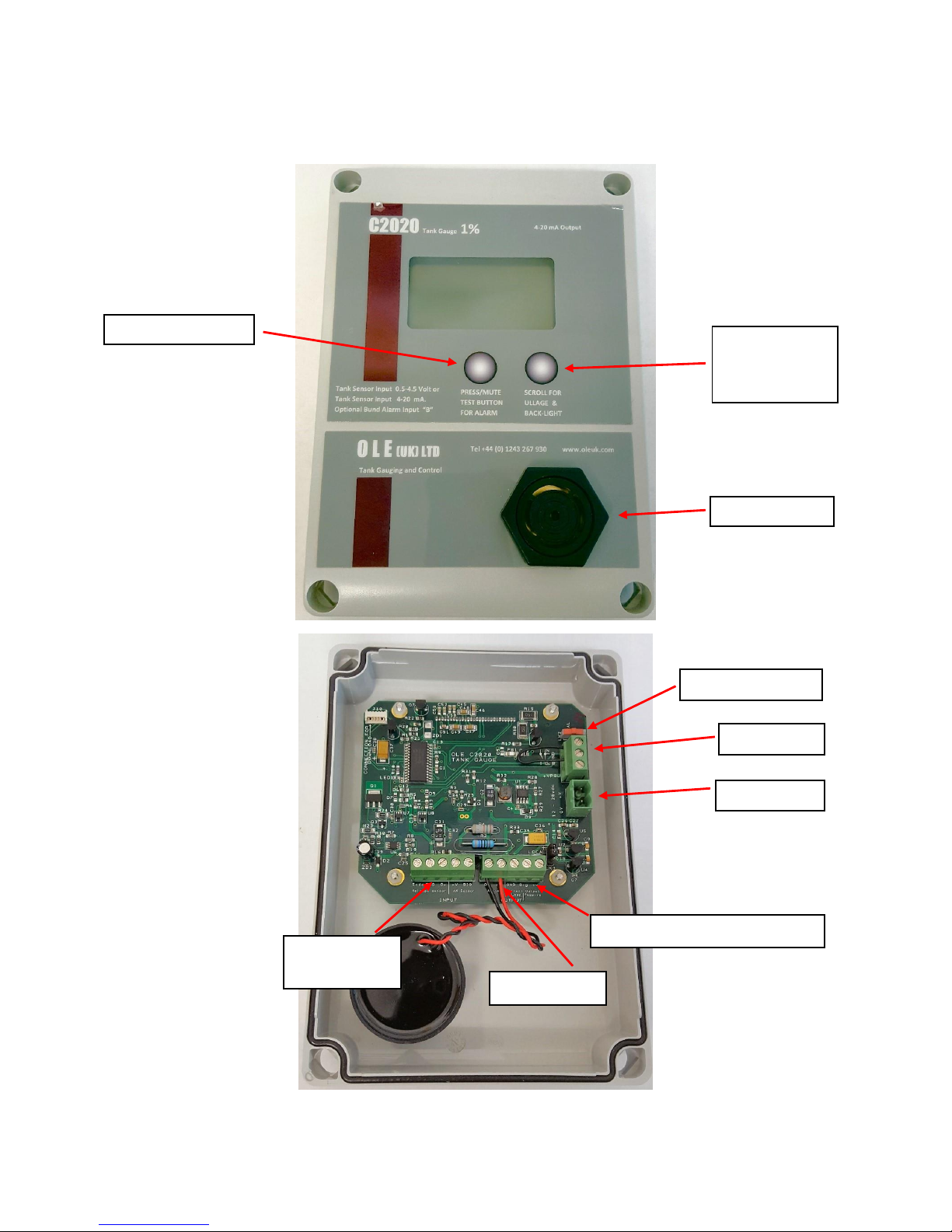
Installation Instructions ........................................................................................................................ 3
Mounting Holes ................................................................................................................................ 3
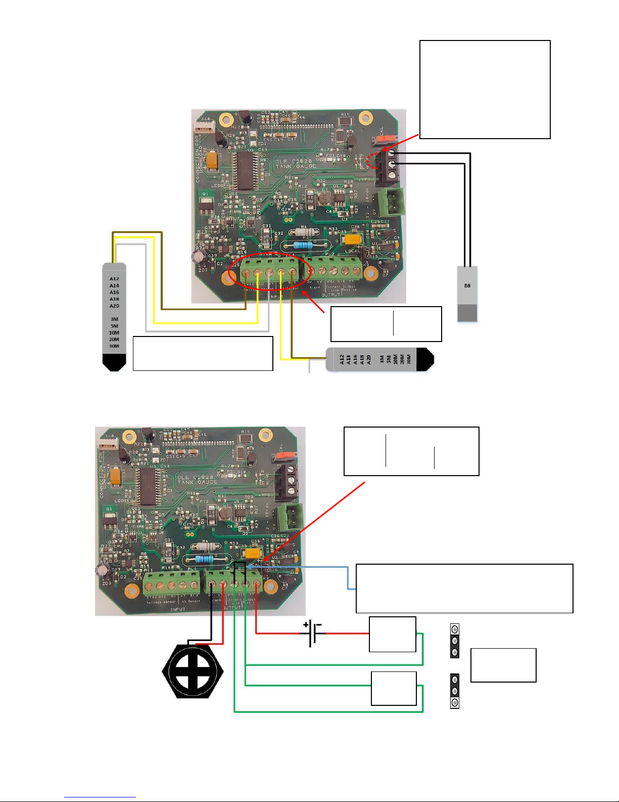
Input Connections............................................................................................................................. 4
Output Connections.......................................................................................................................... 4
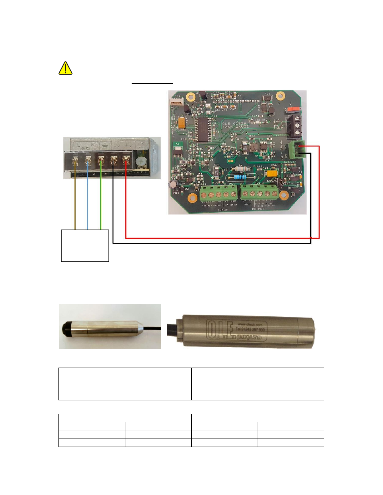
Power Input / Output Connections................................................................................................... 5
Probes............................................................................................................................................... 5
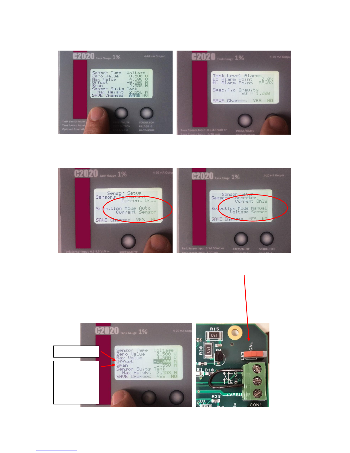
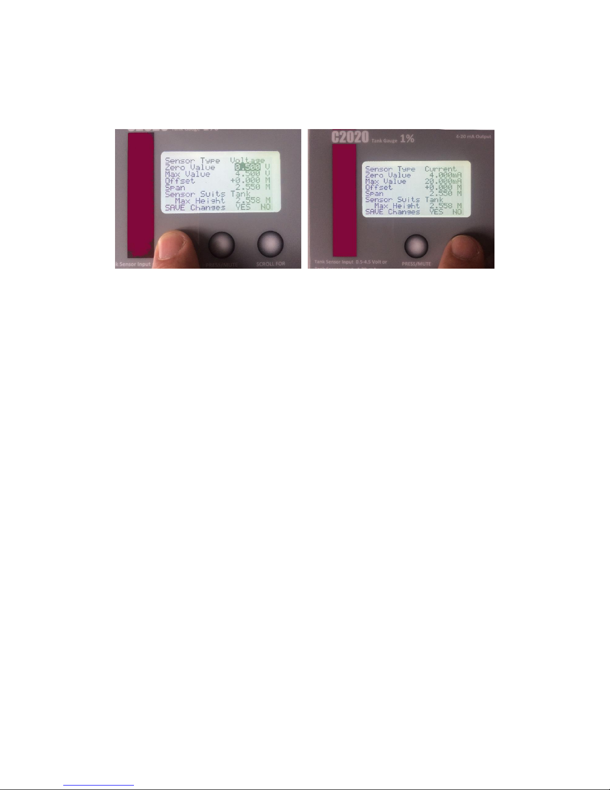
Gauge Configuration......................................................................................................................... 6
High Accuracy Calibration Adjustments............................................................................................ 8
Troubleshooting................................................................................................................................ 8
Operation Instructions.......................................................................................................................... 9
Overview........................................................................................................................................... 9
Appendix 1 (C2020 Wiring Diagram)................................................................................................... 10
Appendix 2 (Accessories) .................................................................................................................... 11
B8 –Bund Probe / Level Switch ...................................................................................................... 11
B2 –Water Sensor .......................................................................................................................... 11

Page 2of 11
Introduction
The Purpose of this document is to outline the installation and operational procedures and
the operation of the C2020.
Safety Warnings
To avoid injury please read this manual carefully before installation. Failure to do so could result in
injury or failure of the equipment, this will invalidate any warranties given.
CAUTION
The installation and assembly of this product may only be performed by a skilled electrician.
WARNING
This product contains 240V AC and 24V DC, Isolate power to the unit before removing the cover.
Contact Information
Principle of Operation
Digital Tank Gauge. Accuracy +/- 1%.
This gauge is fitted in a weatherproof rated IP65 enclosure, for outdoor use. Fitted with a backlight
that enables easy reading. Litres and % Bar are displayed.
OLE (UK) Ltd,
Barns A & B,
Bowely Farm,
Bowely Lane,
South Mundham,
Chichester,
West Sussex,
United Kingdom
PO20 1NB
+44 (0)1243 267930

Page 3of 11
Installation Instructions
Mounting Holes
There are 4 mounting holes in the base of the unit (indicated with the Red Circles).
These are located behind the front panel screws
The distance between mounting holes is 110mm wide X 160mm high.

Page 4of 11
Input Connections
Output Connections
Level Sensors
Voltage or Current
Bund Probe
If No Bund Probe fitted,
replace with wire link.
(Usually Fitted with Unit)
Fit Link where Red Dashed
Line shows
Passive
mA
Loop
mA
Output Analogue 4-20mA
Passive = Externally Powered (Needs Wire Link)
Loop = Powered by C2020 (No Wire Link)
5vdc SIG 0v +V SIG
Voltage Current
0v +V GND SIG +V
Alarm Current Output
Loop Passive
Set Jumper
Accordingly

Page 5of 11
Power Input / Output Connections
WARNING
Before applying the power, DOUBLE CHECK all the connections to the inputs and outputs.
Probes
New Probes Legacy Probes
New Probes
Legacy Probes
C23 = 3.0m Sensor with 10m of cable
C22 = 2.5m Sensor
C25 = 5.0m Sensor with 10m of cable
C27 = 10.0m Sensor with 10m of cable
New Probes –Wire Colours
Legacy Probes –Wire Colours
Brown
+V
Red
+V
Green
Signal
Yellow
Signal
White
0V
Black
0V
100 –240v AC
Maximum
Current - 0.7A

Page 6of 11
Gauge Configuration.
To Calibrate the Gauge, Open the front cover 4 screws, Connect the Tank Probe, and Power the unit.
Toggle the Calibration switch, located top right of the C2020 PCB, marked
Cal (LK2)
1. First screen to show is a “Cube” Tank.
The middle Button scrolls through the
Tank Type Options.
2. Use the “Hidden” Button to scroll
through
the settings.
3. Choose the feature you require, then set the values by using the “Hidden” Button to
select the value to change, then use the other two buttons to Decrease (LEFT) or Increase
(RIGHT) the value.
HIDDEN BUTTON

Page 7of 11
6. Now use the Right Button to scroll across to the Sensor Selection. This should be
Automatic.
If the Automatic does not work, scroll to Mode, and manually select type of sensor with
the Right Button.
7. Sensor Offset.
How far from the bottom of the tank is
the sensor positioned? Enter this here.
As standard we would recommend
50mm which is 0.050m.
Sensor Span. As Standard, this comes
set for 2.55m. Change this to suit the
sensor range you have. Curser Confirm
YES.
8. Toggle the Calibration switch.
The Gauge returns to Standard
Readings.
4. You MUST scroll YES and use the
“Hidden” Button to confirm YES for all
screens
5. Now use the Right Button to scroll
across to Alarm Trigger Points and
Specific Gravity settings.
Sensor Offset
Sensor Span
C22 = 2.55m
C23 = 3.0m
C25 = 5.0m
C27 = 10.0m

Page 8of 11
High Accuracy Calibration Adjustments.
For fine tune Calibration, the sensor settings can be adjusted to suit the individual user.
For Voltage Sensor.
The Maximum Value can be adjusted up or
down to suit. (Both must be adjusted by the
same amount).
If Gauge reads LOW, increase these values.
If Gauge reads HIGH, decrease these values
For Current Sensor.
The Zero Value can be adjusted up or down to
suit.
(Maximum Self Adjusts).
If Gauge reads LOW, increase these values.
If Gauge reads HIGH, decrease these values
Troubleshooting
•Litres Displayed Incorrectly.
Usually down to incorrect settings of the Sensor Span. Check Calibration as shown in
Section 7 –Sensor Span. The Span should match the sensor you have.
C22 = 2.55m (Default), C23 = 3.00m, C25 = 5.00m, C27 = 10.0m
•Display does not read Litres.
Gauges when powered will either read, No Sensor Connected, if there is not one, or one of
the calibration screens may be shown. This can be toggles by switching the Cal switch on the
back of the display board.
If no sensor connected, check that one is connected or check the wiring.

Page 9of 11
Operation Instructions
Overview
Alarm Mute Button
Scroll Button
for Ullage and
Backlight
Audiable Alarm
Alarm Output
4-20mA Output –Loop / Passive
Bund input
Power Input
Sensor Inputs
See Page 4
Calibration Switch

Page 10 of 11
Appendix 1 (C2020 Wiring Diagram)
VIEW FROM BACK
OF CIRCUIT BOARD
MAINS POWER SUPPLY.
Units are supplied with either
24vdc direct connection, or
100/240 Vac power supply.
Power supply connections can
be made by REMOVING the
mounting bracket screws
temporarily.
Power supply Part No T4020-EG
END VIEW POWER
CONNECTIONS
L N E - DC +
For Standard
Voltage Sensor
… wire like this.
C2020-C23/25/27
For mA Sensor
… wire like this.
T4020-Axx and Bxx
Series
3M, 5M and 10M
Bund Alarm is an input for a
mechanical float switch Bund Alarm.
Set NC, (normally closed).
Remove link and wire to these
terminals if Bund Alarm is used
5v Sig 0v +V Sig
Voltage mA
-------- Inputs ---------------------
0 + Gnd Sig V
Alarm Loop / Pass
-------- Outputs --------------
mA
OUTPUT Analog
4-20 milliamp.
Loop = Powered by C2020
(& Multimeter Check)
Siren if fitted
Optional 12-24VDC
Client Supplied
Power Connection

Page 11 of 11
Appendix 2 (Accessories)
B8 –Bund Probe / Level Switch
The Bund Probe has an integral N/C (Normally Closed) level switch.
The Sensor body is made from 304 Stainless Steel and the cap is 316 Stainless Steel. The float is NBR
(Nitrile) which is good in Oil, Diesel, Petrol, most spirits and water based products (SG: 0.7 to 1.5).
The standard cable is Polyurethane sheathed and 6.0m in length and supplied with a 1” fitting.
Supplied as standard: N/C (Float Down –Contact Closed).
Supplied on request, reversed float N/O (Float Down –Contact Open, closed on float rise).
Simple 2 wire connection. See INPUT CONNECTIONS on Page 4 to show where to connect.
B8 - Bund Probe 1” Fitting (Also available as a separate item)
B2 –Water Sensor
The float sinks in less than a Specific Gravity of 0.9 and lifts in water and opens the circuit.
The Sensor body is made from 304 Stainless Steel and the cap is 316 Stainless Steel.
The float is NBR (Nitrile)
Simple 2 wire connection. See INPUT CONNECTIONS on Page 4 to show how where to connect.
B2 –Water Sensor
Other manuals for C2020
1
Table of contents
Other Ole Touch Panel manuals
Popular Touch Panel manuals by other brands

AMX
AMX MT-702 quick start guide

Avalue Technology
Avalue Technology LPC-1507 Quick reference guide

Minebea Intec
Minebea Intec X3 Process Indicator PR 5410 Instrument manual

MITSUBISHI ELECTRIC ENGINEERING
MITSUBISHI ELECTRIC ENGINEERING TSD-AT1521-MN user manual

Loopcomm
Loopcomm S1 user manual

Acnodes
Acnodes PC 2120 Specifications

Christ Elektronik
Christ Elektronik Touch-it CE Pico-ITX operating instructions

Advantech
Advantech PPC-L157T user manual

i3TOUCH
i3TOUCH P5510 user manual

AIS
AIS IPW10ID3S-H1-PoE-PCT user manual

Digital Electronics Corporation
Digital Electronics Corporation PL6900-T42 installation guide

JETWAY
JETWAY HPC170SR-ITQ170 Series user manual