IC nexus EC1400 Instructions for use

EC1400~EC1410
HardwareUserManual
EC1400 NO LCD, with HDMI
EC1403 3.5” LCD with touch screen, NO HDMI
EC1404 4.3” LCD with touch screen, NO HDMI
EC1407 7” LCD and touch screen, NO HDMI
EC1408 8” LCD and touch screen, NO HDMI
EC1410 10.1” LCD and touch screen, NO HDMI
株式会社ロイノス

RELEASENOTES
Version Date NOTES
1.00Nov1st,2011Initialrelease
1.10July,2012RevisedHWboard(B300‐SC)
AddEC1408,EC1410
1.20Dec,2012AddEC1404,EC1403
Disclaimer
This documentation is provided for use with IC Nexus products. No license to IC
Nexus property right is granted. IC Nexus assumes no liability, provides no warranty
either expressed or implied relating to the usage, or intellectual property right
infringement that may result from its use.
IC Nexus provides this document “as is,” without warranty of any kind, either
expressed or implied, including, but not limited to, its particular purpose. IC Nexus
may make changes to this document without notice.
株式会社ロイノス

TableofContent
1.PRODUCT FEATURES AND SPECIFICATIONS..........................................4
1.1 Overview...................................................................................................4
1.2 Features and Specifications.........................................................................9
1.3 Outline Drawing and Dimension.................................................................10
2.FUNCTION DESCRIPTIONS ...................................................................11
2.1 HDMI Connector (EC1400 only).................................................................12
2.2 MicroSD Host Connector...........................................................................13
2.3 UART Connectors & Debug Port.................................................................14
2.4 USB Connectors.......................................................................................18
2.5 Audio Interface........................................................................................19
2.6 Ethernet Interface....................................................................................20
2.7 LED.........................................................................................................21
2.8 Power Supply (DC-IN connector) ...............................................................22
2.9 BM Header ..............................................................................................23
2.10 GPIO Connector (EC1407/08/10 only)......................................................24
2.11 I2C Interface..........................................................................................25
APPENDIX A:BOX HEADER TO DB9 CABLE............................................26
APPENDIX B:7-INCH LCD BRIEF.............................................................27
APPENDIX C:8-INCH LCD BRIEF.............................................................29
APPENDIX D:10.1-INCH LCD BRIEF.........................................................31
APPENDIX E:3.5-INCH LCD BRIEF ..........................................................33
APPENDIX F:4.3-INCH LCD BRIEF ..........................................................35
株式会社ロイノス

1.Product Features and Specifications
1.1Overview
EC1400 is a series of ARM11-based embedded computer products with a rich set of
features. It is a flexible, high performance and inexpensive computer designed for
multimedia applications especially in 1080p video decoding.
Each EC1400 device can be pre-installed with Windows CE 6.0, Linux 2.6 OS or Android
2.3 for immediate evaluation.
The EC1400 series of products include the following models:
EC1400: no LCD, with HDMI output
EC1403: with 3.5-inch (320x240) LCD and touch screen, NO HDMI
EC1404: with 4.3-inch (480x272) LCD and touch screen, NO HDMI
EC1407: with 7-inch (800x480) LCD and touch screen, NO HDMI
EC1408: with 8-inch (800x600) LCD and touch screen, NO HDMI
EC1410: with 10.1-inch (1024x600) LCD and touch screen, NO HDMI
株式会社ロイノス

EC1407 front panel (HDMI is only for EC1400):
(EC1407 with Linux)
Figure 1- 1 EC1407 front panel photo
NOTE: EC1400 dimension is the same as EC1407, except that EC1400 has no front
panel.
114 mm
200 mm
29mm
株式会社ロイノス

EC1408 front panel:
(EC1408 with WinCE)
Figure 1- 2 EC1408 front panel photo
165 mm
212 mm
47mm
32mm
177 mm
株式会社ロイノス

EC1410 front panel:
(EC1410 with Android)
Figure 1- 3 EC1410 front panel photo
170 mm
263 mm
47mm
32mm
177 mm
株式会社ロイノス

EC1403/EC1404 Photo:
Figure 1- 4 EC1403/EC1404 photos
79 mm
118 mm
37 mm
79 mm 79 mm
93 mm
12 mm
株式会社ロイノス

1.2FeaturesandSpecifications
Features:
ARM1176JZF processor at high performance (>600Mhz) and low power
consumption
Dedicated hardware MPEG2/4/H.264 1920x1080 Full HD decoder
Dedicated hardware H.264 1280x720 HD encoder
Hardware 2D/3D graphic accelerator
Pre-installed Windows CE 6.0, Linux 2.6 or Android 2.3 OS
Rich set of peripherals (LCD, USB, HDMI, …etc)
EC1400 Specifications:
ARM1176JZF @ 700Mhz, 16KB/16KB cache, 16KB/16KB TCM
256MB DDR2 SDRAM (32-bit)
512MB NAND Flash (8-bit)
Hardware Video Decoder:
H.264 HP @ Level 5.0 ( up to 25Mbps)
MPEG 1/2 MP@HL (up to 40Mbps)
Hardware Video Encoder:
MPEG 4 : up to 1280x720p (30fps)
H.264 : up to 1280x720p (24fps)
10/100 Mb Ethernet interface RJ-45 connector x1
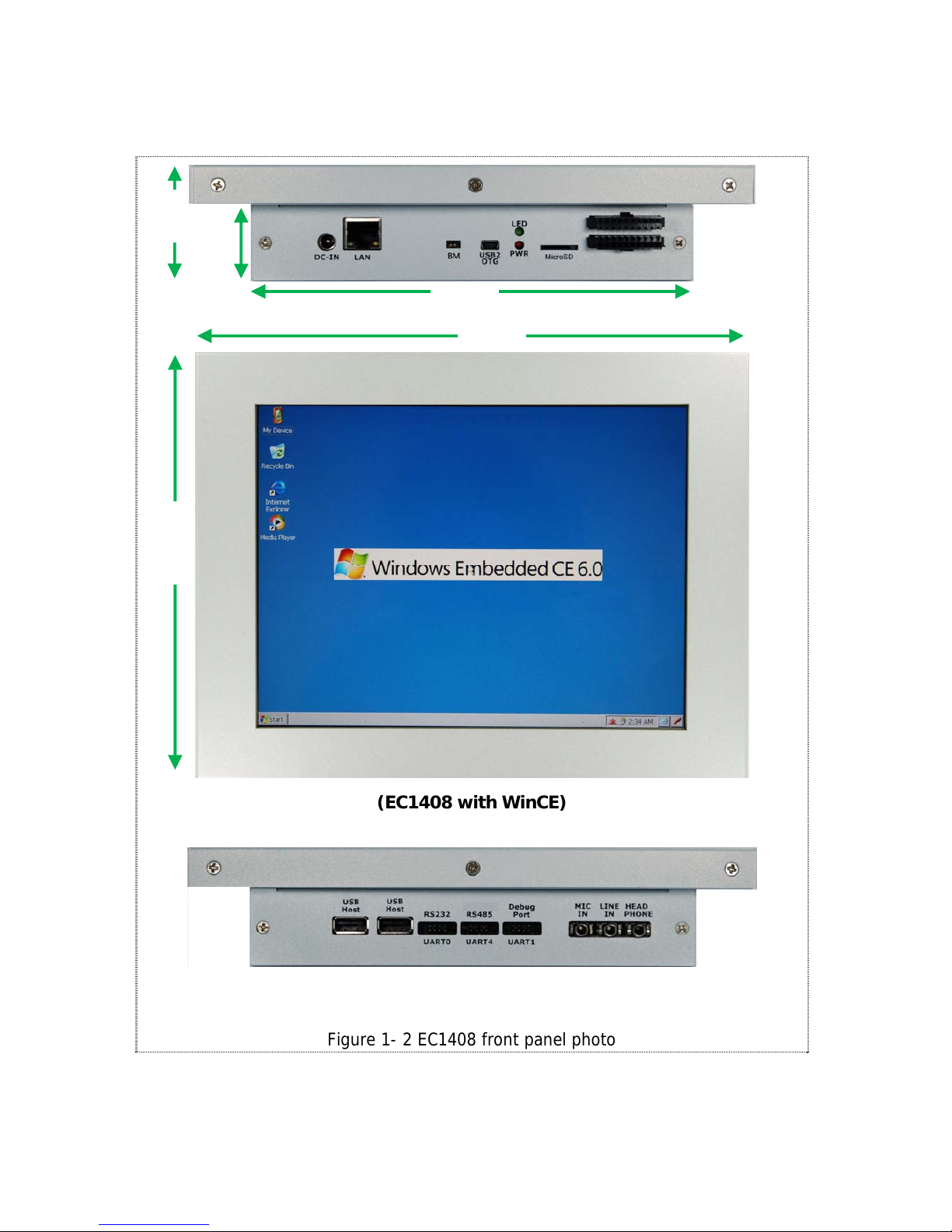
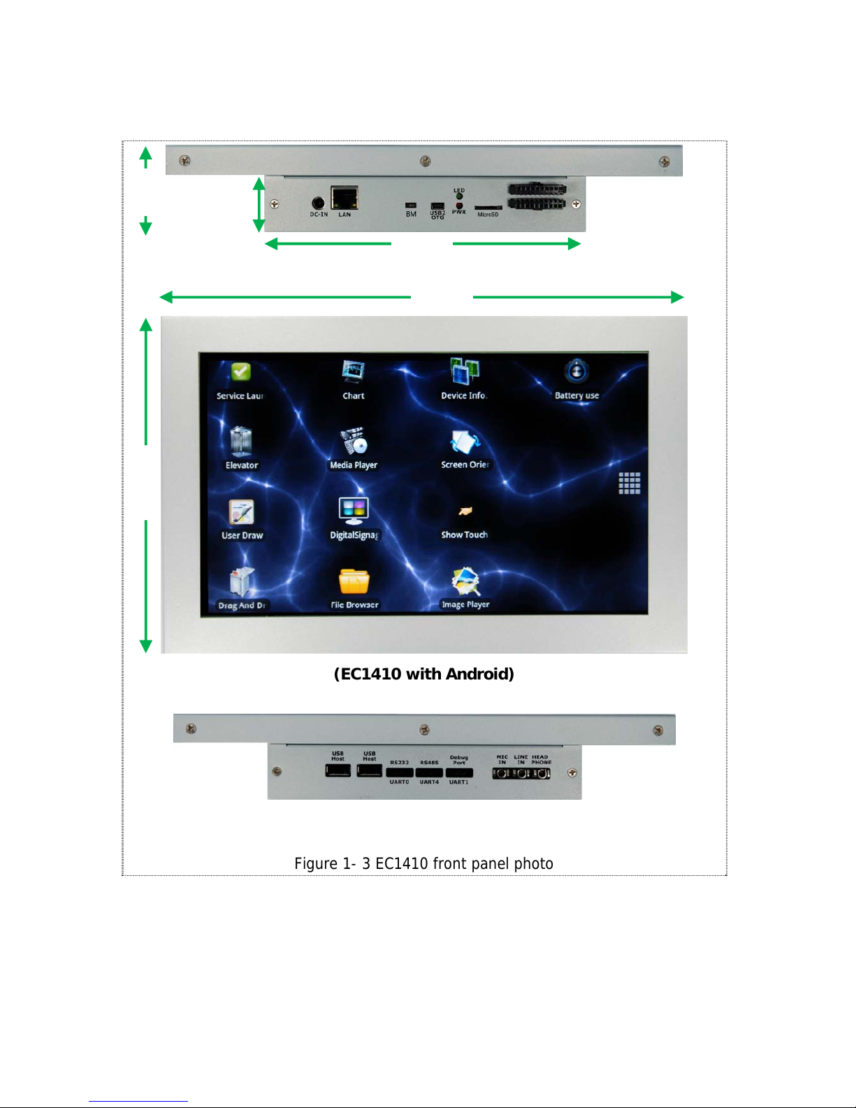
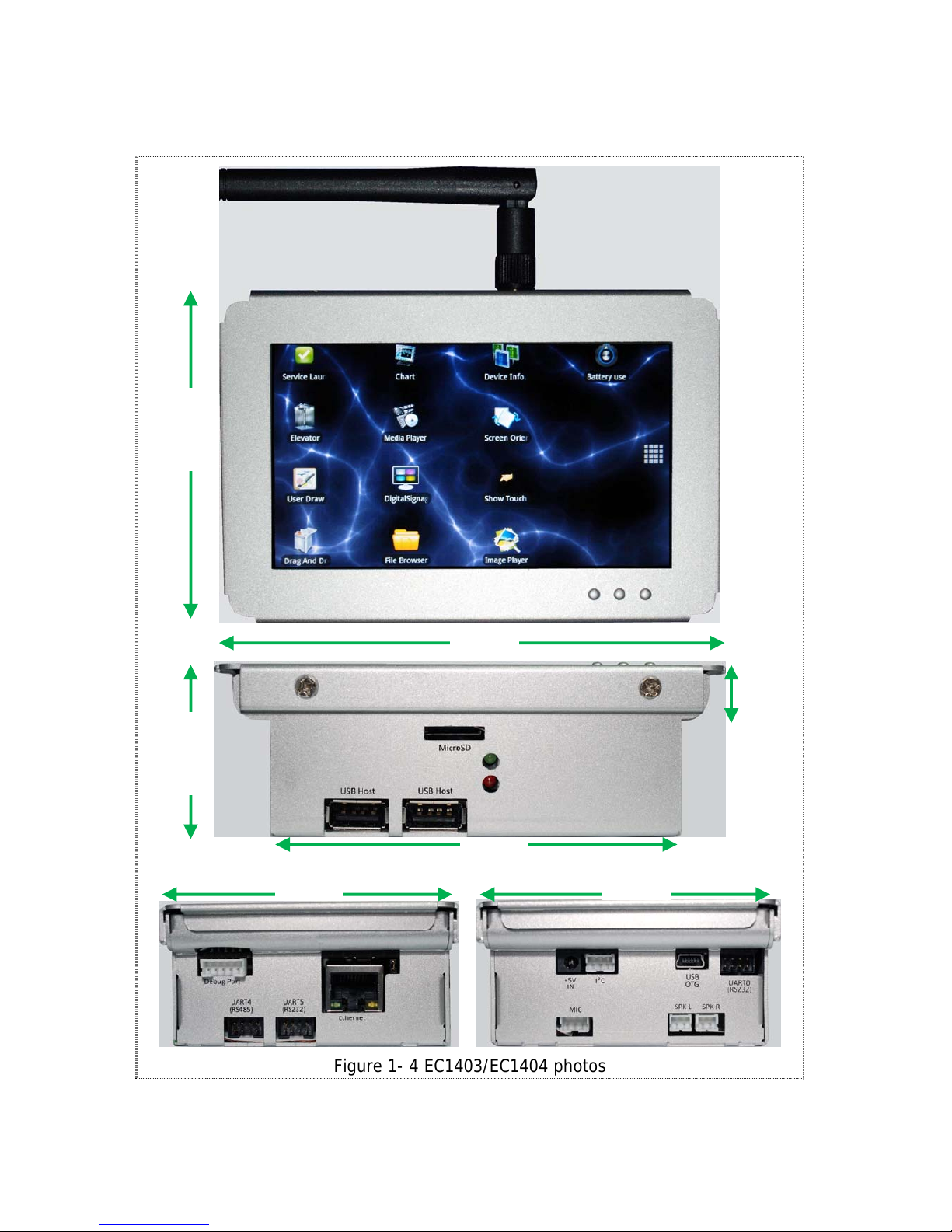
3.5”, 4.3”, 7”, 8” or 10.1” LCD panel with touch screen x1
HDMI 1.3 transmitter connector x1 (EC1400 only)
+12V DC power input connector x1 (EC1407/08/10 only)
+5V DC power input connector x1 (EC1403/04 only)
USB1.1 host connector x2
USB2.0 OTG connector x1
Micro SD card socket x1
WM8731 Audio Codec , Amplifier circuit
Line-in connector x1, Earphone connector x1 (EC1407/08/10 only)
MIC-in connector x1
Speaker connector x2 (EC1403/04 only)
RS485 connector x1
RS232 connector x2 (one for debug port) (EC1407, EC1408, EC1410)
RS232 connector x3 (one for debug port) (EC1403, EC1404)
株式会社ロイノス

1.3OutlineDrawingandDimension
<< TBD >>
株式会社ロイノス

2.Function Descriptions
The following diagrams show connector positions on EC1400 series of products. The
functional details of the connectors are described in subsequent sections.
Connector Positions for EC1403 and EC1404:
Connector Positions for EC1407, EC1408 and EC1410:
I
2
C+5V
IN USB
OTG UART0
(RS232)
SPK L SPK RMIC
MicroSD
USB
Host USB
Host
Ethernet
Debu
g
UART4
(RS485) UART5
(RS232)
BM
USB
Host Debu
g
Port
RS485
(UART4) LINE
IN
RS232
(UART0) Head
Phone
MIC
IN
USB
Host I
2
C
LAN
DC-IN BM PWR
LED
Mi
c
r
o
S
D
USB2
OTG
G
PI
O
株式会社ロイノス

2.1HDMIConnector(EC1400only)
The HDMI receptacle connector supports standard HDMI interface.
The brief features of the HDMI interface are:
HDMI 1.3, HDCP 1.1, DVI 1.0 compliant
Supported video format:
480p @59.94Hz/60Hz, 576p@50Hz
720p @50Hz/59.94Hz/60Hz
1080i @50Hz/59.94Hz/60Hz
1080p @50Hz/59.94Hz/60Hz
Supported color format: 4:4:4 RGB/YCbCr, 4:2:2 YCbCr 12-bit mode
Integrated HDCP Encryption Engine for Video/Audio content protection
株式会社ロイノス

2.2MicroSDHostConnector
The microSD host connector complies with the following versions of specifications:
SD Host Controller Specification Version 2.0
SDIO Card Specification Version 2.0
SD Memory Card Specification Draft Version 2.0
SD Memory Card Security Specification Version 1.0
The microSD interface supports 4-bit data bus.
株式会社ロイノス

2.3UARTConnectors&DebugPort
There are 3 UART ports (UART0, 4, 5) on EC1403/04 and 2 UART ports (UART0, UART4)
on EC1407/08/10. The connector type and functions are described in the table below:
UART
No Connector
Type Available
Signals Note
UART0 2x4 box
header RS232 signal level
(TX, RX, RTS, CTS) RS232 port.
UART4 2x4 box
header RS485 signal level
(485+, 485-) RS485 port.
Note: RS485 port works only
in HALF Duplex mode.
UART5 2x4 box
header RS232 signal level
(TX, RX, RTS, CTS) RS232 port.
Note: EC1403/EC1404 only.
One 2x4 box header to DB9 cable is included in the product package. See Appendix A
for the detailed info of cable pin assignment.
2x4 Box Header:
DB9
Pin 2x4
header RS232 RS485
1 -- --- ---
2 4 RxD 485+
36
T
xD 485-
4 1 --- ---
5 5 GND GND
6 7 --- ---
7 8 RTS ---
8 2 CTS ---
9 -- --- ---
DB9 Male Connector
DB9 Female Connector
1
2
1 2 3 4 5
6 7 8 9
54 321
987 6
7
8
株式会社ロイノス

UART1 (only TX, RX signals) is dedicated as a debug port.
The default setting of UART1 is: 115200 baud rate, 8 data bit, no parity, 1 stop
bit and no flow control.
A DB9 null modem cable (or adapter) is required when you would like to connect
UART1 to a PC that runs terminal emulation software such as TeraTerm.
UART0 (with TX, RX, RTS, CTS signals) works as a regular RS232 port.
ARM11
CPU RS232
Transceiver 2x4
Box Header
T
X, R
X
RTS
,
CTS
UART0 connection dia
g
ram:
UART1 connection dia
g
ram:
EC14xx
UART1
株式会社ロイノス

UART Box Header (CN16 on PCB) Pin assignment:
If you are using an RS232 cable in RS485 connection, please make sure the pin2 and
pin 3 are cross connected. See the sample cable wiring diagram below:
UART4 connection dia
g
ram:
ZT485E: RS485 transceiver. RS485 works in half duplex mode.
ARM11
CPU 2x4
Box Header
ZT485E
EC14xx
(UART4
RS485)
1
2
357
468
4
6
: 485+
: 485-
株式会社ロイノス

Debug Port Connector:
The debug port on EC1400 device is a RS232 port for software development or for
Linux console port. Note that EC1403 and EC1404 debug port require a dedicated
debug cable which is included in the EC1403/EC1404 product package. See table
below:
Device UART
No Connector
Type Available
Signals Note
EC1407
EC1408
EC1410 UART1 2x4 box
header RS232
(TX, RX) Use the cable as in Appendix A.
EC1403
EC1404
UART1 1x5 box
header RS232
(TX, RX) Use a dedicated debug cable
for this port.
株式会社ロイノス

2.4USBConnectors
The USB interfaces on EC1400 include a USB 2.0 OTG port (support 480Mbps speed)
and 2x USB1.1 host ports.
The USB1.1 host interface is connected to a hub controller to extend host ports.
2 of the USB1.1 hub ports are available for users.
NOTE: The USB2.0 OTG can be used in host mode or device mode. If you would like to
use it in host mode, a separate OTG-to-host cable is required.
The USB1.1 host connector is a regular USB type A connector that can be connected to
+5V USB storage device. This port is mainly used to connect to USB flash drive.
USB Port:
ARM11
CPU
4-port
Hub USB1.1
Host Connectors
USB2 OTG
USB1.1 Host
USB2.0 OTG
Connecto
r
株式会社ロイノス

2.5AudioInterface
The EC1400 audio interface is implemented by a WM8731 audio codec. The data and
control interface between CPU and WM8731 is I2S.
On EC1407/EC1408/EC1410, the available audio connectors are head phone, line in
and MIC. The speaker connectors (left, right) are not available for external connection.
On EC1403/EC1404, the available audio connectors are MIC, speaker Left and speaker
Right.
A
udio Interfaces:
ARM11
CPU
WM8731
Audio
Codec
Amplifier
Head Phone (out)
I2S
Line In (in)
MIC (in)
Speaker
株式会社ロイノス

2.6EthernetInterface
The 10/100Mbps Ethernet interface is available at the standard RJ-45 connector.
ARM11
CPU
Ethernet:
RJ-45
Connector
Ethernet
Controller
株式会社ロイノス
This manual suits for next models
5
Table of contents