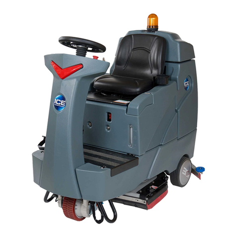
Ice iS1100 Programming manual

Operator & Parts Manual
Ride-on Auto Sweeper
www.icecompanies.com
7000702U
REV.02(08-2016)
iS1100
INTERNATIONAL CLEANING EQUIPMENT
https://harrissupplyind.com-ToOrderPartsCall608-268-8080

HOW TO ORDER PARTS
Only use ICE Company supplied or equivalent parts. Parts and supplies may be ordered
online,by phone, by fax or by mail.
1. Identify the machine model.
2. Identify the machine serial number from the data label.
3. Ensure the proper serial number is used from the parts list.
4. Identify the part number and quantity.
Do not order by page or reference numbers.
5. Provide your name, company name, customer ID number,billing and shipping address,
phone number and purchase order number.
Please ll out at time of installation for future reference.
Model No.
Serial No.
Machine Options
Sales Rep.
Sales Rep. phone no.
Customer ID Number
Installation Date
READ OPERATOR MANUAL MANUAL CAREFULLY
International Cleaning Equipment
XiangShi Road, LiaoBu, DongGuan, GuangDong, China
Tel:0769-8186 9000
Fax:0769-8186 300
www.icecompanies.com
Specifications and parts are subject to change without notice.
PROTECT THE ENVIRONMENT
Please dispose of packaging materials,old machine components
such as batteries, hazardous fluids, including antifreeze and oil,
in an environmentally safe way according to local waste disposal
regulations.
Always remember to recycle.
IMPORTANT:To ensure full warranty protection,Please ll out
& return your warranty card.
https://harrissupplyind.com-ToOrderPartsCall608-268-8080

ICE iS1100 1
TABLE OF CONTENTS
SAFETY PRECAUTIONS............................................................................................................... 2-3
MACHINE COMPONENTS ...................................................................................................................... 4-8
SPECIFICATIONS ......................................................................................................................................... 9
WIRING DIAGRAM ................................................................................................................................. 10-11
OPERATION .................................................................................................................................................. 12
BATTERY CHECK ON A NEW MACHINE ....................................................................................................... 12
SWEEPING AND BRUSH INFORMATION ...................................................................................................... 13
STARTING AND STOPPING THE MACHINE ...................................................................................................14
MACHINE OPERATION ....................................................................................................................................15
HOPPER EMPTYING ........................................................................................................................................15
AFTER USING THE MACHINE .........................................................................................................................15
PUSHING/TOWING THE MACHINE .................................................................................................................15
MACHINE STORAGE .......................................................................................................................................15
FIRST PERIOD OF USE ...................................................................................................................................15
MAINTENANCE ............................................................................................................................................ 16
SCHEDULED MAINTENANCE TABLE .............................................................................................................16
MAIN BRUSH HEIGHT CHECK AND ADJUSTMENT........................................................................................17
MAIN BRUSH REPLACEMENT ........................................................................................................................18
SIDE BRUSH HEIGHT CHECK AND ADJUSTMENT .......................................................................................19
SIDE BRUSH REPLACEMENT..........................................................................................................................19
DUST FILTER CLEANING AND INTEGRITY CHECK ......................................................................................20
SKIRT HEIGHT AND OPERATION CHECK ..................................................................................................... 21
BATTERY CHARGING ......................................................................................................................................22
FUSE CHECK/REPLACEMENT.........................................................................................................................23
ALARMS&TROUBLESHOOTING ...........................................................................................................24
SCRAPPING ...................................................................................................................................................... 24
PARTS LIST...... ............................................................................................................................................. 25
CHASS ASSEMBLY............................. .........................................................................................................25-26
BODY ASSEMBLY.........................................................................................................................................27-29
MAIN BRUSH ASSEMBLY ...........................................................................................................................30-32
RIGHT SIDE BROOM ASSEMBLY ..............................................................................................................33-34
LEFT SIDE BRUSH ASSEMBLY...................................................................................................................35-36
STEERING ASSEMBLY ...............................................................................................................................37-41
FRONT WHEEL ASSEMBLY ...................................................................................................................... 42-43
PEDAL ASSEMBLY ......................................................................................................................................44-45
DRIVE ASSEMBLY........................................................................................................................................46-47
SKIRTS ASSEMBLY............................. .........................................................................................................48-49
DUST CONTROL ASSEMBLY.......................................................................................................................50-51
HOPPER ASSEMBLY ...................................................................................................................................52-53
ELECTRONIC BOX ASSEMBLY ..................................................................................................................54-55
BATTERY GROUP&BATTERY GROUP........................................................................................................56-57
ACCESSORIES........... .................................................................................................................................58-59
WEAR&TEAR PARTS ..................................................................................................................................... 60
https://harrissupplyind.com-ToOrderPartsCall608-268-8080

2 ICE iS1100
OPERATOR
SAFETY PRECAUTIONS
The following symbols indicate potentially dangerous situations. Always read this information
carefully and take all necessary precautions to safeguard people and property.
The operator’s cooperation is essential in order to prevent injury. No accident prevention
program is effective without the total cooperation of the person responsible for the machine
operation. Most of the accidents that may occur in a factory, while working or moving around,
are caused by failure to comply with the simplest rules for exercising prudence. A careful
and prudent operator is the best guarantee against accidents and is essential for successful
completion of any prevention program.
SYMBOLS
DANGER!
It indicates a dangerous situation with risk of death for the operator.
WARNING!
It indicates a potential risk of injury for people or damage to objects.
CAUTION!
It indicates a caution or a remark related to important or useful functions. Pay careful attention to
the paragraphs marked by this symbol.
NOTE :
It indicates a remark related to important or useful functions.
GENERAL INSTRUCTIONS
Specic warnings and cautions to inform about potential damages to people and machine are
shown below.
DANGER!
- Before performing any maintenance, repair, cleaning or replacement procedure
disconnect the battery connector, remove the ignition key and engage the parking
brake.
- This machine must be used by properly trained operators only. Children or disabled
people cannot use this machine.
- Sharp turns must be made at slowest possible speed.Avoid abrupt turns on incline.
- Keep the batteries away from sparks, ames and incandescent material. During the
normal operation explosive gases are released.
- Do not wear jewels when working near electrical components.
- Do not work under the lifted machine without supporting it with safety stands.
- When working under the open hood, ensure that it cannot be closed by accident.
- Do not operate the machine near toxic, dangerous, ammable and/or explosive
powders, liquids or vapors. This machine is not suitable for collecting dangerous
powders.
- If the machine is equipped with lead (WET) batteries, battery charging produces highly
explosive hydrogen gas. Keep the hood open when charging the batteries and perform
this procedure in well-ventilated areas and away from naked ames.
- When lead batteries (WET) are installed on this machine, do not tilt the machine more
than 30° from its horizontal position to not allow the highly corrosive acid to leak out of
the batteries. When the machine is to be tilted to perform maintenance procedures,
remove the batteries.
https://harrissupplyind.com-ToOrderPartsCall608-268-8080

ICE iS1100 3
OPERATOR
WARNING!
- Carefully read all the instructions before performing any maintenance/repair procedure.
-Take all necessary precautions to prevent hair, jewels and loose clothes from being caught by the
machine moving parts.
- When the machine is equipped with lead batteries (WET), don’t smoke while charging the batteries.
- Before using the battery charger, ensure that frequency and voltage values, shown on the machine
serial number plate, match the electrical mains voltage.
- Do not pull or carry the machine by the battery charger cable and never use the battery charger
cable as a handle. Do not close a door on the battery charger cable, or pull the battery charger cable
around sharp edges or corners. Do not run the machine on the battery charger cable. Keep the
battery charger cable away from heated surfaces.
- Do not charge the batteries if the battery charger cable or the plug are damaged. If the battery
charger cable is damaged, contact ICE Service Center.
- To reduce the risk of re, electric shock, or injury, do not leave the machine unattended when it is
plugged in. Before performing any maintenance procedure, disconnect the battery charger cable from
the electrical mains.
- To avoid any unauthorized use of the machine, remove the Ignition key.
- Do not leave the machine unattended without being sure that it cannot move independently.
- Do not use the machine on slopes with a gradient exceeding the specications.
- Use only brushess supplied with the machine and those specied in the Opeartion Manual. Using
other brushes could reduce safety.
- Before using the machine, close all doors and/or covers.
- Do not use the machine in excessively dusty areas.
- Do not wash the machine with direct or pressurised water jets, or with corrosive substances.
- Do not use compressed air to clean this type of machine, except for the lters (see the relevant
paragraph).
- While using this machine, take care not to cause damage to other people, and children especially.
- Do not put any can containing uids on the machine.
- The machine storage temperature must be 32°F to 104°F (0°C to +40°C).
- The machine working temperature must be 32°F to 104°F (0°C to +40°C).
- The humidity must be between 30% and 95%.
- Always protect the machine against the sun, rain and bad weather, both under operation and inactivity
condition. Store the machine indoors, in a dry place. This machine must be used in dry conditions, it
must not be used or kept outdoors in wet conditions.
- Do not use the machine as a means of transport, or for pushing/towing.
- Do not allow the brushes to operate while the machine is stationary to avoid damaging the oor.
- In case of re, possibly use a powder re extinguisher, not a water one.
- Do not bump into shelves or scaffoldings, especially where there is a risk of falling objects.
- Adjust the operation speed to suit the oor conditions.
- This machine cannot be used on roads or public streets.
- Do not tamper with the machine safety guards.
- Follow the routine maintenance procedures scrupulously.
- Do not remove or modify the plates afxed to the machine.
- In case of machine malfunctions, ensure that these are not due to lack of maintenance. Otherwise,
request assistance from the authorised personnel or from an authorised Service Center.
- If parts must be replaced, require ORIGINAL spare parts from an Authorised Dealer or Retailer.
- To ensure machine proper and safe operation, the scheduled maintenance shown in the relevant
chapter of this Manual must be performed by the authorised personnel or by an authorised Service
Center.
- The machine must be disposed of properly, because of the presence of toxic-harmful materials
(batteries, oils, etc.), which are subject to standards that require disposal in special centres (see the
Scrapping chapter).
https://harrissupplyind.com-ToOrderPartsCall608-268-8080

4ICE iS1100
OPERATOR
MACHINE COMPONENTS
1. Steering wheel
2. Speed control pedal
3. Front skirt lifting pedal
4. Can holder
5. Body
6. Rear driving wheels on xed axle
7. Front steering wheel
8. Right side brush
9. Left side brush
10. Main brush
11. Left side skirt
12. Right side skirt
13. Front skirt
14. Rear skirt
15. Emergency push-button
Press it in case of emergency to stop
all the machine functions. To deactivate
the emergency push-button, turn it in the
direction shown by the arrow.
16.Left cover (to be opened for performing
maintenance procedures only)
17. Cover nuts
18. Flashing light (always on when the ignition
key is turned to “I”)
19. Driver’s seat with safety microswitch
20. Seat longitudinal position adjusting lever
21. Led light
22. Working light (optional)
23. Right side brush height adjusting knob
24. Left side brush height adjusting knob
25. Machine lifting anchors
26. Front bumper
27. Body opening handles
27a.Off-board battery charger port
1
2
3
4
4
5
6
7
89
12
10
1113
14
17
16
18
18
19
21
22 20
23
24
26 25
27
27
15
4
27a
https://harrissupplyind.com-ToOrderPartsCall608-268-8080

ICE iS1100 5
OPERATOR
MACHINE COMPONENTS (Continues)
28. Hopper (empty it when it is full)
29. Hopper fastening hook
30. Hopper handle
31. Exhaust hole
32. Hopper wheel
33. Right cover (for main broom removal)
34. Door knobs
35. Tool Holder
36. Vacuum llter compartment cover
37. Cover knobs
38. Internal containers with handle for dumping
39. Serial decal
28 29
30
31
32
34
33
35
36
37
4
39
25
38
38
https://harrissupplyind.com-ToOrderPartsCall608-268-8080

6 ICE iS1100
OPERATOR
MACHINE COMPONENTS (Continues)
46. Electrical component box
47. Electrical component cover
48. Machine connector
49. Main broom height adjusting knob
50. Vacuum Fan cover
51. Vacuum fan
40. Body rope
41.Lead batteries (WET) or AGM batteries
42. Battery connection diagram
43. Battery caps (for WET batteries only)
44. Battery connector
45. Battery container
40
44
41
43
42
41
50
51
49
47
45
46
48
41
https://harrissupplyind.com-ToOrderPartsCall608-268-8080

ICE iS1100 7
OPERATOR
MACHINE COMPONENTS (Continues)
Electrical component box
56. Lamellar fuse box
57. Electronic battery charger
58. Charged battery warning light
59. Electrical component box
59a. Lamellar fuse box cover
52. Drive system electronic board
53. Drive system malfunction led. If the led
is on, the drive system is operating, if the led
ashes, the drive system is malfunctioning
54. Pillar
55. Main fuse
52
53
57 58
54 55 56 59
59a
https://harrissupplyind.com-ToOrderPartsCall608-268-8080

8iCE IS1100
OPERATOR
MACHINE COMPONENTS (Continues)
CONTROL PANEL
60. Cover, Steering wheel
61. Steering wheel
62. LCD display screen.
63. Speed increasing switch
64. Speed deincreasing switch
65.Backward direction switch,Buzzer indicates
if backward direction is active(buzzer on) or
not(buzzer off)
66. Buzzer enable switch
67. Vacuum enable switch
68. Filter shaker switch
69. Left and right side brush lifting/lowering lever
70. Switch (working light)
71. Ignition key (when turned to “0” it turns the
machine off and disables all functions; when
turned to “I” it enables all machine functions; it
also turns on the ashing light)
72. Main broom lifting/lowering lever
73. Panel fastening screws
ACCESSORIES/OPTIONS
In addition to the standard components, the machine can be equipped with the following accessories/options,
according to the machine specic use:
– Main and side brooms with harder or softer bristles
– Working light
– Skirts of various materials
– Protective roof
For further information concerning the optional accessories, contact an authorised Retailer.
62
63
64
66
68
67
61 65
69 70 71
72
60
73
At power on, the display shows: battery voltage, hourmeter and software release
(for about 1 second). Then system instantaneous conditions are shown: active
functions, battery charge, active alarms…
BATTERY LEVEL INDICATOR
The battery level indicator shows the charge
level of the batteries with a segmented display.
When the batteries are fully charged,all the
segments are lit ,As the batteries discharge,the
segments shut off.
The batteries should be recharged when only
one degment displays.At this point, the battery
icon will begin flashing,and sweeping and
vacuum will automatically shut off to alert the
operator of the battery condition.
when all the degments have shut off,everything
set off.
https://harrissupplyind.com-ToOrderPartsCall608-268-8080

ICE IS1100 9
OPERATOR
SPECIFICATIONS
General Values
Machine length 59 in (1,500 mm)
Machine width (without side brushes) 36.8 in (937 mm)
Machine maximum height (at the steering wheel) 50.3 in (1,250 mm)
Cleaning width (without side brushes) 27.6 in (700 mm)
Cleaning width (with side brushes) 50.8 in (1,290 mm)
Minimum distance from the oor (skirts not included) 2.6 in (67 mm)
Main brush size (diameter x length) 11.8 x 27.6 in (300 mm x 700 mm)
Side brush diameter 17.7 in (450 mm)
Main brush speed 550 rpm
Side brush speed 80 rpm
Front steering wheel diameter 11.8 in (300 mm)
Rear driving wheel diameter 11.8 in (300 mm)
Front wheel specic pressure on the oor 159.5 psi (1.1 N/mm2)
Rear wheel specic pressure on the oor 101.5 psi (0.7 N/mm2)
Total machine weight (without batteries) 573.2 lb (255 kg)
Hopper capacity 21.2 gal (80 liters)
Main brush motor 0.67 HP (500 W)
Side brush motors 0.1 HP (80 W)
Drive system motor 0.8 HP (600 W), 110 rpm
Vacuum system motor 0.41 HP (310 W)
Filter shaker motor 0.13 HP (100 W), 6,500 rpm
Sound pressure level at workstation (A Lpa) 63.8 dB(A)
Vibration level at the operator’s arms (*) <8.2ft/s2(2.5m/s2)
Vibration level at the operator’s body (*) <1.9ft/s2(0.6m/s2)
(*) Under normal working conditions, on a level asphalt surface.
Performance Values
Maximum forward/reverse speed 3.7 mph (6 km/h)
Maximum reverse speed 1.8 mph (3 km/h)
Gradeability 11.3° (20 %)
Minimum turning radius 51.6 in(1,310mm)
Batteries Values
Battery voltage 24 V
Battery capacity 260 Ah C20 (WET)
Battery capacity 220 Ah C20 (AGM)
Battery container inner size (length x width xheight) 21x14.7x6.1in(534x374x155mm)
Dust vacuuming and ltering Values
Paper dust lter 5-10 μm 38.8ft2(3.6m2)
Main brush compartment vacuum 0.43 in (11mm H2O)
Filter shaker activation Electric
https://harrissupplyind.com-ToOrderPartsCall608-268-8080

10 ICE iS1100
OPERATOR
WIRING DIAGRAM
+-
YE 27
GN 6
BK 0
+-
+
+--
18AWG WH 18
18AWG BU 26 18AWG RD 7
18AWG BU 0
18AWG BK 24
18AWG RD 22
18AWG YE 23
16AWG WH 8
+-
18AWG BK 0
16AWG RD 7
18AWG BK 16
18AWG RD 5
RD 33
GN 6
WH 27
18AWG GY 19
18AWG BK 0
18AWG BK 0
18AWG BK 018AWG GN 17
BN 33
BU 0
12AWG RD
12AWG BK
16AWG BK 21
18AWG WH 20
18AWG BK 0
18AWG BK 25
16AWG RD 7
18AWG RD 7
18AWG RD 7
18AWG RD 7
18AWG RD 7
18AWG BK 0
18AWG RD 29 18AWG RD 28
18AWG BU 0
18AWG BN 29
18AWG BK 0
18AWG RD 29
18AWG BK 0
18AWG RD 29
18AWG RD 28
16AWG BK 0
16AWG BK 0
PU 4*0.5mm2
YGCP 4*0.5mm2
18AWG RD 1 18AWG RD 1 18AWG RD 2
6AWG RD
+
+
6AWG RD
6AWG BK 6AWG BK
6AWG BK
14AWG
9
GY
14AWG
8
WH
10AWG
13
BU
10AWG
12
BN
8AWG
BK
8AWG
RD
10AWG
15
BK
10AWG
14
RD
14AWG
11
BK
14AWG
10
VT
14AWG
10
VT
14AWG
11
BK
12AWG
GN
18AWG
2
RD
18AWG
4
BN
18AWG
4
BN
18AWG
29
RD
-
-
https://harrissupplyind.com-ToOrderPartsCall608-268-8080

ICE iS1100 11
OPERATOR
BAT Batteries, 24V
CH1 Battery charger
DB Display board
EB1 Function controller board
Fuse1 Main fuse (150A)
Fuse2 Vacuum fan&Horn&Electrobrake (15A)
Fuse3 Display card fuse (5A)
Fuse4 Working light & ashing light fuse (3A)
K1 Ignition key
K2 Working light switch
L1 Working light
L2 Led light
L3 Flashing light (left)
L4 Flashing light (right)
M1 Drive system motor
M2 Main brush motor
M3 Vacuum fan
M4 Right side brush motor
M5 Left side brush motor
M6 Filter shaker motor
Pedal Drive speed potentiometer (pedal)
Out1 Electrobrake output
SWS Emergency push-button
SW1 Driver’s seat safety microswitch
SW2 Main brush microswitch
SW3 Side brush microswitch
BK Black
BU Blue
BN Brown
GN Green
GY Grey
RD Red
VT Violet
WH White
YE Yellow
WIRING DIAGRAM
Key Color code
https://harrissupplyind.com-ToOrderPartsCall608-268-8080

12 ICE iS1100
OPERATOR
OPERATION
On some points of the machine there are some adhesive plates indicating:
- DANGER
- WARNING
- CAUTION
While reading this Manual, the operator must pay careful attention to the symbols shown on the plates.
Do not cover these plates for any reason and immediately replace them if they are damaged.
BATTERY CHECK ON A NEW MACHINE
NOTE:if the machine is equipped with electronic battery charger (optional), this
must be connected to the batteries to allow the machine to operate.
The machine needs four 6V or two 12V batteries, connected according to the diagram (42), or one 24 V battery box.
The machine can be supplied in one of the following congurations:
一、WET or AGM or Li batteries already installed on the machine
二、WET batteries installed on the machine but without electrolyte
三、Without batteries
According to machine conguration,proceed as follows.
一、WET or AGM or Li batteries already installed on the machine
1) Open the machine body(5) and check that the batteries are connected to the machine with the connector (44).
2) Close the body (5).
3) Insert the ignition key (71) and turn it to “I” [without pressing the pedal (2)].
If the battery level indicator shows all the segment , the batteries are charged.
If the battery level indicator begins ashing, the batteries must be charged (see the procedure in Maintenance
chapter).
二、WET batteries installed on the machine but without electrolyte
1) Open the machine body (5).
2) Remove all battery caps(43).
WARNING!Pay attention when using sulfuric acid, as it is corrosive. If it comes in contact
with skin or eyes, rinse thoroughly with water and consult a physician. Batteries have to be lled
in a well-ventilated area.
Wear protective gloves.
3) Fill the battery cells with sulfuric acid for batteries (density 2.79 to 2.84 lb at 77°F (1.27 to 1.29 kg at 25°C))
according to the instructions shown in the Battery Manual.
The correct quantity of sulfuric acid is shown in the Battery Manual.
4) Let the batteries rest and ll in with sulfuric acid according to the instructions shown in the Battery Manual.
5) Charge the batteries (see the procedure in Maintenance chapter).
三、Without batteries
1) Buy appropriate batteries (see the Technical Data paragraph and the diagram (42)).
For the battery choice and installation, apply to qualied battery Retailers.
2) Install the batteries.
3) Set the battery charger (if equipped) according to the type of batteries installed.
https://harrissupplyind.com-ToOrderPartsCall608-268-8080

ICE iS1100 13
OPERATOR
SWEEPING AND BRUSH INFROMATION
Pick up oversized debris before sweeping.Flatten or remove bulky cartons from aisles before
sweeping.Pick up pieces of wire,twine,string,etc.,which could become entangled in the brush or
brush plugs
Plan the sweeping in advance.Try to arrange long runs with minimum stopping and starting.Do an
entire oor or section at one time.Drive the straightest path possible.Avoid bumping into posts or
scraping the sides of the machine.Overlap the brush paths.
Avoid turning the steering wheel too sharply when the machine is in motion.The machine is very
responsive to the movement of the steering wheel.Avoid sudden turns ,except in emergencies.
For best results,use the correct brush type for your sweeping application.The following are
recommendations for main sweeping and side brush applications.
Polypropylene main brush&side brush
Superior pick-up of sand,gravel,and paper litter.polypropylene retains its stiffness when wet and
can be used indoors or outdoors with equal performance,Not recommended for high-temperature
debris.
Mix Fiber main brush&side brush
The natural choice for cleaning ne debris on carpet and sweeping very heavy dust and other ne
particles on hard surfaces.When cleaning carpet,check brush and perma lter panel regularly for
carpet debris.
Polypropylene&wire main brush&side brush
Polypropylene gives this brush good general-purpose sweeping ability.While the wire provides a
light cutting action for impacted dirt or mud.
Nylon main brush&side brush
Excellent wear life,but less aggressive and performs less well in conditions with moisture or high
humidity.Often used on rough surfaces or high-temperature environments because of its toughness
and long wear characteristics.
https://harrissupplyind.com-ToOrderPartsCall608-268-8080

14 ICE iS1100
OPERATOR
STARTING AND STOPPING THE MACHINE
Starting the machine
1) Sit on the driver’s seat (19).
2) If necessary, adjust the seat to a comfortable position by using the lever (20).
3) Turn the ignition key (71) to “I” and do not press the pedal (2). Check that battery level indicator
on the LCD display screen shows all the segmemt(charged battery). If battery level indicator
begins ashing, turn the ignition key to “0” and charge the batteries (see the procedure in
Maintenance chapter).
4) Drive the machine to the working area, by keeping the hands on the steering wheel and pressing
the pedal (2) to move forward and press the switch (65) to move backward(buzzer on). The drive
speed can be adjusted from zero to maximum speed by increasing the pressure on the pedal (2).
Note:The seat (19) is equipped with a safety sensor, which allows
the machine to be driven by pressing the pedal (2) only when the
operator is on the driver’s seat.
5) Lower the main brush(10) with the lever (72); it will start turning.
6) Turn on the vacuum fan(51) by pressing the switch (67).
Note:The vacuum system turns on only when the main brush is lowered.
7) Lower the side brushes (8 and 9) with the lever (69).
Note:The side brushes (8 and 9) can be lowered and lifted even
when the machine is moving.
The side brushes do not turn when they are lifted or when the
main brush is lifted.
8) Start sweeping by turning the steering wheel (1) and moving the machine forward by
pressing the pedal (2).
Stopping the machine
9) To stop the machine, release the pedal (2).
In case of emergency, press the emergency push-button (15) to immediately stop the
machine. To deactivate the emergency push-button (15), turn it in the direction shown by the
arrow.
10) Lift the side brushes (8 and 9) with the lever (69).
11) Turn off the vacuum fan(51) by pressing the switch (67) .
12) Lift the main brush (10) with the lever (72).
13) To stop the machine, turn the ignition key (71) to “0”.
WARNING! Before leaving machine or performing any
maintenance,repair,cleaning or replacement procedure,stop on level
surface,turn off machine,and remove Ignition key.
https://harrissupplyind.com-ToOrderPartsCall608-268-8080

ICE iS1100 15
OPERATOR
MACHINE OPERATION
WARNING! Pay careful attention when operating the machine at high speed: sudden
steering could cause this three-wheel machine to become unstable due to weight
distribution.
Always reduce the speed before steering.
1) Avoid stopping for a long time with the machine in the same position and the brushes turning: this could create
unwanted marks on the oor.
2) To collect light and bulky waste materials, lift the front skirt by pressing the pedal (3); take into consideration
that the machine vacuum capability is reduced when the front skirt is lifted.
CAUTION! When operating on wet grounds, it is essential to turn off the vacuum fan with
the switch (67) to prevent the dust lter from being damaged.
3) For machine proper operation, the dust lter must be as clean as possible. To clean it while sweeping, turn on
the lter shaker by pressing the switch (68) ,it will last a few seconds.
During this operation the vacuum fan is automatically shut off.
After cleaning the lter, then start sweeping again.
While working, repeat the procedure every 15 minutes on average (depending on the dustiness of the area to be
cleaned).
NOTE:When the dust filter is clogged and/or the hopper is full, the machine
cannot collect dust and debris anymore.
4) The hopper (28) should be dumped after each working period and whenever it is full (see the procedure in the
next paragraph).
HOPPER EMPTYING
1) Stop the machine on a level surface by releasing the drive pedal.
2) Turn the ignition key (71) to “0”.
3) Disengage the hook (29) by pulling its lower end.
5) Remove the hopper (28) by using the handle (30) and by disengaging it from the inner guides.
To move the hopper (28) by using the handle (30).
Discharge all the debris into special containers. To make discharging procedure easier, inside the hopper there are
two different containers (optional) with handle (38).
6) Install the containers with handle (38), if equipped.
7) Install the hopper (28) and engage it to the inner guides, then fasten it with the hook (29).
8) The machine is ready to start sweeping again.
AFTER USING THE MACHINE
After working, before leaving the machine, perform the following procedures.
1) Lift the side brushes with the lever (69).
2) Lift the main brush with the lever (72).
3) Turn on the lter shaker with the switch (68).
4) Empty the hopper (28) (see the procedure in the previous paragraph).
5) Remove the ignition key (71).
PUSHING/TOWING THE MACHINE
To push/tow the machine when it is turned off, no special prearrangement is necessary.
MACHINE STORAGE
If the machine is not going to be used for more than 30 days, proceed as follows:
1) Check that the machine storage area is dry and clean.
2) Disconnect the battery connector (44).
FIRST PERIOD OF USE
After the rst 8 hours perform the following procedures:
-Check the fastening and connecting parts for proper tightening.
-Check the visible parts for integrity and leakages.
https://harrissupplyind.com-ToOrderPartsCall608-268-8080

16 ICE iS1100
OPERATOR
MAINTENANCE
The lifespan of the machine and its maximum operating safety are ensured by proper and
regular maintenance.
The following table provides the scheduled maintenance. The intervals shown may vary
according to particular working conditions, which are to be dened by the person in charge of
the maintenance.
All scheduled or extraordinary maintenance procedures must be performed by qualified
personnel, or by an authorised Service Center.
This Manual describes only the easiest and most common maintenance procedures.
For other maintenance procedures shown in the Scheduled Maintenance Table, refer to the
Service Manual that can be consulted at any Service Center.
Warning! To perform maintenance procedures, the machine must be off on a
level surface, the ignition key removed, and, if necessary, the batteries must
be disconnected.
Read carefully the instructions shown in Safety chapter before performing
any maintenance procedure,
SCHEDULED MAINTENANCE TABLE
Procedure Upon
delivery
Every
10
hours
Every
50
hours
Every
100
hours
Every
200
hours
Every
400
hours
WET battery uid level check
Side and main brush height check and
adjustment
Dust lter cleaning and integrity check
Skirt height and operation check
Filter shaker operation check
Main brush driving belt visual inspection
Nut and screw tightening check (1)
Steering chain check and cleaning
Main brush driving belt replacement
Main motor and drive system motor carbon
brush check or replacement
(1) And after the rst 8 running-in hours.
https://harrissupplyind.com-ToOrderPartsCall608-268-8080

ICE iS1100 17
OPERATOR
MAIN BRUSH HEIGHT CHECK
AND ADJUSTMENT
NOTE:Brushes with harder or softer bristles are
available. This procedure is applicable to all types of
brushes.
1) Check the main brush distance from the oor
as shown below:
-Drive the machine on a level oor.
-Keep the machine stationary, lower the main brush and
turn it on for a few seconds.
-Stop and lift the main brush, then move the machine and
switch it off.
-Check that the main brush print (A, Fig. 1), along its
length is 0.8 to 1.6 in (2 to 4 cm) wide.
If the print (A) is not within specications, adjust the brush
height as shown in step 2.
2) Turn the ignition key (71) to “0”.
3) Open the body(5)
4) Loosen the knob (A, Fig. 2) on the left side of the
machine.
5) Turn the knob (B, Fig. 2) and remind that:
-It must be screwed to lift the brush;
-It must be unscrewed to lower the brush.
After the adjustment, hold the knob (B) and
tighten the knob (A).
6) Perform step 1 again to check the proper
adjustment of the main broom height.
8) When the brush is too worn to be adjusted, replace
it as shown in the next paragraph.
CAUTION! If the main broom print
is excessive(larger than 1.6 in (4 cm)),
the machine regular operation is affected
and the moving or electrical parts can
overheat, thus reducing machine life.
Pay careful attention when performing
the above-mentioned checks, and
always use the machine according to the
indicated conditions.
Figure1
Figure2
https://harrissupplyind.com-ToOrderPartsCall608-268-8080

18 ICE iS1100
OPERATOR
MAIN BRUSH REPLACEMENT
CAUTION! It is advisable to wear
protective gloves when replacing the
main brush because there can be
sharp debris between the bristles.
1) Drive the machine on a level oor and release
the pedal (2) and stop the machine.
2) Turn the ignition key (71) to "0"
3) Unscrew the knobs (34) and remove the right
cover (33).
4) Loosen the knob (A, Fig. 3).
5) Unscrew the knobs (B, Fig. 3) and remove the
brush compartment cover (C).
6) Remove the brush (A, Fig.4)
7) Check that the drive hub (A, Fig. 5) is free
from dirt or foreign materials (ropes, rags, etc.)
accidentally rolled up.
8) The new main brush must be installed with
the bristles rows (B, Fig. 5) bent as shown in the
gure.
9) Install the new main brush (C, Fig. 5) and
ensure that the mesh (D) correctly fits into the
relevant drive hub (A).
10) Install the broom compartment cover (C, Fig. 3)
and tighten the knobs (B) and (A).
11) Install the right cover (33), then tighten the
knobs (34).
12) Check and adjust the main broom height as
shown in the previous paragraph.
NOTE:Brushes with harder or softer bristles
are available. This procedure is applicable to
all types of brooms.
Figure3
Figure4
Figure5
https://harrissupplyind.com-ToOrderPartsCall608-268-8080
Table of contents
Other Ice Floor Machine manuals
Popular Floor Machine manuals by other brands

RPS
RPS MICROMAG 20'' EDGE TRACTION operating instructions

Fimap
Fimap FM43 ORB Use and maintenance manual

FIORENTINI
FIORENTINI ASPIRIK operating instructions

Viper
Viper AS710R user manual

Tornado
Tornado PS Series 98220 Operation & maintenance manual

Advance acoustic
Advance acoustic ES4000 Instructions for use