iCleanse Swift UV User manual

User Guide for Your Swift UV

Contents
1
About Your iCleanse Swift Unit
Important Safety Instructions
Meet Your Swift UV
Tech Specs
Getting Started
Assembly and Installation of Your Swift UV
Assembling the Floor Stand
Mounting Swift UV to the Floor Stand
Attaching the Hand Sanitizer Mounting Plate
Mounting the Hand Sanitizer
Wall Mounting Your Swift UV
Swift UV Network Requirements
Connecting Your Swift UV
Accessing Swift UV Menu Settings
Using and Maintaining Your Swift Unit
Disinfecting
Guidelines for Use
Servicing Your Swift UV
Troubleshooting
Warranty and Registration
Customer Support
2
4
5
6
7
9
14
15
16
21
22
23
24
25
26
30
31
32

About Your iCleanse Swift UV
2
READ ALL INSTRUCTIONS BEFORE USING THIS DEVICE
Note the warning and information labels on the device.
CAUTION: This device emits high intensity ultraviolet radiation. This device has
been designed to contain the UV exposure. To avoid eye and skin exposure do
not attempt to make modifications to the device or attempt to look directly at the
UV source while it is in operation. UV light can cause discoloration with continuous
exposure to plastic devices that are white or light in color.
WARNING: For the continued protection against risk of fire, replace only with fuse
of the specified type and current ratings.
CAUTION: Single pole fusing.
Connect only to grounded (earthed) receptacle.
Do not use outdoors or on wet surfaces.
Install power cable in such a way that they will not be stepped on, tripped over,
damaged, or crushed in any way.
Have damaged power cables replaced immediately.
Do not use a power cord with this product that has inadequate ratings.
Important Safety Instructions

About Your iCleanse Swift UV
3
Make sure that there is always free access to the socket used or to the electrical
circuit-breakers of the building installation.
In case of an emergency (i.e. damaged cabinet, control or power cables, liquid
or foreign objects in the device) take the following steps: Deactivate the device
immediately by (1) disconnecting the plug connectors of the power supply cable from
the grounded receptacle in the building installation; switching off the main on/off switch
on the power distributor (2) switching off the automatic circuit-breaker or removing the
fuse inset from the fuse holder in the distribution box of the building installation.
Use device only as described in this manual.
The power supply cord is considered the main power disconnect device for this
product. The product should be installed so that it iseasy to disconnect the power
supply cord if it is necessary to remove it from mains power.
Any service must be performed by an authorized service representative.
Unauthorized opening of the device or repair work carried out improperly could
result in considerable danger to the user and could void your warranty.
In case of noncompliance, ReadyDock, Inc. dba iCleanse excludes all liability.
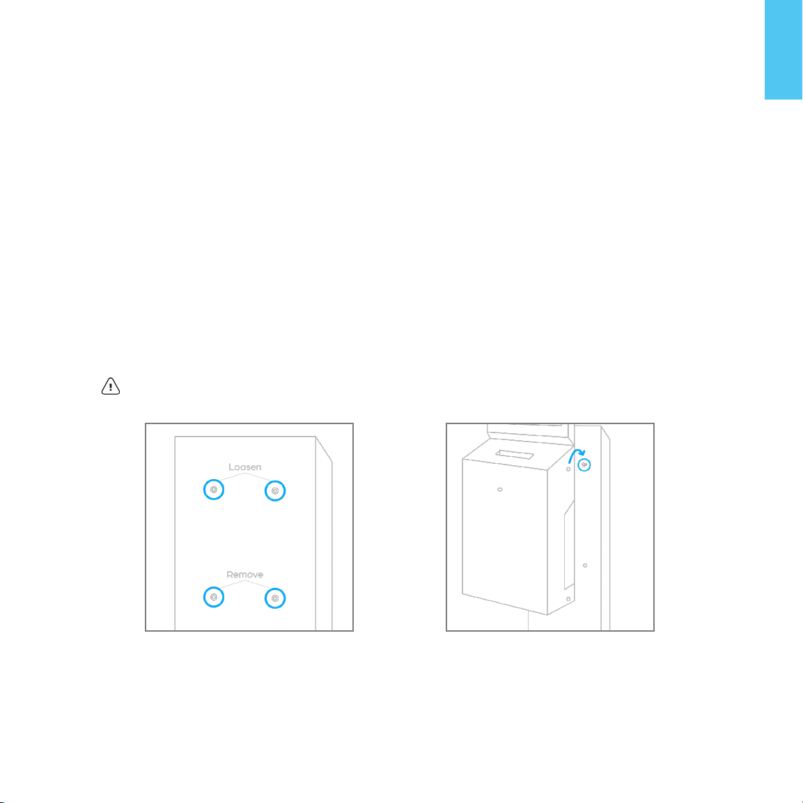
ON
On/Off
Switch Symbols
OFF

The iCleanse Swift UV provides chemical-free, general-purpose disinfection for
phones in just 15 seconds killing 99.99% of pathogens that can lead to sickness.
The Swift UV has been designed for minimal contact with both the user and
what you place in it, allowing maximum surface coverage by germicidal light
during the disinfection cycle.
Please read through this guide thoroughly to ensure proper use of your Swift UV.
Included Accessories
Purell®ES8 Hand Sanitizer Dispenser
Hand Sanitizer Mounting Plate
Swift UV Floor Stand
Wall Installation Power Cable
*Accessories included with your Swift UV will vary based on your order. Sanitizer
Fluid not included. Purell®P/N: 7751-02.
To purchase hand sanitizer please contact your distributor, or visit:
www.icleanse.com/refills to order.
Meet Your Swift UV
About Your iCleanse Swift UV
4

About Your iCleanse Swift UV
5
Tech Specs
Model Swift UV with Stand and
Sanitizer Dispenser Swift UV Wall-Mount
Dimensions 56.5 in x 23 in x 23 in / 143.5 cm x
58.4 cm x 58.4 cm
26 in x 10.75 in x 4 in / 66 cm x 27.3
cm x 10.1 cm
Weight 46 lbs / 20.8 kg 13 lbs / 5.9 kg
Phone Accommodations Any standard smart phone with standard case
Disinfection Cycle Time User Defined – Default is 15 seconds
Operating Temp. Range 37°F - 95°F / 2.78°C - 35°C
Operating Humidity Range 5-95% @ 82.4°F / 5-95% @ 28°C
Storage Humidity Range 0-95% Non-condensing
Operation Altitude Up to 6,561 ft / 2,000 m
AC Supply Voltage 120VAC - 240VAC
Frequency Rating 50/60HZ
Current Rating 1.8A/1A
Mains Supply Fluctuations +/- 10%
Fuse Type 2.5A, 250 VAC, 5mm x 20mm
Installation Requirements Level Surface; 3 in / 7.5 cm from
obstruction Flat Wall
Power Cord Length 6.5 ft / 2 m 12.5 in / 31.8 cm
Pollution Degree 2

About Your iCleanse Swift UV
6
This section describes the steps to be taken to assemble and install the device.
Included Hardware
Included Tools
Assembly and Installation of Your Swift UV
1x 5/32” Hex Wrench and
1x 1/8” Hex Wrench
Phillips Screwdriver
3/8” Open Ended Wrench
4x 1/2” Long Button
Head Hex Screws
2x 1/2” Long Round
Head Phillips Screws
6x 5/16” Long Button
Head Hex Screws
4x 5/8” Long Flat
Head Hex Screws
2x 3/8” Lock Nuts

7
About Your iCleanse Swift UV
Step 1: Lay the vertical stand on top of the shipping box with the iCleanse logo
facing up (Figure 01.).
Step 2: Take the baseplate marked “R” and align it to the right side of the stand,
also marked with an “R”.
Step 3: Use two of the provided 5/8” long flat head hex screws to securely
attach the right baseplate to the vertical stand (Figure 02.).
Step 4: Repeat steps 2 and 3 for the left side of the baseplate.
Step 5: Once both base plates are secure, stand the unit upright.
Assembling the Floor Stand
Figure 01. Figure 02.

Getting Started
8
Figure 03.
Step 6: To install the corner braces, remove the two pre-installed 5/16” long
button head hex screws on each side of the stand. Line up the two holes on each
brace with the two holes on each side of the stand and secure with the previously
removed screws (Figure 03.).
Note: The wider part should be flush to the bottom of the stand.

Getting Started
9
Mounting Swift UV to the Floor Stand
Figure 04. Figure 05.
Step 1: Remove the two lower 1/2” long button head hex screws on the face of
the stand and partially remove the two upper screws, leaving approximately
1/4” of the threading exposed (Figure 04.).
Step 2: Carefully hang the Swift UV on the two upper screws taking care to align
them with the two mounting points on the back of the Swift UV (Figure 05.).
Caution: Ensure that the Swift UV is fully seated on the two screws.

Getting Started
10
Figure 06. Figure 07.
Step 3: Loosen the two recessed screws on the right side of the Swift UV’s main
housing with the provided Phillips screwdriver and rotate the main housing
open (Figure 06.).
Step 4: Reinstall the lower right screw and tighten the two upper screws (Figure 07.).

Getting Started
11
Figure 08. Figure 09.
Step 5: Loosen the two thumb screws on the right side of the disinfection
chamber. Rotate the fan duct out (Figure 08.) then rotate the disinfection
chamber out to gain access to the back panel (Figure 09).

Getting Started
12
Step 6: Reinstall and tighten the final screw in the lower left corner then reach
into the access hole in the back of the Swift UV and plug the power cable into the
power inlet terminal (Figure 10.).
Step 7: Rotate the disinfection chamber and fan duct back into position and
secure the two thumb screws on the right side.
Figure 10.

Getting Started
13
Figure 11.
Step 8: Turn the power switch to the “ON” position (I) (Figure 11.).
Step 9: Close the main housing of the Swift UV and tighten the two recessed
Phillips screws.
Step 10: Plug the power cord into a grounded receptacle.

Getting Started
14
Step 1: Remove the two 5/16” long button head hex screws that are pre-installed
on the upper right side of the floor stand.
Step 2: Attach the hand sanitizer mounting plate with the two previously
removed screws (Figure 12.).
Attaching the Hand Sanitizer Mounting Plate
Figure 12.

Getting Started
15
To ensure the hand sanitizer is securely mounted, we recommend using the
fasteners provided with the Swift UV in addition to any adhesive backing that
may come with the hand sanitizer.
Align at least two mounting holes on the sanitizer with the holes in the
mounting plate.
Install the two 1/2” long round head Phillips screws through the hand sanitizer
and plate and secure with the lock nuts provided and tighten with the provided
Phillips screwdriver and 3/8” wrench.
Note: The Swift UV does not come with the hand sanitizer fluid. To purchase hand
sanitizer please contact your distributor, or visit: www.icleanse.com/refills to order.
Mounting the Hand Sanitizer

Getting Started
16
Note: This method requires roughed in electrical prior to installation which
must be centered 33.5” from the floor to comply with ADA requirements.
Please adhere to all local and national building codes when installing the wall
installation power cable.
Step 1: Use the supplied template to mark out where you will need to install your
roughed in electrical box and mounting hardware on the wall for proper installation.
Step 2: Use proper wall anchors or ensure proper depth screws are used when
mounting into wall studs. Note: Wall-mounting hardware is not included.
Wall Mounting the Swift UV

Getting Started
17
Step 3: Carefully hang the Swift UV on the two upper screws taking care to align
them with the two mounting points on the back of the Swift UV (Figure 13).
Caution: Ensure that the Swift UV is fully seated on the two screws.
Step 4: Loosen the two recessed screws on the right side of the Swift UV main
housing with the provided Phillips screwdriver and rotate the main housing
open (Figure 14.).
Step 5: Install the lower right screw and tighten the two upper screws (Figure 15.).
Figure 13. Figure 14. Figure 15.

18
Getting Started
Figure 16. Figure 17.
Step 6: Loosen the two thumb screws on the right side of the disinfection
chamber. Rotate the fan duct out (Figure 16.) then rotate the disinfection
chamber out to gain access to the back panel (Figure 17.).

19
Getting Started
Step 7: Install and tighten the final screw in the lower left corner in accordance
with the anchors being used (Figure 18.).
Step 8: Connect the power cord whip to the rough electrical within the junction box
and store any excess cabling in the junction box (Figure 19.).
Brown lead to line voltage (usually black or brown in color)
Blue lead to neutral wire (usually white or blue in color)
Green/yellow lead to the ground wire (usually bare copper or green in color)
Figure 18. Figure 19.
Table of contents
Other iCleanse Laboratory Equipment manuals
Popular Laboratory Equipment manuals by other brands

Ametek
Ametek SEQUOIA Series Programming manual

Mecmesin
Mecmesin Vortex operating instructions

Hettich
Hettich MIKRO 200 operating instructions

Lilly
Lilly Entuzity KwikPen Instructions for use

Sartorius Stedim Biotech
Sartorius Stedim Biotech BioSealer TC operating manual

Tanaka
Tanaka ACO-7 instruction manual

LW Scientific
LW Scientific ComboXL Centrifuge instruction manual

Mi Swaco
Mi Swaco 414 Installation, operation & maintenance manual

Hach
Hach TU5200 user manual

Biomeme
Biomeme Franklin three9 user manual

Four E's Scientific
Four E's Scientific Ironman operating instructions

Bruker
Bruker NMR 400 89 Ascend DNP user manual