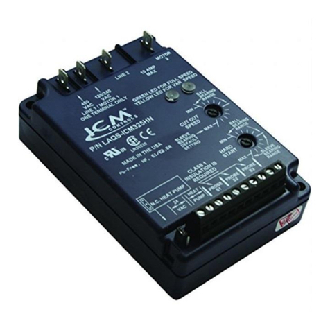
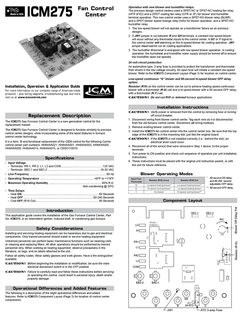
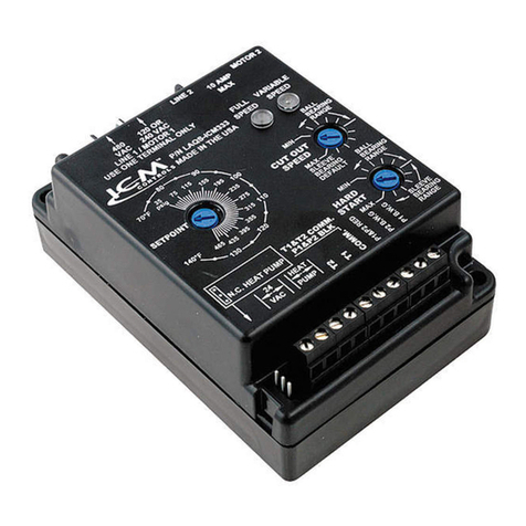
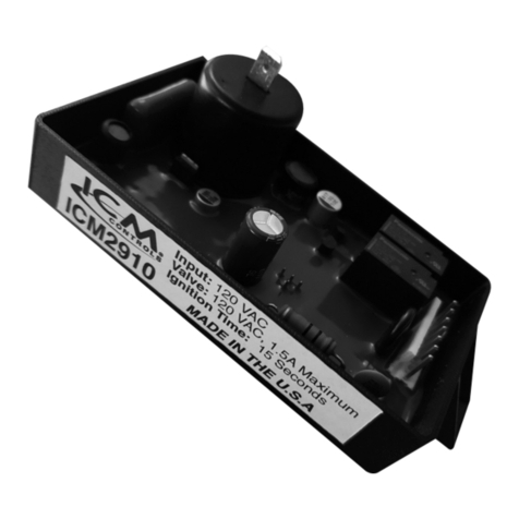
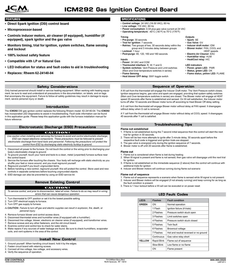
ICM Controls ICM325HN User manual

• Line voltage:120,208,240,and480VAC
• Control voltage:18-30VAC
• Frequency:50-60Hz
• Operating temperature:-40ºFto+176ºF(-40°Cto+75°C)
• Sensors:10Kohmsat77°F(25°C)
• Heat pump override:24VACN.C.orN.O.
Note:Amaximumofthreesensorscanbeconnectedtothecontrol.
• Weight:12ounces(341grams)
Note:The ICM325HN should be applied to motors and equipment that have been designated by their
respective manufacturers as capable of being speed controlled.
• Mounting:
– Surfacemountusing(4)#8screws
– TheICM325HNshouldbesurfacemountedtoacleanmetalorotherthermallyconductivesurfacefor
maximumheatdissipation
– ItisrecommendedthattheICM325HNbemountedawayfromthecondenserexhaustairinordertomaintain
loweroperatingtemperatures
Specifications
Installation of the ICM325HN shall be performed by trained technicians only. Adhere to all local and national
electric codes.
Disconnect all power to the system before making any connections.
Caution!
ICM325HN
Installation, Operation & Application Guide
For more information on our complete range of American-made
products – plus wiring diagrams, troubleshooting tips and more,
visit us at www.icmcontrols.com
Head Pressure
Control with
Optional
Heat Pump Override
Temperature sensitive
control regulates
head pressure
1. Removepowerfromsystem.
2. FieldinstallawirefromLine 1wiretoLine 1terminal.
3. CutLine2wire;afxmotorsidetoMotor2terminalandline
sidetoLine2terminal.
4. Make24VAC,probeandHPconnections.
5. Verifywiringiscorrect.
6. Powerupsystemandcheckoperation.
Connections for ICM325HN at 480 VAC
PSC
Fan
Motor
Run
Capacitor
480VAC
Typical condenser fan
Line
1
480VAC
Line
2
Motor
2
PSC
Fan
Motor
Run
Capacitor
480VAC
Field
Installed
Wire
Typical condenser
fanwithICM325HN
installed
Connections for ICM325HN at 120/208/240 VAC
1. Removepowerfromsystem.
2. FieldinstallawirefromLine 1wiretoLine 1terminal.
3. CutLine2wire;afxmotorsidetoMotor2terminalandline
sidetoLine2terminal.
4. Make24VAC,probeandHPconnections.
5. Verifywiringiscorrect.
6. Powerupsystemandcheckoperation. PSC
Fan
Motor
Run
Capacitor
Line
1
120/240
VAC
Line
2
Motor
2
PSC
Fan
Motor
Run
Capacitor
Field
Installed
Wire
Typical condenser
fanwithICM325HN
installed
120/208/240
VAC
Typical condenser fan
120/208/240
VAC
Connecting the Probe
Example
1. Installthetemperatureprobeseveralbendsintothecondenser.Itcanbeattachedtothe
U-bendorplacedbetweenthensintheupper1/3ofthecondenser(seeothersidefor
moreinformation).
Note:
Theresponseofthesystemcanbenetunedbyrepositioningtheprobe.Place
theprobeonthecondenserwhereitis100°Fwhenpressuresarecorrectfor
bestresponse.
2. Connectthetwowiresfromthesensortotheterminal
blockwhereitismarkedPROBE S1.Ifadditionalprobesarenecessaryformultiple
refrigerantcircuits,theymaybeattachedtoterminalsmarkedPROBES2andPROBES3.
Note:
Thecontrolwillrespondtotheprobethatsensesthehighesttemperature.
Connections for Air Conditioning Only
1. For non-heat pump applications,theheat
pumpselectjumpermustbeintheDefault
(N.O.)position,andtheHPterminalsmust
beleftunconnected.
2. SettheCutout SpeedandtheHard Start
Timetotheappropriatepositionsforthetype
ofmotoryouhave(seeotherside).
TemperatureProbe24VAC
Additional
Probes
ProbeS1
HP
HeatPump
SelectJumper
DefaultPosition
ICM325HN Typical Installation

Thecutoutspeeddialadjuststhemotorvoltagerange.Setthecutout
voltagedialaccordingtothetypeofmotoryouhave.
Sleeve Bearing Motors:
Setthecutoutspeeddialtothemiddleofthesleevebearingrange.In
thisrange,themotorcanrundownapproximately40-50%ofthefullline
voltage,whichallowssufcientRPMsforcoolingandlubrication.
CAUTION!:
Withsleevebearingmotors,itisimportantnottoadjust
outsidethesleevebearingrangeorbearingfailuremayresult.
Ball Bearing Motors:
SetthecutoutspeeddialtotheMINpositionintheballbearingrange.Thispositionoffersthegreatestrangeof
speedcontrol.AttheMINsettingthemotorcanrundowntoapproximately20-30%ofthefulllinevoltage.
Note:After starting at the recommended settings for either sleeve or ball bearing motors, you can ne tune the
cutout speed to achieve the desired results.
1. TheHeat Pumpterminalsacceptthe24VACsignalfromthereversingvalveholdingcoil.Makeaparallel
connectionfromthereversingvalvetotheHPterminals.
Note: Do not apply a voltage higher than 30 VAC to the HP terminals.
2. IftheHeat PumpisintheHeatingmodeandthereversingvalveisenergized,thentheHeat Pump
SelectjumpermustbeintheDefault(N.O.)position.
3. IftheHeat PumpisintheHeatingmodeandthereversingvalveisnotenergized,thentheHeat
Pump SelectjumpermustbeintheN.C.position.
Connections for Heat Pump Systems
N.O.
N.C.
Temperature
Probe
24VAC ConnectParallelto
24VACReversingValve
Additional
Probes
ProbeS1
HP
HeatPump
SelectJumper
DefaultPosition
Normal Function
Withprobetemperaturesabove100°F,thecontrolappliesfullvoltagetothemotor.Thegreenlightisilluminated(full
speedLED).
Withprobetemperaturesbetween70°Fand100°F,themotorspeedisproportionaltotheprobetemperature.The
yellowlightisilluminated(variablespeedLED).
Whenthemotorstartsattemperaturesbetween70°Fand100°F,itwillhardstartforthelengthoftimedictated
bythehardstartdialsetting.Afterthehardstarttimehaselapsed,themotorspeediscontrolledbytheprobe
temperature.
Asthetemperaturebeingsenseddecreases,theoutputvoltagedecreases.Theoutputvoltagemaydecreaseto
thedeterminedcutoutspeeddictatedbythecutoutspeeddial.Uponreachingthecutoutspeedsetting,theoutput
voltagegoestozerovolts.
Systemrestartwilloccurwhenthetemperatureexceeds70°F.
Withprobetemperaturesbelow70°F,themotorremainsoff.Thegreenlightandtheyellowlightareoff.
Heat Pump Bypass Operation
Heatpumpbypassmoderunsthefanatfullspeedwhenthesystemisoperatinginheatmode.Thismovesasmuch
airaspossibleacrossthecondensercoil.
IftheheatpumpselectjumperisintheN.O.position,and24VACisappliedtotheHPterminals,themotorwillbe
broughttofullspeed.
IftheheatpumpselectjumperisintheN.C.position,and24VACisnotpresentattheHPterminals,themotorwill
bebroughttofullspeed.
Aseparaterelayisnotneeded.
Mode of Operation
Setting the Hard Start Time
DuringtheHard Startmode,fullvoltageisappliedtothemotorduringstartupto
overcomewindmillingandtolubricatethebearings.
Thepositionofthehardstartdialdeterminesthetimeperiodofthehardstartmode.
Thedialcanbeadjustedbetween0.1secondandapproximately5seconds.
Setthehardstartdialaccordingtothetypeofmotoryouhave.Ifyouhaveaball
bearing motor,setthehardstartdialtotheMINposition.Ifyouhaveasleeve
bearing motor,setthehardstartdialtothemiddleofthesleevebearingrange.
Afteryoubeginattherecommendedsetting,youcannetunethehardstarttime
withintherecommendedrangeforthetypeofmotoryouhave.
Itisrecommendedthatyouusetheminimumpossiblehardstarttimetoavoid
blowingtoomuchcoldairoverthecondenser.
Hard Startmodeisactivatedwhen24VACisapplied(ordisconnectedandre-applied)ortheprobetemperature
increasestoabove70°F.Thehardstartmodeappliesfullvoltagetothemotorforthesettimeperiod.Afterwards,the
motorspeedisdictatedbythetemperaturesensor(s).
Symptom Problem
Unitfailstostart Thesensormaynotbeconnectedoritisdefective.
Withtheprobedisconnected,useanohmmetertomeasuretheresistancebetweenthe
probewires.ItshouldmatchthechartinAppendixB(seebelow).IfyoureadanOPENor
SHORT,replacethesensor.
Fuseand/or
circuitblows
Theunithasbeenmiswiredandmaybepermanentlydamaged.
Thefancycles
fromfullONtofull
OFFwithlittleor
nomodulation
TurnOFFthecontrolcircuitpower(24VAC).Re-apply24VACpowerandconrmhardstart
operation.Reducethehardstartperiodtotheminimumsettingrequiredtoacceleratethe
fan.Excessivehardstartingcauseslargepressuredropsbyrunningtoomuchcoldairover
thecondenser.
Shouldthecyclingpersist,movetheprobeupseveralbendsintothecondensertoincrease
thesensitivitytocondensingtemperature.
Adjustprobelocation.Finetunecutoutadjustment.
Thefandoesnot
comeonatall
UsinganACvoltmeter,measurethevoltagebetweenthe24VACterminals.Itshouldread
approximately24volts.
MeasurethelinevoltagebetweenLINE 1andLINE2toconrmthatthelinevoltageis
present.
Removethethermistorprobefromtheterminalblockandmeasureitsresistanceatambient
temperature.CompareyourreadingattheappropriatetemperatureinAppendixB(seePage
9)toseeiftheactualresistanceapproximatesthelistedvalue.Next,holdtheprobeinyour
handandconrmthattheresistancedecreases.
PlaceatemporaryjumperacrosstheS2orS3terminals.Fanshouldrunatfullspeed.Ifit
does,recheckprobeconnectionandverifyprobeisoperatingcorrectly.
Thehighpressure
switchtripsoff
Movetheprobefurtherintothecondenserwherethetemperatureishigher.Thiswillproduce
ahigherfanRPMandwilldecreasetheheadpressure.
Fineadjustthecutoutandhardstartsettings.
Greenandyellow
LEDsalternate
UsinganACvoltagemeter,measurethevoltagebetweenthe24VACterminals.
AlsoverifyyouhavethevoltagebetweenLine 1andLINE2terminals.
Troubleshooting
Mountingasensorintothecondenser
vs. mounting it on the liquid line
Whenasensorismountedintothecondenser,the
controlrespondsmorerapidlytochangesinhead
pressurethanwhenitismountedontheliquidline.This
isespeciallytrueforhighefciencycondensers.
Whenthesensorismountedontheliquidline,the
controlrespondsmoreslowlyandtheresultscanbea
fanthatcyclesonandoff.
Wheneverpossible,itispreferabletomountthesensor
intheupper1/3ofthecondenserinsteadofmountingit
ontheliquidline(seeillustrationbelow).Aspotonthe
condenserthatis100Fwhenthepressuresarecorrect
isideal.
Temperature vs. Probe Resistance
°C °F Resistance (KΩ)
0° 32° 32.7
5° 41° 25.4
10° 50° 19.9
15° 59° 15.7
20° 68° 12.5
25° 77° 10.0
30° 86° 8.1
35° 95° 6.5
40° 104° 5.3
45° 113° 4.4
50° 122° 3.6
Appendix A Appendix B
Setting the Cutout Speed
ONE-YEAR LIMITED WARRANTY
TheSellerwarrantsitsproductsagainstdefectsinmaterialorworkmanshipforaperiodofone(1)yearfromthe
dateofmanufacture.TheliabilityoftheSellerislimited,atitsoption,torepair,replaceorissueanon-casecreditfor
thepurchasepricesofthegoodswhichareprovidedtobedefective.Thewarrantyandremediessetforthherein
donotapplytoanygoodsorpartsthereofwhichhavebeensubjectedtomisuseincludinganyuseorapplication
inviolationoftheSeller’sinstructions,neglect,tampering,improperstorage,incorrectinstallationorservicingnot
performedbytheSeller.InordertopermittheSellertoproperlyadministerthewarranty,theBuyershall:1)Notify
theSellerpromptlyofanyclaim,submittingdatecodeinformationoranyotherpertinentdataasrequestedbythe
Seller.2)PermittheSellertoinspectandtesttheproductclaimedtobedefective.Itemsclaimedtobedefective
andaredeterminedbySellertobenon-defectivearesubjecttoa$30.00perhourinspectionfee.Thiswarranty
constitutestheSeller’ssoleliabilityhereunderandisinlieuofanyotherwarrantyexpressed,impliedorstatutory.
Unlessotherwisestatedinwriting,Sellermakesnowarrantythatthegoodsdepictedordescribedhereinaretfor
anyparticularpurpose.
LIAF042
PatentNo.424,953
7313WilliamBarryBlvd.,NorthSyracuse,NY13212
(Toll Free)800-365-5525(Phone)315-233-5266(Fax)315-233-5276
www.icmcontrols.com
Other manuals for ICM325HN
1
Table of contents
Other ICM Controls Control Unit manuals

ICM Controls
ICM Controls ICM281 User manual

ICM Controls
ICM Controls ICM275 User manual

ICM Controls
ICM Controls ICM325HN General instructions

ICM Controls
ICM Controls ICM292A User manual

ICM Controls
ICM Controls ICM333 General instructions

ICM Controls
ICM Controls ICM2813 General instructions

ICM Controls
ICM Controls ICM291 User manual

ICM Controls
ICM Controls ICM2910 General instructions

ICM Controls
ICM Controls ICM281 User manual

ICM Controls
ICM Controls ICM288 User manual