manuals.online logo
Brands
  1. Home
  2. •
  3. Brands
  4. •
  5. ICM Controls
  6. •
  7. Control Unit
  8. •
  9. ICM Controls ICM281 User manual

ICM Controls ICM281 User manual

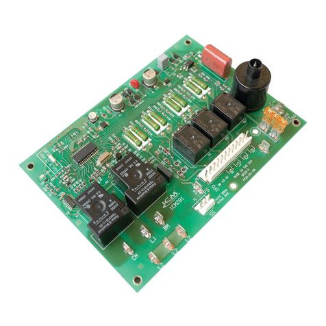
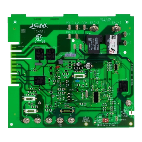
ICM281
Fixed Speed Furnace Control Replacement Module
Replaces: Carrier CESO110057-00, CESO110057-01, CESO110057-02
Safety Considerations
Only trained personnel should install or service heating equipment.
When working with heating equipment, be sure to read and
understand all precautions in the documentation, on labels, and
on tags that accompany the equipment. Failure to follow all safety
guidelines may result in damage to equipment, severe personal
injury or death.
Introduction
The ICM281 xed speed furnace control replaces the following
Carrier/BDP modules: CESO110057, CESO110057-1,
CESO110057-2, CESO110048, CESO110020, and HH84AA016
The ICM281 has incorporated LED diagnostics to assist in
troubleshooting.
It is recommended that a sight glass (not included) be installed
in a convenient location on the furnace to take advantage of this
feature. If a sight glass is not installed, the self-test feature of the
board can still be used for routine troubleshooting. A fault code label
is included in this package and must be installed on the furnace.
Electrostatic Discharge (ESD) Precautions
CAUTION!
Use caution when installing and servicing the furnace to avoid
and control electrostatic discharge; ESD can impact electronic
components. These precautions must be followed to prevent
electrostatic discharge from hand tools and personnel. Following
the precautions will protect the control from ESD by discharging
static electricity buildup to ground.
1. Disconnect all power to the furnace. Do not touch the control
or the wiring prior to discharging your body’s electrostatic
charge to ground.
2. To ground yourself, touch your hand and tools to a clean,
metal (unpainted) furnace surface near the control board.
3. Service the furnace after touching the chassis. Your body
will recharge with static electricity as you shufe your feet or
move around, and you must reground yourself.
4. Reground yourself if you touch ungrounded items.
5. Before handling a new control, reground yourself; this will
protect the control. Store used and new controls in separate
containers before touching ungrounded objects.
6. ESD damage can also be prevented by using an ESD service
kit.
CAUTION!
Failure to turn off gas and electric supplies can result in
explosion, re, death, or personal injury.
6. Disconnect thermostat wires and humidier wires (if equipped
with a humidier).
7. Disconnect line voltage, blower, electronic air cleaner wires (if
equipped), and transformer wires.
8. Remove wiring harness edge connector and gasket from
circuit board.
9. Remove screws or any other fasteners and old circuit board.
10. Examine control and control box to check for water stains.
11. Make repairs if any sources of water leakage are found.
Be sure to check humidiers, evaporator coils, and vent
systems in the area of the control.
Step 2: Install the New Control
1. Ground yourself. When handling circuit board, hold it by the
edges.
2. For 90 percent efcient furnaces, clip JW9 jumper wire. The
JW9 jumper is found close to the right hand corner of the
circuit board, beneath the HUM-1 terminal (see Figure 1).
This will result in a 15-second inducer OFF delay.
3. Insert board’s edge between control box tabs.
4. Fasten circuit board with retaining screws.
IMPORTANT:
For 58EJA or 349MAV horizontal furnaces, the bottom control
board bracket may need to be notched and trimmed to pre-
vent the LED and circuit trace from interfering with the mount-
ing bracket. This may cause a short and result in damage to
the control.
To prevent:
a. Remove the mounting bracket from the control box.
b. Mark, notch and trim the bracket between where the
bottom center and bottom right mounting holes/pins align.
Be sure to trim enough of the bracket so the circuitry on
the underside of the control board lies clear of the bracket.
Step 1: Remove Existing Control
CAUTION!
To service control, and prior to disconnection, label all wires.
Failure to do so may result in wiring errors can cause dangerous
operation.
1. Turn thermostat to OFF position or set it to the lowest
possible setting.
2. Turn OFF electrical supply to furnace.
3. Turn OFF gas supply to furnace.
4. Remove furnace blower and control access doors.
5. Remove control box cover.
• Controls gas valve, ignitor, blower motor, inducer, humidifier and air cleaner
• Microprocessor-based
• Designed for 100% gas shutoff in case of ignition failure
• Twinning compatible with other ICM281 boards
• Reverse polarity protection
• Secondary brownout voltage protection
• Compatible with 24 VAC standard thermostat
• Provides diagnostic LED to aid in troubleshooting
Specifications
Electrical
• Voltage Range: Line (98 to 132 VAC) @ 60Hz
• Ignitor: 5A @ 120 VAC
• Cool Blower: 30A, 2HP, 240 VAC
• Heat: 5A, 1/2 HP, 240 VAC
• Inducer Motor: 4A, FLA-8.0 LRA @ 120 VAC
• Gas Valve: 1.5A @ 30 VAC
Features
LIA231-2
2
1
Bottom Right Corner of Control Board
c. Verify clearance by mounting the control board on the
bottom of the support rail.
d. If clear, remove the bottom mounting bracket from the
control board and re-attach the bracket to the control box.
e. Install the control board into the control box by sliding the
mounting tab on the control board through the slots in the
top of the control box.
f. Attach the control board to the bottom mounting rail of the
furnace control box.
g. Continue on to Step-5 of the installation process.
5. Connect all line voltage, low voltage, and accessory wires.
6. Connect wiring harness edge connector to circuit board.
7. Set blower off delay. Blower off delay DIP switch SW1 is
found near the right-hand corner of the board (see Figure 1).
8. Re-install control box cover.
Note: Do not connect thermostat wires to control board until
system tests are complete.
System Tests
Step 1: Component Self Test
1. Begin component test sequence by ensuring that thermostat
is turned to OFF position and thermostat wires are
disconnected. Turn power ON and engage blower door
switch. With a short piece of wire, briey short TEST/TWIN
terminal to Com/24V terminal. The component test sequence
follows:
A. Status LED will ash code and will then turn ON the
inducer motor.
B. Inducer motor will run for the entire component test.
C. Hot surface ignitor and blower motor heat speed will run
for 10 secs.
D. Blower motor cool speed will turn ON for 10 secs.
2. Repair, replace, or service any failing components from the
component self test. The gas valve is not energized during
the self test.
3. Turn power OFF.
4. Disengage the blower door switch.
5. Connect thermostat wires.
6. Install blower door and access door.
7. Turn power ON.
8. Turn gas ON.
Step 2: Flame Sensor Operation
Connect a DC microammeter in series with ame sensor.
Initiate a heat call. After burners ignite and stabilize, measure
ame current. Nominal ame current is between 2.0 and
4.0 microamps DC. If ame current reading is less than 2.0
microamps DC, either replace or remove and clean ame sensor
with a ne grade steel wool. When the ame current falls to 0.5
microamps DC, the furnace control will lock out.
Step 3: System Operation
1. Perform necessary safety checks. Consider ame safety, limit
switch, and vent system.
2. Operate unit through a complete call for heat cycle.
Upow Condensing Furnaces:
With the blower door(s) removed, locate the LED on the control
board. Check the sides of the casing. You may be able to utilize
the unused condensate drain opening or electrical knock-out as an
observation port on some models. A 1/2-inch electrical box knock-
out plug must be installed when this option is used.
All Furnaces:
1. Measure the height of the oor for upow furnaces or off the
blower shelf on downow/horizontal furnaces.
2. Measure the distance from the front inside edge of the casing.
3. Orient the blower door to the correct position and mark this
location on the front of the blower door.
4. Using a step-drill or chassis punch, drill a 1 1/2-inch hole in
the blower door.
5. Install a sight glass in the blower door (Use Carrier Part No.
323017-201 or 323018-201, or equivalent).
6. A 1/2 inch hole may be drilled and an electrical box plug may
be used and are available from hardware stores or electrical
suppliers.
Note: Do not install an observation port or sight glass through
warning labels on furnace.
CAUTION!
A loose tting sight glass should be sealed with clear silicone to
prevent leakage and sight glass from falling out.
7. Install Fault Code Label in a convenient location on the
blower door adjacent to the sight glass.
CAUTION!
Do not install a sight glass or observation port between the
furnace and the blower compartment. To avoid having carbon
monoxide drawn into the living area, do not cover any port with
tape, and do not leave the unit unattended and operational with
the blower door off. Failure to follow this warning could result in
possible damage to this equipment, serious illness or personal
injury, or death.
Note: If a sight glass is not installed, current fault code will be
erased when blower door is removed.
The ICM281 furnace control has LED fault code capability. To
utilize this feature, it is necessary to eld install a sight glass or
observation port. The location of this device will vary depending on
the model of the furnace.
Optional Observation
Port/Sight Glass Installation
Twinning Instructions
A 3/16” quick connect terminal is provided on the ICM281 control
board for communication between another ICM281 control board
for furnace twinning.
To congure your control boards for twinning, simply (1) install
each control board according to the installation instructions; (2)
connect the TWIN terminals together (see Fig. 1); and (3) connect
the 24 VAC common together. A common ground between the two
furnaces is also required.
If the 24 VAC supplies to the control are in phase, both furnaces will
turn the blower on and off synchronously and at the same speed.
If the 24 VAC supplies are not in phase, then neither control will
respond to the thermostat commands and the status LED will ash
rapidly.
Figure
1

Other ICM Controls Control Unit manuals

ICM Controls ICM333 General instructions

ICM Controls

ICM Controls ICM333 General instructions

ICM Controls ICM325HN User manual

ICM Controls

ICM Controls ICM325HN User manual

ICM Controls ICM325HN General instructions

ICM Controls

ICM Controls ICM325HN General instructions

ICM Controls ICM291 User manual

ICM Controls

ICM Controls ICM291 User manual

ICM Controls ICM330 General instructions

ICM Controls

ICM Controls ICM330 General instructions

ICM Controls ICM288 User manual

ICM Controls

ICM Controls ICM288 User manual

ICM Controls ICM281 User manual

ICM Controls

ICM Controls ICM281 User manual

ICM Controls ICM275 User manual

ICM Controls

ICM Controls ICM275 User manual

ICM Controls ICM326H User guide

ICM Controls

ICM Controls ICM326H User guide

ICM Controls ICM292A User manual

ICM Controls

ICM Controls ICM292A User manual

ICM Controls ICM292 User manual

ICM Controls

ICM Controls ICM292 User manual

ICM Controls ICM2910 General instructions

ICM Controls

ICM Controls ICM2910 General instructions

ICM Controls ICM2813 General instructions

ICM Controls

ICM Controls ICM2813 General instructions

Popular Control Unit manuals by other brands

Ebyte E108-GN Series user manual

Ebyte

Ebyte E108-GN Series user manual

Pentek 4200A operating manual

Pentek

Pentek 4200A operating manual

Giant Alarm System 3010-1A user manual

Giant Alarm System

Giant Alarm System 3010-1A user manual

Beckhoff KM2002 Documentation

Beckhoff

Beckhoff KM2002 Documentation

Helo WE 40 User and installation manual

Helo

Helo WE 40 User and installation manual

National Instruments NI 9269 Getting started guide

National Instruments

National Instruments NI 9269 Getting started guide

Sony CCP-6224 CCP-6324 MKS-8010B MKS-8011AMKS-8013A MKS-8014A MKS-8015A MKS-8017AMKS-8018A MKS-8019A MKS-8020A... Operation manual

Sony

Sony CCP-6224 CCP-6324 MKS-8010B MKS-8011AMKS-8013A MKS-8014A MKS-8015A MKS-8017AMKS-8018A MKS-8019A MKS-8020A... Operation manual

Miele DOS G 80 Fitting instructions

Miele

Miele DOS G 80 Fitting instructions

Beninca CP.MBE24 manual

Beninca

Beninca CP.MBE24 manual

EKE-Electronics EKE-Trainnet MVB2791B Technical manual

EKE-Electronics

EKE-Electronics EKE-Trainnet MVB2791B Technical manual

Honeywell Braukmann T100A Product data

Honeywell

Honeywell Braukmann T100A Product data

Grundig GSS SID 162 Assembly instruction

Grundig

Grundig GSS SID 162 Assembly instruction

INAZUMA WebCSA Series operating instructions

INAZUMA

INAZUMA WebCSA Series operating instructions

UNICORECOMM UM960 user manual

UNICORECOMM

UNICORECOMM UM960 user manual

Fibocom L811-EA Series Hardware user manual

Fibocom

Fibocom L811-EA Series Hardware user manual

Nordson EFD Liquidyn P-Jet SolderPlus operating manual

Nordson EFD

Nordson EFD Liquidyn P-Jet SolderPlus operating manual

DEUTSCHMANN AUTOMATION LOCON 200 instruction manual

DEUTSCHMANN AUTOMATION

DEUTSCHMANN AUTOMATION LOCON 200 instruction manual

VAT 570 Series Installation, operating,  & maintenance instructions

VAT

VAT 570 Series Installation, operating, & maintenance instructions

manuals.online logo
manuals.online logoBrands
  • About & Mission
  • Contact us
  • Privacy Policy
  • Terms and Conditions

Copyright 2025 Manuals.Online. All Rights Reserved.