manuals.online logo
Brands
  1. Home
  2. •
  3. Brands
  4. •
  5. ICM Controls
  6. •
  7. Thermostat
  8. •
  9. ICM Controls MP5010 General instructions

ICM Controls MP5010 General instructions

Package Contents/Tools Required
Package includes:MP5010 PROthermostatonbase,thermostatcover,wiringlabels,screwsandwallanchors,2
“AAA”batteries,Installation,OperationandApplicationGuide
Tools required for installation:Drillwith3/16”bit,hammer,screwdriver
To Remove Existing Thermostat
ELECTRICAL SHOCK HAZARD
– Turn off power at the main service panel by removing the fuse
or switching the appropriate circuit breaker to the OFF position before removing the existing
thermostat.
1. Turnoffpowertotheheatingandcoolingsystembyremovingthefuseorswitchingtheappropriatecircuit
breakeroff.
2. Removecoverofoldthermostat.Thisshouldexposethewires.
3. Labeltheexistingwireswiththeenclosedwirelabelsbeforeremovingwires.
4. Afterlabelingwires,removewiresfromwireterminals.
5. Removeexistingthermostatbasefromwall.
6. Refertothefollowingsectionforinstructionsonhowtoinstallthisthermostat.
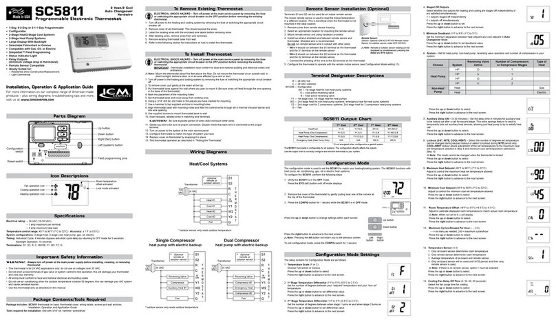
Parts Diagram
Congurationswitch
Resetswitch
Fieldprogrammingpins
RC/RHJumper
RCGW
O/B
YS2S1 CRH
CONFIGRESET
FP
RC
RH
Icon Descriptions
Coolingoperationicon
Fanoperationicon
Heatingoperationicon
Lockmodeactivated
Roomtemperature
offsetactivated
Important Safety Information
WARNING!
:
Always turn off power at the main power supply before installing, cleaning, or removing
thermostat.
• Thisthermostatisfor24VACapplicationsonly;donotuseonvoltagesover30VAC
• Donotshortacrossterminalsofgasvalveorsystemcontroltotestoperation;thiswilldamageyourthermostat
andvoidyourwarranty
• Allwiringmustconformtolocalandnationalelectricalandbuildingcodes
• Donotuseairconditioningwhentheoutdoortemperatureisbelow50degrees;thiscandamageyourA/Csystem
andcausepersonalinjuries
• Usethisthermostatonlyasdescribedinthismanual
Specifications
Electrical rating:•24VAC(18-30VAC)
 •3.0VDC(2“AAA”batteries)
 •1ampmaximumperterminal
 •3ampmaximumtotalload
Temperature control range: 45°Fto90°F(7°Cto32°C)Accuracy:±1°F(±0.5°C)
System congurations:1-stageheat,1-stagecool,heatpump,gas,oil,electric
Timing:
Anti-shortCycle:
4minutes
 BacklightOperation:5secondswhenconguredON
Terminations:S1,S2,Y,W/O/B,G,RC,RH,C
Hardwired
5-Wire, Two Transformer
(Both transformers must be in phase)
Hardwired
4 or 5-Wire, Single Transformer
Fan
Control
IMPORTANT:Beforewiring,removepre-installed
RC/RHjumper.
To Install Thermostat
ELECTRICAL SHOCK HAZARD
– Turn off power at the main service panel by removing the fuse
or switching the appropriate circuit breaker to the OFF position before removing the existing
thermostat.
IMPORTANT:Thermostat installation must conform to local and national building and electrical codes and
ordinances.
Note:Mount the thermostat about ve feet above the oor. Do not mount the thermostat on an outside wall, in
direct sunlight, behind a door, or in an area affected by a vent or duct.
1. Turnoffpowertotheheatingandcoolingsystembyremovingthefuseorswitchingtheappropriatecircuit
breakeroff.
2. Toremovecover,pullgentlyattheseamatthetop.
3. Putthermostatbaseagainstthewallwhereyouplantomountit(Besurewireswillfeedthroughthewireopening
inthebaseofthethermostat).
4. Marktheplacementofthemountingholes.
5. Setthermostatbaseandcoverawayfromworkingarea.
6. Usinga3/16”drillbit,drillholesintheplacesyouhavemarkedformounting.
7. Useahammertotapsuppliedanchorsinmountingholes.
8. Alignthermostatbasewithmountingholesandfeedthecontrolwiresthroughslitinthermalintrusionbarrierand
intowireopening.
9. Usesuppliedscrewstomountthermostatbasetowall.
10. Insertstripped,labeledwiresinmatchingwireterminals.

CAUTION!
:Be sure exposed portion of wires does not touch other wires.
11. Gentlytugwiretobesureofproperconnection.Doublecheckthateachwireisconnectedtotheproper
terminal.
12. Insert2“AAA”batteriesintobatteryholder.Orientthemintheproperdirection.
13. Turnonpowertothesystematthemainservicepanel.
14. Congurethermostattomatchthetypeofsystemyouhave.
15. Replacecoveronthermostatbysnappingitinplace.
16. Testthermostatoperationasdescribedin“TestingtheThermostat”.
Wiring Diagrams
Hardwired
3-Wire, Single Transformer
Hardwired
4-Wire, Single Transformer
* Commonwireconnection
optionalwithbatteries
installed.
Hardwired – Cool or Heat Active Reversing Valve
Hardwired – 4-Wire, Single Transformer
Configuration Mode Settings
ThesetupscreensforCongurationModeareasfollows:
2. Temperature Differential (1°F to 5°F) (0.5°C to 2.5°C) –Setthenumberofdegrees
betweenyour“setpoint”temperatureandyour“turnon”temperature.
 Presstheupordownbuttontosetdifferentialvalue.
 Presstheright buttontoadvancetothenextscreen.
1. Temperature Scale (F or C) –ChooseFahrenheitorCelsius.
 Presstheupordownbuttontoselect.
 Pressthe
right
buttontoadvancetothenextscreen.
3. Deadband (1°F - 9°F) (1°C - 5°C) –Settheminimumnumberofdegreesbetweenyour
heatsettemperatureandyourcoolsettemperatureinAutochangeovermode.
 Presstheupordownbuttontosetdeadbandvalue.
 Presstherightbuttontoadvancetothenextscreen.
Installing and Changing Batteries
IfyourLCDisblank,ordisplayingLO BAT,thebatteriesarenotinstalledorneedtobechanged.Wesuggestyou
changethebatteriesatleastonceayear,orwhenevertheLO BAT warningdisplays.
Removethecover,andinstallthetwo“AAA”alkalinebatteriesintothebatterycompartment.Properbattery
installationisimportant!Makesurethepositiveendsofthebatteriesmatchthepositiveterminalsinthebattery
compartment.
Batterieswillprovidepowertomaintaintheclockduringapowerloss.
Configuration Mode
OFF
PM
1. VerifytheMP5010isintheOFFmode.
 PresstheSYS(left)buttonuntiloffmodedisplays.
ThecongurationmodeisusedtosettheMP5010tomatchyourheating/coolingsystem.TheMP5010functions
withheatpump,airconditioning,gas,oilorelectricheatsystems.
ToconguretheMP5010,performthefollowingsteps:
2. Removethecoverofthethermostatbygentlypullingnearoneofthe
cornersatthetopofthethermostat.
Note:Do not force open. Use a small coin or slotted screwdriver to release tabs if necessary.
Presstheupordownbuttontochangesettingswithineachscreen.
Down
button
Up
button
Toexitcongurationmode,presstheCONFIGswitchfor1second.
Presstherightbuttontoadvancetothenextscreen.
Note:Pressing the
left
button will return you to the previous screen. Left
button
Right
button
3. PresstheCONFIGbuttonfor1secondwhiletheMP5010isinOFF mode.
CONFIG
Choose System
Reversing
Valve Active
Number of Com-
pressors
Type of
Heat
Heat Pump HP O 1
HP b 1
Non-Heat
Pump
Heat Gas
Heat Electric
Presstheupordownbuttontoselect.
Presstherightbuttontoadvancetothenextscreen.
4. System –Setforheatpump,non-heatpump,reversingvalveoperationandnumberofcompressorinyour
system.
* Commonwireconnection
optionalwithbatteries
installed.
* Commonwireconnection
optionalwithbatteries
installed.
7. Room Temperature Offset(+9°Fto-9°F)(+4.5°Cto-4.5°C)
 Adjusttocalibratedisplayedroomtemperaturetomatchactualroomtemperature
(must be adjusted before permanent lock).
Note:When not set to 0, will display
 Presstheupordownbuttontoselect.
 Presstherightbuttontoadvancetothenextscreen.
10. Temperature Sensor(1-4)
 1. Onlyon-boardsensordeterminesroomtemperature.
 2. Onlyremotesensordeterminesroomtemperature.
 3. Averagetemperatureofon-boardandremotesensor.
 4. Onlyon-boardsensorwillbeuseduntilNITEperiod,andthenonlyremotesensor
isused.
 Presstheupordownbuttontoselect.
 Presstherightbuttontoadvancetothenextscreen.
1.Removecoverfromremotesensorhousing.
2.Selectanappropriatelocationformountingtheremotesensor.
3.Mountremotesensorunitusinghardwareprovided.
4.Installtwostrandshieldedwirebetweenremotesensorandthermostat.Shieldedwiremustbeused.Do notrun
remotesensorwireinconduitwithotherwires.
 •Wire 1shouldrunbetweentheS1terminalonthe
thermostatandtheS1terminalontheremotesensor
 •Wire 2shouldrunbetweentheS2terminalonthe
thermostatandtheS2terminalontheremotesensor
 •ConnecttheshieldingofthewiretotheS2terminalon
thethermostat
5.Congurethethermostattooperatewiththeremote
sensor(seeCongurationModesetting10).
Remote or Outdoor Sensor Installation (Optional)
Note:Remote or outdoor sensor reading can be
displayed by simultaneously pressing the Down
and SYS buttons.
ACC-RT104
RemoteSensor
(Optional)
Installation, Operation & Application Guide
For more information on our complete range of American-made
products – plus wiring diagrams, troubleshooting tips and more,
visit us at www.icmcontrols.com
MP5010
1 Heat/1 Cool
Auto Changeover
Battery or Hardwire
Managed Property Thermostat
• 7-Day, 5-2-Day or 5-1-1-Day Programmable
• One-Time Congurable Temperature Set Points
• Patent-pending Abnormal Rate of Change (ARC) Detection Technology
• Placebo Option
• Single Stage Heat/Cool Systems
• Single Stage Heat Pump Systems
• Large Display With Backlight
• Selectable Fahrenheit or Celsius
• Compatible with Gas, Oil, or Electric
• Status Indicator Light
• Relay Outputs
(minimum voltage drop in thermostat)
• Remote Sensor Compatible
8. Placebo Feature–Setpointcanbesettowiderangebuttheywillbecontrolledto
maximumheatsetpointandminimumcoolsetpoint.
 0=FeatureOFF
 1=FeatureON
 Presstheupordownbuttontoselect.
 Pressthe
RIGHT
switchtoadvancetothenextscreen.
OFF
6. Minimum Cool Setpoint(70°Fto90°F)(21°Cto32°C)
 Adjusttocontroltheminimumcoolsettemperatureallowed.
 Presstheupordownbuttontoselect.
 Presstherightbuttontoadvancetothenextscreen.
5. Maximum Heat Setpoint(45°Fto75°F)(7°Cto24°C)
 Adjusttocontrolthemaximumheatsettemperatureallowed.
 Presstheupordownbuttontoselect.
 Presstherightbuttontoadvancetothenextscreen.
9. Permanent Lock Screen
 Holdupanddownbuttonuntilcounterreaches0topermanentlylockconguration
screens.
!!!VERYIMPORTANT!!!
Conguration screens #5 to #9 can’t be changed after they are permanently
locked. To recongure, a locked thermostat must be returned to ICM Controls
for reprogramming, which involves a fee.
OFF
OFF
11. Cooling Fan Delay Off Time(0,30,60,90seconds)
 Selectthefanpurgetimeforcooling.
 Presstheupordownbuttontoselect.
 Presstherightbuttontoadvancetothenextscreen.
Symptom Remedy
Nodisplay Checkfor24VACatthermostat;displayisblankwhen24VACisnot
presentorifbatteriesarecompletelydischarged.Timeanddayofweek
mustberesetafterextendedpowerloss.
Systemfandoesnotcomeon
properly
Verifywiringiscorrect,checkGas/ElectricConguration(seeSetting4).
Noresponsewithrstbuttonpress Firstbuttonpressactivatesbacklightonly(whenbacklightiscongured
“ON”).
Programscheduleactivatesatthe
wrongtime
Checktime(AM/PM)setonthermostat(seeSettingtheTime).
Thermostatturnsonandofftoo
frequently
Adjusttemperaturedifferential(seeCongurationModeSetting2).
Thermostatdoesnotfollowprogram Verifyitisoperatinginprogrammode(PROGdisplays);checktime(AM/
PM);maybein2hourprogramoverride.
Fanrunscontinuously PressFAN(right)buttontoturnfanoff.
Fanturnsonoccasionally ProgramMode:Checkprogrammablefansettinginprogrammode
schedule.
Statusindicatorlightnotonduring
call
Turnstatusindicatorfunctionon(seeCongurationModeSetting12).
ondisplayinsteadofroomtemp. CheckforabadconnectionatS1&S2terminals,ifused(see
CongurationModeSetting10).
HeatorCoolnotcomingon Verifywiringiscorrect,verifyRC/RHjumperisinplace(forsingle
transformersystem).
Remoteoroutdoorsensornot
accurate
PressSYSanddownbuttonssimultaneouslytodisplayremoteoroutdoor
temperature.
VerifyconnectionsatS1andS2terminals.
LO BATondisplay Replacebatterieswithtwofresh“AAA”batteries.LO BATmaydisplayif
nobatteriesareinstalledandthereisalossofpower.
ErrorErdondisplay AbnormalRateofChange(ARC)detected.Thermostatdefaultsinto
lockoutsequence.Whennormaloperationresumes,errormessagecan
beclearedwithpressofanybutton
Problemnotlistedabove PressResetbuttononce*.
* Reset Button Function:Time and day are reset, conguration and program settings are unchanged.
Troubleshooting
Program Overview
TheMP5010programmablethermostathasfourperiods(MORN,DAY,EVE,NITE)thatarecustomizableforeach
dayoftheweek.Eachperiodwillhaveastarttime,heattemperature,cooltemperatureandprogrammablefan
option.TheMP5010monitorsthedayandtime,whilemaintainingthespecicconditionsyouhavechosenforeach
periodinyourprogram.
Mode of Operation
TheMP5010isaprogrammable,manualorautochangeover,singlestageheat,singlestagecoolthermostat.It
functionswithairconditioning,heatpumps,gas,oilorelectricheatsystems.
Thethermostatactivatestheheatingappliancewhentheroomtemperatureisbelowthesetheattemperature
(bythedifferentialtemperature)andtheredindicatorlight(congurable)onthethermostatwilllight.TheMP5010
willstopoutputtingandtheredlightwillturnoffwhenthecallforheathasbeensatised.Withheatpumps,the
thermostatwillnotletthecompressorcomeonfor4minutesafteritturnsoff.Thisprotectsyourcompressor.
Whentheroomtemperatureisgreaterthanthesetcooltemperature(bythedifferentialtemperature),thecooling
deviceisactivatedandthegreenindicatorlight(congurable)onthethermostatwillturnon.TheMP5010will
stopoutputtingandthegreenlightwillturnoffwhenthecallforcoolingissatised.Thethermostatwillnotletthe
compressorcomeonfor4minutesafteritturnsoff.Thisprotectsyourcompressor.
TheMP5010hasvepossibleoperatingmodes:OFF,Heat,Cool,Heat & Cool,andProgrammode.Inoffmode,
thethermostatwillnotturnonheatingorcoolingdevices.Themanualfancanbeturnedoninalloperatingmodes
usingthefanbutton.Inheatmode,thethermostatcontrolstheheatingsystem.Inthecoolmode,thethermostat
controlsthecoolingsystem.Inheat&coolmode,thethermostatcontrolsboththeheatingandcoolingsystems.In
programmode,thethermostatwillautomaticallybecontrolledbythesetprogram.Programmodecanfunctionwith
heatmode,coolmode,orheat&coolmode.Theclockdisplayalternateswiththesettemperaturedisplayforheat&
coolmode.
Theprogrammablefanfeaturecanbeusedtorunthefanduringoccupiedperiods.
Theprogramschedulecanbeoverriddenbychangingthesettemperature(upordownbutton).Thisputsthe
MP5010thermostatintoa2-hourtemporaryhold.After2hours,itwillautomaticallyreturntotheprogramschedule.
TheMP5010alsohasabuttonlockoutfeature.Thisenablesthethermostattobesettothepropermodeand
temperatureandlockedsoitcannotbetamperedwith.
12. Status Indicator Light(0or1)
 0=Statusindicatorneveron(bestforlongbatterylife)
 1=Statusindicatoronwithrststage
 Presstheupordownbuttontoselect.
 Presstherightbuttontoadvancetothenextscreen.
13. Back Light(0or1)
 0=Backlightneveron(bestforlongbatterylife)
 1=Backlightonwhenbuttonpressed
 Presstheupordownbuttontoselect.
 PresstheCONFIGbuttonfor2secondstoexitconguration.
Fromanyofthepreviousscreens,youcanpresstheFAN(right)buttontobeginenteringyourprogramschedule.
Thedaysshownonthedisplaywillallbeprogrammedsimultaneously.
OncetheFAN(right)buttonispressed,MORNblinks.
Usetheupordownbuttontoselectadifferentperiod(MORN,DAY,EVE,NITE).
PressFAN(right)buttontoadvancetothenextscreen.Transitiontimehourblinks.
Usetheupordownbuttontoselectadifferenthour.
PressFAN(right)buttontoadvancetothenextscreen.Transitiontimeminutesblink.
Usetheupordownbuttontoselectdifferentminutes.
PressFAN(right)buttontoadvancetothenextscreen.Heat set temperaturedisplays.
Usetheupordownbuttontoadjusttheheatsettemperature.
PressFAN(right)buttontoadvancetothenextscreen.Cool set temperaturedisplays.
Usetheupordownbuttontoadjustthecoolsettemperature.
PressFAN(right)buttontoadvancetothenextscreen.Programmable fanscreendisplays.
Choose:OFF– Programmablefandisabled.
  ON– Indoorfanoncontinuouslyduringtheperiod.
Repeatabovestepstoprogramthefourperiodsperday.
Whentheprogramscheduleiscomplete,pressandholdthePROGbutton(SYSandFANbuttonspressed
simultaneously)infor2secondstoreturntotheOFFmode.
Programming
Fromthisscreenyouhave2options:
1. PresstheFAN(right)buttontobeginprogrammingall7daysatonetime,or
2. Presstheupbuttontoseetheotherprogrammingoptions.
Note:The days of the week shown on the display will be programmed simultaneously.
 Thescreensarelistedbelow.
SUN MON TUE WED THU FRI SAT
PROG
Screen1 SUN MON TUE WED THU FRI SAT
Screen2 MON TUE WED THU FRI
Screen3 MON
Screen4 TUE
Screen5 WED
Screen6 THU
Screen7 FRI
Screen8 SUN SAT
Screen9 SAT
Screen10 SUN
Settingtheprogramschedule:
1. PresstheSYS(left)buttonuntilyouareinOFFmode.
2. PressandholdthePROGbutton(SYSandFANbuttonspressedsimultaneously)for6seconds.
3. PresstheFAN(right)button3times.
4. SUNthruSATareblinking.
Setting the Time and Day of the Week
TODAY MON
5. PresstheFAN(right)buttononcetoselectdayoftheweek(TODAYashing).
 Presstheupordownbuttontoselectcurrentdayoftheweek.
Note:At any time, press the SYS (left) button to return to the previous screen or
press the FAN (right) button to advance to the next screen.
PressthePROGbuttoninfor2secondstolockvaluesintomemoryandreturntothe
OFFmodeorpresstheFAN(right)buttononcetoenterprogramming.
3. Timedisplays(hourashing).
 Presstheupordownbuttontoadjustthehour.
2. PressandholdthePROGbutton(SYS(left)andFAN(right)buttonspressed
simultaneously)infor6seconds.
1. PresstheSYS(left)buttonuntilyouareintheOFFmode.
Thetimeanddayoftheweekmustbesetforyourprogramscheduletooperatecorrectly.
4. PresstheFAN(right)buttononcetoselectminutes(minutesashing).
 Presstheupordownbuttontoadjusttheminutes.
Operating Modes
TherearevepossibleoperatingmodesfortheMP5010.Off,Cool,Heat,andCool&Heatmodesareaccessed
bypressingtheSYS(left)button.ProgrammodeisaccessedbypressingtheSYS(left)andFAN(right)buttons
simultaneously.
OFF Mode
• In this mode, the thermostat will not turn on the heating or cooling devices
Note:The indoor fan can be turned on manually in every operating mode by
pressing the FAN (right) button. The word FAN shows on the display and
the fan icon appears when the fan operates.
OFF
Testing the Thermostat
Oncethethermostatiscongured,itshouldbethoroughlytested.
 CAUTION!
:
Donotenergizetheairconditioningsystemwhentheoutdoortemperatureisbelow50
degrees.Itcanresultinequipmentdamageorpersonalinjury.
Heat Test
1.PressSYS(left)buttonuntilheatmodeisdisplayed.
2.Adjustthesettemperaturesoitis5degreesabovetheroomtemperature.
3.Heatshouldcomeonwithinafewseconds.RedLEDmayturnon.
4.Adjustthesettemperature2degreesbelowtheroomtemperatureandtheheat
shouldturnoff.Theremaybeafandelayonyoursystem.
Note:
Forheatpumps,thereisafour-minutedelaytoprotectyourcompressorafteritturnsoff.
 Tobypassthecompressortimedelay,gotoOFFmodefor5seconds.
PM
Cool Test
1.PressSYS(left)buttonuntilcoolmodeisdisplayed.
2.Adjustsettemperaturesoitis5degreesbelowroomtemperature.
3.A/Cshouldcomeonwithinafewseconds.GreenLEDmayturnON.
4.Adjustthesettemperature2degreesabovetheroomtemperature
andtheA/Cshouldturnoff.Theremaybeafandelayonyoursystem.
Note:
Thereisafour-minutetimedelaytoprotectthecompressorafteritturnsoff.
 Tobypassthecompressortimedelay,gotoOFFmodefor5seconds
PM
Fan Test
1.PressFAN(right)button.Fandisplays.IndoorfanturnsON.
2.PressFAN(right)button.IndoorfanturnsOFF.
PM
OFF
Heat Mode
• In this mode, the thermostat controls the heating system. When the heat outputs,
the flame icon apprears on the display.
Note:For heat pumps, there is a four minute delay for your compressor to
restart after it has turned off.
Cool Mode
• In this mode, the thermostat controls the cooling system. When the cooling outputs,
the snowflake icon apprears on the display.
Note:There is a four minute delay for your compressor to restart after it has
turned off.
Cool and Heat Mode (Auto Changeover)
• In this mode, the thermostat controls the cooling and heating systems, automatically
changing over from one to the other as needed.
• The timing display alternates with the set temperature every 10 seconds in the cool
and heat mode.
Program Mode
• Inthismode,theprogramfunctionison(PROGdisplays),andthethermostatwillautomaticallybecontrolledby
thesetprogramschedule.Programmodecanfunctionwithheatmode,coolmode,orheat&coolmode.The
programschedulecanbeoverriddenbychangingthesettemperature(upordownbutton).After2hours,the
programschedulewillautomaticallyberesumed.Tomanuallyreturntotheprogramschedule,pressthePROG
buttontwice.
PROG PROGPROG
Factory Preprogramming
MORN 6:00 AM DAY 8:00 AM EVE 6:00 PM NITE 10:00 PM
HEAT 70°F HEAT 62°F HEAT 70°F HEAT 62°F
COOL 78°F COOL 85°F COOL 78°F COOL 82°F
FAN Off FAN Off FAN Off FAN Off
MONDAY
thru
SUNDAY
TheMP5010comespreprogrammedwiththefollowingschedule:
THURSDAY
4MORN DAY EVE NITE
HEAT HEAT HEAT HEAT
COOL COOL COOL COOL
FAN FAN FAN FAN
FRIDAY
5MORN DAY EVE NITE
HEAT HEAT HEAT HEAT
COOL COOL COOL COOL
FAN FAN FAN FAN
SATURDAY
6MORN DAY EVE NITE
HEAT HEAT HEAT HEAT
COOL COOL COOL COOL
FAN FAN FAN FAN
SUNDAY
7MORN DAY EVE NITE
HEAT HEAT HEAT HEAT
COOL COOL COOL COOL
FAN FAN FAN FAN
Personal Program Schedule
MORN DAY EVE NITE
HEAT HEAT HEAT HEAT
COOL COOL COOL COOL
FAN FAN FAN FAN
MONDAY
1
TUESDAY
2MORN DAY EVE NITE
HEAT HEAT HEAT HEAT
COOL COOL COOL COOL
FAN FAN FAN FAN
WEDNESDAY
3MORN DAY EVE NITE
HEAT HEAT HEAT HEAT
COOL COOL COOL COOL
FAN FAN FAN FAN
Usethefollowingpersonalprogramscheduletorecordyoursettings:
LIAF193
ARC Detection Technology
ThisthermostatcomesenabledwithICMControls’patent-pendingAbnormalRateofChange(ARC)detection
technologythathelpsdetertenantsfromattemptingto“trick”thethermostatintoafalsereading.Uponsensingan
abnormalriseordropintemperature,thethermostatoperationwillautomaticallydefaultintoalockoutsequence.
ThedisplaywillshowErrforanabnormalRISEintemperature,orErdforanabnormalDROPintemperature.
Whenthethermostatreturnstonormaloperation,theerrormessagecanbeclearedwiththepressofanybutton.
ONE-YEAR LIMITED WARRANTY
TheSellerwarrantsitsproductsagainstdefectsinmaterialorworkmanshipforaperiodofone(1)yearfromthe
dateofmanufacture.TheliabilityoftheSellerislimited,atitsoption,torepair,replaceorissueanon-casecreditfor
thepurchasepricesofthegoodswhichareprovidedtobedefective.Thewarrantyandremediessetforthherein
donotapplytoanygoodsorpartsthereofwhichhavebeensubjectedtomisuseincludinganyuseorapplication
inviolationoftheSeller’sinstructions,neglect,tampering,improperstorage,incorrectinstallationorservicingnot
performedbytheSeller.InordertopermittheSellertoproperlyadministerthewarranty,theBuyershall:1)Notify
theSellerpromptlyofanyclaim,submittingdatecodeinformationoranyotherpertinentdataasrequestedbythe
Seller.2)PermittheSellertoinspectandtesttheproductclaimedtobedefective.Itemsclaimedtobedefective
andaredeterminedbySellertobenon-defectivearesubjecttoa$30.00perhourinspectionfee.Thiswarranty
constitutestheSeller’ssoleliabilityhereunderandisinlieuofanyotherwarrantyexpressed,impliedorstatutory.
Unlessotherwisestatedinwriting,Sellermakesnowarrantythatthegoodsdepictedordescribedhereinaretfor
anyparticularpurpose.
Patent No. 424,953 – Design
Patent No. 6,597,275 – Thermal Intrusion Barrier
7313 William Barry Blvd., North Syracuse, NY 13212
(Toll Free)800-365-5525(Phone)315-233-5266(Fax)315-233-5276
www.icmcontrols.com
Other ICM Controls Thermostat manuals

ICM Controls SimpleComfort 2010 General instructions

ICM Controls

ICM Controls SimpleComfort 2010 General instructions

ICM Controls SC1600L General instructions

ICM Controls

ICM Controls SC1600L General instructions

ICM Controls SC 2000 Instruction manual

ICM Controls

ICM Controls SC 2000 Instruction manual

ICM Controls SC2201 General instructions

ICM Controls

ICM Controls SC2201 General instructions

ICM Controls SC900V General instructions

ICM Controls

ICM Controls SC900V General instructions

ICM Controls SC 3006 General instructions

ICM Controls

ICM Controls SC 3006 General instructions

ICM Controls SC3000L User manual

ICM Controls

ICM Controls SC3000L User manual

ICM Controls SC4011 General instructions

ICM Controls

ICM Controls SC4011 General instructions

ICM Controls SC 4211 General instructions

ICM Controls

ICM Controls SC 4211 General instructions

ICM Controls MP2010L General instructions

ICM Controls

ICM Controls MP2010L General instructions

ICM Controls SimpleComfort 1600 User manual

ICM Controls

ICM Controls SimpleComfort 1600 User manual

ICM Controls SC 2300 General instructions

ICM Controls

ICM Controls SC 2300 General instructions

ICM Controls MP2211L User manual

ICM Controls

ICM Controls MP2211L User manual

ICM Controls SC4812 User manual

ICM Controls

ICM Controls SC4812 User manual

ICM Controls SC710LV General instructions

ICM Controls

ICM Controls SC710LV General instructions

ICM Controls SC 3801 User manual

ICM Controls

ICM Controls SC 3801 User manual

ICM Controls SC 3201 General instructions

ICM Controls

ICM Controls SC 3201 General instructions

ICM Controls SimpleComfort SC2211L User manual

ICM Controls

ICM Controls SimpleComfort SC2211L User manual

ICM Controls SC4010 General instructions

ICM Controls

ICM Controls SC4010 General instructions

ICM Controls SC4011 User manual

ICM Controls

ICM Controls SC4011 User manual

ICM Controls SC2201 General instructions

ICM Controls

ICM Controls SC2201 General instructions

ICM Controls SC1800L User manual

ICM Controls

ICM Controls SC1800L User manual

ICM Controls SC 1800 General instructions

ICM Controls

ICM Controls SC 1800 General instructions

ICM Controls SC 3001 General instructions

ICM Controls

ICM Controls SC 3001 General instructions

Popular Thermostat manuals by other brands

Honeywell Home T822 Series owner's manual

Honeywell Home

Honeywell Home T822 Series owner's manual

iQe CP318 installation instructions

iQe

iQe CP318 installation instructions

CAME BPT TA/500 Installation and use manual

CAME BPT

CAME BPT TA/500 Installation and use manual

Neptronic EVCB14NIT2S Specification and installation instructions

Neptronic

Neptronic EVCB14NIT2S Specification and installation instructions

Dometic 3316420 Series operating instructions

Dometic

Dometic 3316420 Series operating instructions

ZIEHL Pt 100 operating manual

ZIEHL

ZIEHL Pt 100 operating manual

Aprilaire 8553 owner's manual

Aprilaire

Aprilaire 8553 owner's manual

Ouellet OTH2750 user guide

Ouellet

Ouellet OTH2750 user guide

ritetemp 8022C install guide

ritetemp

ritetemp 8022C install guide

Honeywell RLV4300 user guide

Honeywell

Honeywell RLV4300 user guide

Siemens REV100 manual

Siemens

Siemens REV100 manual

Eliwell ic 902 user manual

Eliwell

Eliwell ic 902 user manual

Carrier TP-WEM01 Advanced installation and configuration instrucrions

Carrier

Carrier TP-WEM01 Advanced installation and configuration instrucrions

Vive Comfort TP-N-621 installation manual

Vive Comfort

Vive Comfort TP-N-621 installation manual

Eurotronic GENIUS LCD100 Installation & operation guide

Eurotronic

Eurotronic GENIUS LCD100 Installation & operation guide

AURATON T-1 RT owner's manual

AURATON

AURATON T-1 RT owner's manual

Lauda PROLINE Kryomats Series operating instructions

Lauda

Lauda PROLINE Kryomats Series operating instructions

Danfoss DEVIreg 330 installation guide

Danfoss

Danfoss DEVIreg 330 installation guide

manuals.online logo
manuals.online logoBrands
  • About & Mission
  • Contact us
  • Privacy Policy
  • Terms and Conditions

Copyright 2025 Manuals.Online. All Rights Reserved.