Installation, Operation & Application Guide
For more information on our complete range of American-made
products – plus wiring diagrams, troubleshooting tips and more,
visit us at www.icmcontrols.com
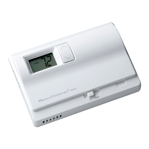
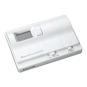
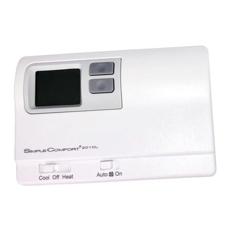
SC1001/SC1001V
Non-Programmable Electronic Thermostat
• ControlsSingleStageHeating/
CoolingSystems
• SingleStageHeatPump
Systems
• CompatiblewithGas,Oilor
ElectricSystems
• Easyslidebartemperature
adjustment
• Mercury-Free,Environmentally
Safe
Parts Diagrams (SC1001/SC1001V)
NOTES:
SC1001= horizontal orientation
SC1001V= verical orientation
Fan Switch
High Temperature
Switch
Freeze Switch
Non HP – HP
Jumper
Electric/Gas
Jumper
Mode Switch
RG O B Y W C
GAS
ELEC
NON
HP
HP
SC1001
Specifications
Input:
•Voltage: 18-30 VAC
Output:
•Maximum: 1 amp per terminal (3 amp total for all terminals)
•Temperaturecontrolranges:55°F to 90°F Accuracy: ± 1°F
•Differentialrange:Fixed 2°F
•Systemcongurations: Single-stage heat, single-stage cool or single-stage heat pump,
gas, oil, electric
•Terminations: R, W, Y, O, B, G, C
Important Safety Information
•Alwaysturnoffthethermostatbeforeinstalling,removing,cleaning,orservicing;turnoffthepower
atthemainpowersourcebyunscrewingfuseorswitchingoffcircuitbreaker
•Donotswitchto“Cool”ifroomtemperatureisbelow50°F;thiscoulddamageyourA/Csystemand
causeinjury
•Donotinstallonvoltageshigherthat30VAC
•Allwiringmustconformtolocalandnationalbuildingandelectricalcodesandordinances
•Whilecleaning,donotgetsoapdirectlyonthermostatswitchesorslidebararea;onlyuseadamp
cloth with a mild soap to wipe outside of thermostat cover
Specifications
Packageincludes: SimpleComfort®non-programmablethermostatonbase,thermostatcover,wiring
labels,screwsandwallanchors,Installation,OperationandApplicationGuide.
Toolsrequiredforinstallation:Drillwith3/16”bit,hammer,screwdriver.
General Description
• TheSimpleComfort®thermostat is a mercury-free, non-programmable, electronic thermostat
• Compatiblewithsingle-stageheating systems, heating/cooling systems, and heat pump
systems;workswithgas, oil, or electricsystems
• Compatibleasamaster thermostatinzonedsystemapplications
• Freeze Protection Feature:Protectspipesfromfreezing!Iftheroomtemperaturedropsto40°F,
thethermostatautomaticallyturnsontheheat;thethermostatmustbeintheHeatposition.
• Built-in Compressor Protection for Air Conditioners: To protect the A/C’s compressor, there is a
5-minutedelaybetweenthesystemturningoffandtheA/Cstarting
To Remove Existing Thermostat
ELECTRICALSHOCKHAZARD
–
Turn off power at the main service panel by removing
the fuse or switching the appropriate circuit breaker to the OFF position before
removing the existing thermostat.
1. Turnoffpowertotheheatingsystembyremovingthefuseorswitchingtheappropriatecircuit
breakeroff.
2. Removecoverofoldthermostat.Thisshouldexposethewires.
3. Labeltheexistingwireswiththeenclosedwirelabelsbeforeremovingwires.
4. Afterlabelingwires,removewiresfromwireterminals.
5. Removeexistingthermostatbasefromwall.
6. Refertothefollowingsectionforinstructionsonhowtoinstallthisthermostat.
To Install Thermostat
ELECTRICALSHOCKHAZARD
–Turnoffpoweratthemainservicepanelbyremoving
thefuseorswitchingtheappropriatecircuitbreakertotheOFFpositionbefore
removingtheexistingthermostat.
IMPORTANT: Thermostat installation must conform to local and national building and electrical
codes and ordinances.
Note:
Mountthethermostataboutvefeetabovetheoor.Donotmountthethermostaton
anoutsidewall,indirectsunlight,behindadoor,orinanareaaffectedbyaventor
duct.
1. Turnoffpowertotheheatingandcoolingsystembyremovingthefuseorswitchingoffthe
appropriatecircuitbreaker.MovetheCool/OFF/Heat switch to OFF
.
2. MovetheFANAUTO/ON switch to AUTO.
3. Toremovecover,insertandtwistacoinorscrewdriverintheslotsonthetopofthethermostat.For
SC1001Vmodels,slotsarelocatedontheleftside.
4. Putthermostatbaseagainstthewallwhereyouplantomountit(Besurewireswillfeedthrough
thewireopeninginthebaseofthethermostat).
5. Marktheplacementofthemountingholes.
6. Setthermostatbaseandcoverawayfromworkingarea.
7. Usinga3/16”drillbit,drillholesintheplacesyouhavemarkedformounting.
8. Useahammertotapsuppliedanchorsintomountingholes.
9. Alignthermostatbasewithmountingholesandfeedthecontrolwiresthroughwireopening.
10. Usesuppliedscrewstomountthermostatbasetowall.
CAUTION!
:
Besureexposedportionofwiresdoesnottouchotherwires.
11. Tightenscrewsonterminalblock.Gentlytugwiretobesureofproperconnection.Doublecheck
thateachwireisconnectedtotheproperterminal.
12. Setthegas/electricjumper to electric or gas/oil, and heat pump jumper to NON-HP or HP.
13. Replacecoveronthermostatbysnappingitinplace.
14. Turnonpowertothesystematthemainservicepanel.
Replacing Wiring Labels
Old New Type
F, G G Fancontrolrelay
O O Cool active reversing valve
B B Heat active reversing valve
Y,Y6 Y Cooling control
H,W,4 W
Heating control
C Transformer, common side
M,4,RH,RS,R R Transformer, hot side
C Y or C
IftheCterminalisthecoolingcontrol,connecttoYterminal;ifitis
the common side of the transformer, connect to C terminal
Replacetheoldlabelswiththeenclosednewlabels:
