i
Thank you for choosing this Icom product.
This product is designed and built with Icom’s state of the art
technology and craftsmanship. With proper care, this product
should provide you with years of trouble-free operation.
IMPORTANT
READ ALL INSTRUCTIONS carefully and completely
before using the product.
SAVE THIS INSTRUCTION MANUAL—This instruction
manual contains important operating instructions for the
RMK-5 and RMK-7.
Refer to the transceiver’s INSTRUCTIONS for details on the
basic operations.
EXPLICIT DEFINITIONS
WORD DEFINITION
CAUTION Equipment damage may occur.
NOTE
If disregarded, inconvenience only. No risk of
personal injury, re or electric shock.
Icom is not responsible for the destruction, damage to, or
performance of any Icom or non-Icom equipment, if the
malfunction is because of:
• Force majeure, including, but not limited to, res, earthquakes,
storms, oods, lightning, other natural disasters, disturbances,
riots, war, or radioactive contamination.
• The use of Icom products with any equipment that is not
manufactured or approved by Icom.
DISPOSAL
The crossed-out wheeled-bin symbol on your
product, literature, or packaging reminds you
that in the European Union, all electrical and
electronic products, batteries, and
accumulators (rechargeable batteries) must be
taken to designated collection locations at the
end of their working life. Do not dispose of
these products as unsorted municipal waste. Dispose of
them according to the laws in your area.
Icom, Icom Inc. and the Icom logo are registered trademarks of Icom
Incorporated (Japan) in Japan, the United States, the United Kingdom, Germany,
France, Spain, Russia, Australia, New Zealand, and/or other countries.
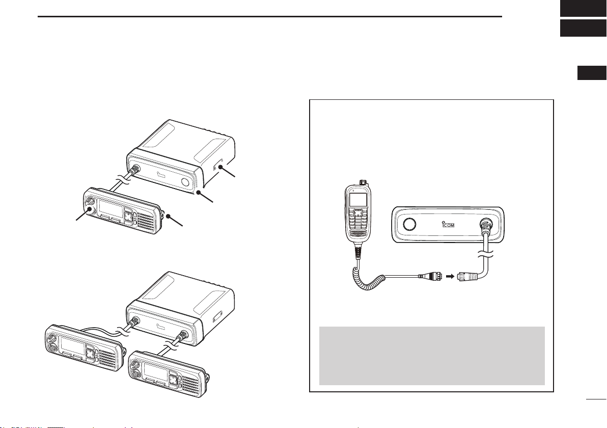
For the IC-F5400D and IC-F6400D series
To use the RMK-5 or RMK-7 with the IC-5400D and
IC-6400D series, the transceivers’ rmware revision must
be 1.6 or later.