Icom MA-500TR User manual

INSTRUCTION MANUAL
New2001
MA-500TR
CLASS B AIS TRANSPONDER
This device complies with Part 15 of the FCC
Rules. Operation is subject to the condition that
this device does not cause harmful interference.

New2001
i
FOREWORD
Thank you for purchasing this Icom product.
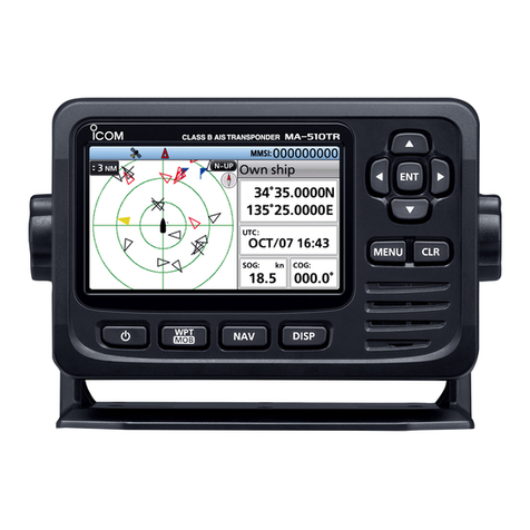
The MA-500TR c l a s s ba i s t r a n s p o n d e r is designed and
built with Icom’s state of the art technology and craftsman-
ship. With proper care, this product should provide you with
years of trouble-free operation.
We appreciate you making the MA-500TR your transpon-
der of choice, and hope you agree with Icom’s philosophy of
“technology first.” Many hours of research and development
went into the design of your MA-500TR.
DFEATURES
❍Full dot-matrix display visually shows real-time
vessel traffic information
❍IPX7 waterproof protection
❍3 lines of NMEA0183 Input/Output
❍GPS receiver comes with the MA-500TR
❍Collision-risk management functions
❍Integration with Icom VHF transceivers
*
*
See the leaflet that comes with the transponder for details of the
corresponding transceiver.
IMPORTANT
READ ALL INSTRUCTIONS carefully and completely
before using the transponder.
SAVE THIS INSTRUCTION MANUAL — This in-
struction manual contains important operating instructions
for the MA-500TR.
EXPLICIT DEFINITIONS
WORD DEFINITION
RWARNING! Personal injury, fire hazard or electric
shock may occur.
CAUTION Equipment damage may occur.
NOTE
If disregarded, inconvenience only. No risk
of personal injury, fire or electric shock.
CLEAN THE TRANSPONDER THOROUGHLY WITH
FRESH WATER after exposure to saltwater, otherwise, the
keys and switch may become inoperable due to salt crystal-
lization.

ii
New2001
FCC INFORMATION
• FOR CLASS A UNINTENTIONAL RADIATORS:
This equipment has been tested and found to comply with the
limits for a Class A digital device, pursuant to part 15 of the
FCC Rules. These limits are designed to provide reasonable
protection against harmful interference when the equipment
is operated in a commercial environment. This equipment
generates, uses, and can radiate radio frequency energy
and, if not installed and used in accordance with the instruc-
tion manual, may cause harmful interference to radio com-
munications.
Operation of this equipment in a residential area is likely to
cause harmful interference in which case the user will be re-
quired to correct the interference at his own expense.
SUPPLIED ACCESSORIES
Mounting bracket
For the mounting bracket
DC power cable (OPC-2059)
Knob bolts
Screws (5×20)
Flat washers
(M5)
Spring washers
(M5)
NMEA connector cable
(OPC-2014)
MXG-5000 g p s r e c e i v e r is included with MA-500TR.
MXG-5000 (Referred to as Internal GPS)
Cable length: Approx. 10 m (32.8 ft)
• An instruction sheet comes with the MXG-
5000. Please read it before installing and
operating the MXG-5000.
• The OPC-2014 has 15
leads, numbered 1 to 15.

iii
New2001
RADIO OPERATOR WARNING
WARNING
Icom requires the radio operator to meet the
FCC Requirements for Radio Frequency Expo-
sure. An omnidirectional antenna with gain not
greater than 9 dBi must be mounted a minimum
of 5 meters (measured from the lowest point of
the antenna) vertically above the main deck and
all possible personnel. This is the minimum safe separation
distance estimated to meet all RF exposure compliance re-
quirements. This 5 meter distance is based on the FCC Safe
Maximum Permissible Exposure (MPE) distance of 3 meters
added to the height of an adult (2 meters) and is appropriate
for all vessels.
For watercraft without suitable structures, the antenna must
be mounted so as to maintain a minimum of 1 meter vertically
between the antenna, (measured from the lowest point of the
antenna), to the heads of all persons AND all persons must
stay outside of the 3 meter MPE radius.
Do not transmit with radio and antenna when persons are
within the MPE radius of the antenna, unless such persons
(such as driver or radio operator) are shielded from antenna
field by a grounded metallic barrier. The MPE Radius is the
minimum distance from the antenna axis that person should
maintain in order to avoid RF exposure higher than the allow-
able MPE level set by FCC.
FAILURE TO OBSERVE THESE LIMITS MAY ALLOW
THOSE WITHIN THE MPE RADIUS TO EXPERIENCE RF
RADIATION ABSORPTION WHICH EXCEEDS THE FCC
MAXIMUM PERMISSIBLE EXPOSURE (MPE) LIMIT.
IT IS THE RESPONSIBILITY OF THE RADIO OPERATOR
TO ENSURE THAT THE MAXIMUM PERMISSIBLE EXPO-
SURE LIMITS ARE OBSERVED AT ALL TIMES DURING
RADIO TRANSMISSION. THE RADIO OPERATOR IS TO
ENSURE THAT NO BYSTANDERS COME WITHIN THE
RADIUS OF THE MAXIMUM PERMISSIBLE EXPOSURE
LIMITS.
Determining MPE Radius
THE MAXIMUM PERMISSIBLE EXPOSURE (MPE) RADIUS
HAS BEEN ESTIMATED TO BE A RADIUS OF ABOUT 3M
PER OET BULLETIN 65 OF THE FCC.
THIS ESTIMATE IS MADE ASSUMING THE MAXIMUM
POWER OF THE RADIO AND ANTENNAS WITH A MAXI-
MUM GAIN OF 9dBi ARE USED FOR AVESSEL MOUNTED
SYSTEM.

iv
New2001
1
2
3
4
5
6
7
8
9
10
11
12
13
14
15
16
Installation:
The installation of this equipment should be made in such a
manner as to respect the EC recommended electromagnetic
field exposure limits. (1999/519/EC)
The maximum RF power available from this device is 2 watts.
The antenna should be installed as high as possible for maxi-
mum efficiency and the installation height should be at least
0.4 meters above any accessible position. In the case where
an antenna cannot be installed at a reasonable height, then
the transmitter should neither be continuously operated for
long periods if any person is within a distance of 0.4 meters
of the antenna, nor operated at all if any person is touching
the antenna.
It is recommended that antenna of a maximum gain of 3 dB
are used. If higher gain antenna are required then please
contact your Icom distributor for revised installation recom-
mendations.
Operation:
The exposure to RF electromagnetic field is only applicable
when this device is transmitting. This exposure is naturally re-
duced due to the nature of alternating periods of receiving and
transmitting. Keep your transmissions to the minimum neces-
sary.
INSTALLATION NOTE

v
New2001
COUNTRY CODE LIST
• ISO 3166-1
Country Codes Country Codes
1
2
3
4
5
6
7
8
9
10
11
12
13
14
15
16
17
Austria
Belgium
Bulgaria
Croatia
Czech Republic
Cyprus
Denmark
Estonia
Finland
France
Germany
Greece
Hungary
Iceland
Ireland
Italy
Latvia
AT
BE
BG
HR
CZ
CY
DK
EE
FI
FR
DE
GR
HU
IS
IE
IT
LV
18
19
20
21
22
23
24
25
26
27
28
29
30
31
32
33
Liechtenstein
Lithuania
Luxembourg
Malta
Netherlands
Norway
Poland
Portugal
Romania
Slovakia
Slovenia
Spain
Sweden
Switzerland
Turkey
United Kingdom
LI
LT
LU
MT
NL
NO
PL
PT
RO
SK
SI
ES
SE
CH
TR
GB

vi
New2001
PRECAUTIONS
RWARNING! NEVER connect the transponder to an
AC outlet. This may pose a fire hazard or result in an electric
shock.
RWARNING! NEVER connect the transponder to a
power source of more than 16 V DC or use reverse polarity.
This could cause a fire or damage the transponder.
RWARNING! NEVER cut the DC power cable between
the DC plug at the back of the transponder and fuse holder. If
an incorrect connection is made after cutting, the transponder
may be damaged.
CAUTION:
NEVER place the
transponder
where normal
operation of the vessel may be hindered or where it could
cause bodily injury.
KEEP the transponder at least 1 m (3.3 ft) away from the
vessel’s magnetic navigation compass.
DO NOT use or place the transponder in areas with tem-
peratures below –20°C (–4°F) or above +60°C (+140°F) or, in
areas subject to direct sunlight, such as the dashboard.
DO NOT use harsh solvents such as benzine or alcohol
when cleaning, as they will damage the transponder surfaces.
If the transponder becomes dusty or dirty, wipe it clean with
a soft, dry cloth.
BE CAREFUL! The transponder rear panel will become
hot when operating continuously for long periods of time.
Place the transponder in a secure place to avoid inadvertent
use by children.
BE CAREFUL! The transponder meets IPX7* require-
ments for waterproof protection. However, once the tran-
sponder has been dropped, waterproof protection cannot be
guaranteed because of possible damage to the transponder’s
case or the waterproof seal.
* Except for the DC power and cloning cable connectors.
For U.S.A. only
CAUTION: Changes or modifications to this device, not
expressly approved by Icom Inc., could void your authority to
operate this device under FCC regulations.
Approved Icom optional equipment is designed for optimal
performance when used with an Icom transponder.
Icom is not responsible for the destruction or damage to an
Icom transponder in the event Icom transponder is used with
equipment that is not manufactured or approved by Icom.
Icom, Icom Inc. and the Icom logo are registered trademarks of Icom Incor-
porated (Japan) in Japan, the United States, the United Kingdom, Germany,
France, Spain, Russia and/or other countries.
MarineCommander is a trademark of Icom Incorporated.
All other products or brands are registered trademarks or trademarks of their
respective holders.

vii
New2001
TABLE OF CONTENTS
New2001
FOREWORD ......................................................................... i
IMPORTANT ......................................................................... i
EXPLICIT DEFINITIONS....................................................... i
FCC INFORMATION ............................................................ ii
SUPPLIED ACCESSORIES................................................. ii
RADIO OPERATOR WARNING.......................................... iii
INSTALLATION NOTE ........................................................ iv
COUNTRY CODE LIST........................................................ v
PRECAUTIONS................................................................... vi
TABLE OF CONTENTS ..................................................... vii
1 OVERVIEW......................................................................1
2 PANEL DESCRIPTION ...............................................2–6
■ Front panel ...................................................................2
■ Function display............................................................4
3 PREPARATION.........................................................7–13
■ MMSI code setting........................................................7
■ Initial setting mode .......................................................9
4 BASIC OPERATION ...............................................14–24
■ Turning power ON ......................................................14
■ Display backlight and contrast settings ......................15
■ Plotter display operation.............................................15
■ Target list display operation .......................................16
■ Danger list display operation......................................17
■ About the detail screen ..............................................17
■ Individual DSC call
(Possible only when a transceiver is connected)................24
5 OTHER FUNCTIONS ..............................................25–29
■ Message.....................................................................25
■ Waypoint ....................................................................26
■ Lost target ..................................................................29
6 MENU MODE OPERATION ....................................30–36
■ General ......................................................................30
■ Menu mode items.......................................................30
7 INSTALLATION AND CONNECTIONS ..................37–44
■ Connections ...............................................................37
■ Fuse replacement ......................................................40
■ About the VHF antenna..............................................40
■ Transceiver connection ..............................................41
■ Mounting the transponder ..........................................43
■ MB-75 installation.......................................................44
8 MAINTENANCE ......................................................45–47
■ Troubleshooting .........................................................45
■ Error message............................................................46
■ Diagnostics.................................................................46
9 SPECIFICATIONS AND OPTION .................................48
■ Specifications .............................................................48
■ Option.........................................................................48
10 TEMPLATE....................................................................49
11 AtoN CODE AND DESCRIPTION.................................51
1
DABOUT AIS
AIS is an acronym for “Automatic Identification System.”
An AIS transponder is a short range data radio unit, used
primarily for collision-risk management and navigation safety.
It automatically transmits and receives vessel information
such as the vessel name, MMSI code, vessel type, position
data, speed, course, destination and more. Information is ex-
changed among the vessels and/or base stations on the VHF
maritime mobile band. The information helps to identify other
nearby vessels or stations by displaying the received data on
a plotter or a radar screen.
Your vessel
(Class B AIS)
Other vessel
(Class A AIS)
Other vessel
(Class B AIS)
Base Station
Vessel information
DAIS Classes
There are seven types of AIS stations; vessels, base stations,
Aids to Navigation (AtoN), Search and Rescue (SAR), Search
and Rescue Transmitter (AIS-SART), MOB (Man OverBoard)
and EPIRB (Emergency Position Indicating Radio Beacon)-
AIS.
There are two classes of AIS units, which are installed on
vessels; Class A and Class B.
Under the Safety Of Life At Sea (SOLAS) convention, all
SOLAS vessels, as described below, are required to install a
Class A AIS transponder:
• Upwards of 300 gross tonnage engaged on international
voyages.
• Passenger vessels, irrespective of size, engaged on inter-
national voyages.
• Upwards of 500 gross tonnage not engaged on international
voyages.
A Class B AIS transponder is designed to be interoperability
with Class A units, but not to impact the Class A network.
Many commercial vessels, and some leisure craft, not clas-
sified as requiring a Class A unit, choose to install a Class B
unit to avoid accidents at sea.
1
1
OVERVIEW
New2001
1
2
3
4
5
6
7
8
9
10
11
12
13
14
15
16

2
New2001
PANEL DESCRIPTION
2
■Front panel
Function display (p. 4)
Speaker
qw e
r
w
e
t
y
io
u
The angle brackets show common or special display op-
erations, as described below:
• <Common> shows the common operation.
• <In the plotter display> shows the plotter display opera-
tion.
• <In the target list display> shows the target list display
operation.
• <In the danger list display> shows the danger list dis-
play operation.
qDISPLAY MODE KEY [DISP MODE]
<Common>
➥Push to switch the display mode between the plotter,
target list and danger list. (pp. 4−6)
➥While in the Menu mode, push to exit it, and return to
the plotter, target list or danger list display which was
selected before you entered the Menu mode.
wLEFT AND RIGHT KEYS [Ω]/[≈]
<Common>
While in the Menu item setting mode, push to select a
menu option. (pp. 31, 35)
<In the plotter display>
➥Push [Ω]to sequentially select each AIS target icon far-
thest from your vessel (or waypoint, if it is set; see page
26 for setting detail).
(p. 15)
➥Push [≈]to sequentially select each AIS target icon
closest to your vessel (or waypoint, if it is set; see page
26 for setting detail).
(p. 15)
•
A target box will appear around the selected target or waypoint
icon.
<In the danger list display>
➥Push [Ω]to sort the AIS target data by CPA (Closest
Point of Approach).
(p. 17)
➥Push [≈]to sort the AIS target data by TCPA (Time to
CPA).
(p. 17)

3
2
PANEL DESCRIPTION
New2001
eUP AND DOWN KEYS [∫]/[√]
<Common>
➥While in the Menu mode, push to select a menu item.
(pp. 9, 30)
➥Push to select a voice channel in the voice channel se-
lection screen.
(p. 24)
<In the plotter display>
Push to select the display range.
(p. 15)
<In the target or danger list display>
Push to select an AIS target in the target or danger list
display.
(pp. 16, 17)
rENTER KEY [ENT]
<Common>
➥Push to display the detail screen of the selected AIS
target. (pp. 15−17)
➥Push to save the input data. (pp. 8, 10, 15)
➥Push to enter the Menu item setting mode.
(pp. 9, 30)
➥While in the Menu item setting mode, push to select a
menu option.
(pp. 11, 12, 16, 31, 34
−36
)
➥While searching for a GPS satellite, push [ENT] to dis-
play the GPS information screen. (p. 14, 33)
tMENU KEY [MENU]
<Common>
➥Push to enter the Menu mode. (pp. 9, 30)
➥While in the Menu mode, push to exit it, and return to
the plotter, target list or danger list display which was
selected before you entered the Menu mode.
yCLEAR KEY [CLEAR]
<Common>
➥Push to cancel the entered function, or return to the pre-
vious screen. (pp. 10, 13, 25)
➥While in the Menu mode, push to exit it, and return to the
previous screen. (pp. 9, 30)
➥ Push to stop an alarm. (pp. 15−17)
uDSC KEY [DSC]
<Common>
➥When the AIS target is selected, or the detail screen is
displayed, push to display the voice channel selection
screen. (p. 24)
➥After selecting the voice channel, push to transmit an
Individual DSC call to the selected AIS target. (p. 24)
This function is available only when a transceiver is con-
nected to the transponder. (p. 41)
i POWER/BRILL KEY [POWER•BRILL]
<Common>
➥
Hold down for 1 second to turn the power ON or OFF.
(p. 14)
•
After turning ON the power, the opening screen will appear.
➥Push to show the display backlight and contrast adjust-
ing screen. (p. 15)
oMAN OVERBOAT KEY [MOB]
<Common>
Hold down for 1 second to set the waypoint.
(p. 27)
• The MOB alarm sounds, and a ag icon appears on your current
position.
2

4
2PANEL DESCRIPTION
New2001
■Function display
There are three display types; plotter, target list and danger list,
and you can select your desired type using the [DISP MODE] key.
NOTE: When one of the following messages is displayed on
the function display, push [CLEAR] to clear it.
• “PRIORITY INTERRUPTED LAST ATTEMPTS” is displayed
when the transponder cannot make a periodic transmission
because the transponder detects a transmit signal.
• “BASE STATION INHIBITING AIS TX FOR MM MIN”* is dis-
played when the transmission is inhibited by a base station
for the displayed time period.
*The transmission inhibit period is displayed instead of “MM.”
- “ ” is also displayed while transmission is inhibited.
DPlotter display
After the transponder is turned ON, the plotter display automati-
cally appears, if the GPS receiver is connected and it receives
signals from a satellite. It shows the display range and the icons
of the AIS targets.
r
y
t
q
e
w
u
i
qDISPLAY TYPE
Shows the selected display type.
• When “N-UP” is displayed, the top of the plotter display repre-
sents North.
• When “AC-UP” is displayed, the top of the plotter display repre-
sents the direction your course is heading.
wRANGE/CPA INFORMATION
➥Shows the range information from your vessel to the se-
lected AIS target.
➥Shows the CPA (Closest Point of Approach) information
of the selected AIS target whose CPA is within 6 nm
(nautical miles) and TCPA (Time to CPA) is within 60
minutes of your vessel.
eBEARING/TCPA INFORMATION
➥Shows the bearing information from your vessel to the
selected AIS target.
➥Shows TCPA information of the selected AIS target
whose CPA is within 6 nm (nautical miles) and TCPA is
within 60 minutes of your vessel.
rMESSAGE ICON
Appears when
a message is received.
•
The message icon stays on the plotter display as long as the
unread message is stored in the RX log memory.

5
2
PANEL DESCRIPTION
New2001
1
2
3
4
5
6
7
8
9
10
11
12
13
14
15
16
tTARGET BOX
Shows the selected AIS target (or waypoint, if it is set; see
pages 26–28 for setting detail).
• When a target box appears, push [ENT] to display the detail
screen of the selected AIS target or waypoint.
yYOUR VESSEL ICON
Your
vessel icon is displayed in the center of the display.
• When “N-UP” is displayed, the vessel icon automatically points
in the direction you are heading, in 45 degrees steps.
• When “AC-UP” is displayed, the vessel icon constantly points to
the top of the plotter display.
• When your vessel moves less than 2 knots, the icon is displayed
as “ .”
uKEY ENTRY GUIDE
Shows the key entry guide.
➥Push [Ω]or [≈]to select each AIS target icon (or way-
point), in sequence.
(p. 15)
•
A target box will appear around the selected target icon.
➥Push [ENT] to display the detail screen of the selected
AIS target or waypoint. (pp. 15–17)
iDISPLAY RANGE
Shows the selected display range.
• 0.125, 0.25, 0.5, 0.75, 1.5, 3, 6, 12, 24 nm (nautical miles) are
selectable.
• Description of the icons
Icon Description
AIS target: Vessel
The tip of the target triangle automatically points
in the direction it’s heading.
The icon blinks when the AIS target is closer than
your CPA and TCPA settings. (Dangerous target)
AIS target: Lost target*
The target triangle is marked with a diagonal line.
AIS target: Base Station
AIS target: Search and Rescue (SAR)
AIS target: Aids to Navigation (AtoN)
Waypoint
AIS target: AIS-SART, MOB and EPIRB-AIS
*A vessel is regarded as a “Lost target” after a specified pe-
riod of time has passed since the vessel last transmitted
data. (p. 29)
The “Lost target” icon disappears from the plotter display 6
minutes and 40 seconds after the vessel was regarded as a
“Lost target.” Ask your dealer for details.

6
2PANEL DESCRIPTION
New2001
■Function display (Continued)
DTarget list display
In the plotter display, push [DISP MODE] to switch to the tar-
get list display, which shows all AIS targets being detected by
the transponder.
The AIS target data is sorted by the distance from your ves-
sel, and the closest target is located on the top of the list.
e
q
w
qTHE NUMBER OF TARGETS
Shows the number of AIS targets which are being detected
by the transponder.
wKEY ENTRY GUIDE
Shows the key entry guide.
➥Push [∫]or [√]to select an AIS target.
(p. 16)
➥Push [ENT] to display the detail screen of the selected
AIS target. (pp. 16, 17)
eTARGET INFORMATION
Shows the following AIS target information:
• MMSI code or name, if the name is programmed.
• Range (RNG) from your vessel to the target (unit: nautical mile)
• Bearing (BRG) from your vessel to the target (unit: degree)
DDanger list display
In the target list display, push [DISP MODE] to switch to the
danger list display, which helps you to find any dangerous
target whose CPA is within 6 nm (nautical miles) and TCPA is
within 60 minutes of your vessel.
e
q
w
qTHE NUMBER OF DANGEROUS TARGETS
Shows the number of AIS targets which are being detected
by the transponder.
wKEY ENTRY GUIDE
Shows the key entry guide.
➥Push [Ω]or [≈]to sort the danger target data.
(p. 17)
➥Push [ENT] to display the detail screen of the selected
AIS target. (p. 17)
eDANGER TARGET INFORMATION
Shows the following dangerous target information:
• MMSI code or name, if the name is programmed.
• CPA : Closest Point of Approach (unit: nautical mile)
• TCPA: Time to CPA (unit: minute)
New2001

7
3
PREPARATION
New2001
1
2
3
4
5
6
7
8
9
10
11
12
13
14
15
16
■MMSI code setting
The 9-digit MMSI (Maritime Mobile Service Identity: DSC self
ID) code can be set at power ON. If the MMSI code has al-
ready been set, the following steps are not needed. Go to
page 9.
This initial code setting can be performed only once.
After being set, it can be changed by only your dealer or
distributor.
qHold down [POWER•BRILL] for 1 second to turn ON the
power.
• A long beep sounds, and the opening screen appears.
[POWER•BRILL]
wThe opening screen displays the results of the opening
test (ROM, RAM and backup data test); “OK” or “NG” (No
Good).
•
If “NG” is displayed, hold down [POWER•BRILL] for 1 second to turn
OFF the power, then ON again to reset the transponder. If there is no
change, contact your dealer or service center.
eAfter the opening test is completed, “No MMSI” appears
when no MMSI code is set.
• If the MMSI code has already been set, the MMSI code appears.
Go to page 9.
• Push [CLEAR] to skip the setting, and go to the plotter display.
In this case, the transponder operates as just an AIS receiver.
☞Continued on the next page.

8
3PREPARATION
New2001
■MMSI code setting (Continued)
r
Push [ENT] to enter the MMSI code setting mode.
tPush [∫]or [√]
to input
the specific 9-digit MMSI code.
• Push [≈]to move the cursor forward.
• Push [Ω]to move the cursor backward.
• Push [CLEAR] to cancel, and go to the plotter display. In this
case, the transponder operates as just an AIS receiver.
[CLEAR]
[ENT]
[∫], [√],
[Ω], [≈]
NOTE: The coast station ID or the group ID cannot be en-
tered as your MMSI code.
• Group ID : The rst one digit is “0.”
• Coast station ID : The rst two digits are “0.”
If you enter a code that starts with “0” or “00,” an error beep
sounds after pushing [ENT] in step y.
yAfter inputting the 9-digit code, push [ENT].
• The MMSI confirmation screen appears.
uInput the same MMSI code which was entered in steps t
and yfor the confirmation. Then, push [ENT] to save.
iAfter the MMSI code has been saved, the transponder au-
tomatically enters the Initial setting mode. See pages 9 to
13 for setting details.
The Initial setting mode can also be entered from the
Menu mode. (p. 9)

9
3
PREPARATION
New2001
1
2
3
4
5
6
7
8
9
10
11
12
13
14
15
16
■Initial setting mode
The Initial setting mode allows you to set the vessel’s infor-
mation that is exchanged among the vessels and/or base
stations. And, you can set the seldom-changed NMEA Input/
Output settings.
NOTE: After the MMSI code programming, the transpon-
der automatically enters the Initial setting mode. In this
case, skip steps qand w.
q Push [MENU] to enter the Menu mode.
wPush [∫]or [√]to select “Initial Setting,” then push [ENT].
e
Push [∫]or [√]to select the desired item, then push [ENT].
rEnter the characters or select the desired option.
The procedures are described on pages 10 to 13.
tRepeat steps eand rto set other items.
y Push [CLEAR] to exit the Initial setting mode, and return
to the Menu mode.
u Push [CLEAR] to exit the Menu mode.
[CLEAR]
[ENT]
[MENU]
[∫]
[√]
DMMSI code
Enter the vessel’s MMSI code.
See page 7 for setting details.
• If the MMSI code has already been set, you cannot change this.
DName
Enter the vessel’s name of up to 20 characters.
See page 13 for setting details.
DCall Sign
Enter the Call Sign of up to 7 characters.
The Call Sign is a unique designation ID for a station.
See page 13 for setting details.

10
3PREPARATION
New2001
■Initial setting mode (Continued)
DInternal/External GPS Antenna Position
Set these measurements to indicate the internal and/or exter-
nal GPS antenna position on the vessel.
• Internal GPS antenna : The GPS antenna which is connected to
the [GPS] connector.
• External GPS antenna :
The GPS antenna which is connected to one
of the NMEA lines. (p. 39)
q Push [∫]or [√]to select “A,” “B,” “C” or “D.”
• A : Bow to Antenna
• B : Stern to Antenna
• C : Port side to Antenna
• D : Starboard side to Antenna
• Push [CLEAR] to cancel and return to the previous screen.
w Push [Ω]or [≈]to input the value into that item.
A and B : Between 0 and 511 meters (0 and 1676.5 feet)
C and D: Between 0 and 63 meters (0 and 206.6 feet)
e Repeat steps qand wto input other values.
r Push [ENT] to save and return to the Initial setting mode.
[CLEAR]
[ENT]
[∫], [√],
[Ω], [≈]
To show the external GPS antenna set screen, select
“Set
EXT GPS POS” in the “Initial Setting” mode. (p. 9)
D Type of Ship
Select your vessel type.
➥P ush
[∫]or [√]
to select your vessel type from the list,
then push [ENT] to save and return to the Initial setting
mode.
[ENT]
[∫]
[√]
• Type of Ship List
30 Fishing 52 Tugs
31 Towing 53 Port tender
32 Towing & two < 200m 54 Vessels with anti pollution
33 Engaged in Dredging 55 Law enforcements Vessel
34 Engaged in Diving 58 Medical Transports
35 Engaged in Military 59 Ships RR Resolution NO18
36 Sailing 60 Passenger Ship
37 Pleasure Craft 70 Cargo Ship
50 Pilot 80 Tanker
51 Search & Rescue Vessel 90 Other Type
This screen shows the inter-
nal GPS antenna set screen.

11
3
PREPARATION
New2001
1
2
3
4
5
6
7
8
9
10
11
12
13
14
15
16
DNMEA Input/Output ports
• NMEA1/NMEA2/NMEA3 data speed
The data communication speed (baud rate) can be set for
each Input/Output port; NMEA1 and NMEA3.
NOTE: The data communication speed of NMEA2 is fixed
to 38400 bps. NMEA2 is used for communication between
the transponder and the Icom MarineCommander™ sys-
tem or a GPS receiver.
q P
ush [∫]or [√]to select “NMEA1” or “NMEA3.”
• NMEA1 : Used for communication between the transponder and
a transceiver or a GPS receiver. (Default: 4800 bps)
• NMEA3 : Used for communication between the transponder and
a navigational equipment or a GPS receiver.
(Default: 4800 bps)
• You cannot select “NMEA2.”
w Push [ENT] to select the data communication speed be-
tween 4800 bps and 38400 bps into that item.
• You can also select the option by pushing [Ω]or [≈].
e Repeat steps qand wto set another port.
r
Push [CLEAR] to save and return to the Initial setting mode.
[CLEAR]
[ENT]
[∫], [√],
[Ω], [≈]
• GPS Input1/GPS Input2/GPS Input3
Set the NMEA1, NMEA2 and NMEA3 Input ports’ capability.
q P
ush [∫]or [√]to select “GPS Input1,” “GPS Input2” or
“GPS Input3.”
•
“GPS Input1” is for the NMEA1, “GPS Input2” is for the NMEA2
and “GPS Input3” is for the NMEA3 ports setting.
w Push [ENT] to toggle this function ON or OFF.
• You can also turn the function ON by pushing [≈], or OFF by
pushing [Ω].
ON : The GPS information that is received from the ex-
ternal GPS receiver of the selected port is sent to
the transponder.
(Default for
“GPS Input2” and “GPS Input3”
)
OFF : The GPS information that is received from the ex-
ternal GPS receiver of the selected port is not sent
to the transponder. (Default for
“GPS Input1”
)
e Repeat steps qand wto set other ports’ capability.
rPush [CLEAR] to save and return to the Initial setting
mode.
[CLEAR]
[ENT]
[∫], [√],
[Ω], [≈]

12
3PREPARATION
New2001
■Initial setting mode
DNMEA Input/Output ports (Continued)
• AIS Output
Set the NMEA2 output port’s capability.
This function should normally be set to “
AIS
.”
q P
ush [∫]or [√]to select “AIS Output.”
w Push [ENT] to select either “AIS” or “AIS+GPS.”
• You can also select the option by pushing [Ω]or [≈].
AIS : The NMEA2 output port sends only the AIS
information to the connected device. (Default)
AIS+GPS : The NMEA2 output port sends both the AIS
and GPS information to the connected device.
This setting is recommended for use in an area
where there are few vessels. In areas crowded
with AIS equipped vessels, a large amount of
information is received. The output of GPS in-
formation has priority, so the NMEA2 output
port may not send some AIS information cor-
rectly. However, the transponder displays the
AIS information on it’s LCD correctly.
ePush [CLEAR] to save and return to the Initial setting
mode.
[CLEAR]
[ENT]
[∫], [√],
[Ω], [≈]
• Remote ID
Set a Remote ID number between 80 and 89.
The Remote ID is included in the sentence of the format for
the Icom own NMEA.
q P
ush [∫]or [√]to select “Remote ID
.
”
w Push [Ω]or [≈]to set a Remote ID number between 80
and 89.
ePush [CLEAR] to save and return to the Initial setting
mode.
[CLEAR]
[∫], [√],
[Ω], [≈]
Other manuals for MA-500TR
1
Table of contents
Other Icom Marine Radio manuals

Icom
Icom IC-M80 User manual

Icom
Icom IC-M802 Installation manual

Icom
Icom IC-M25 User manual

Icom
Icom IC-M802 Quick start guide

Icom
Icom IC-M802 Instruction Manual

Icom
Icom IC-M501 Quick start guide

Icom
Icom MarineComander MXS-5000 User manual

Icom
Icom MA-510TR User manual

Icom
Icom IC-M80 User manual

Icom
Icom MA-500TR User manual