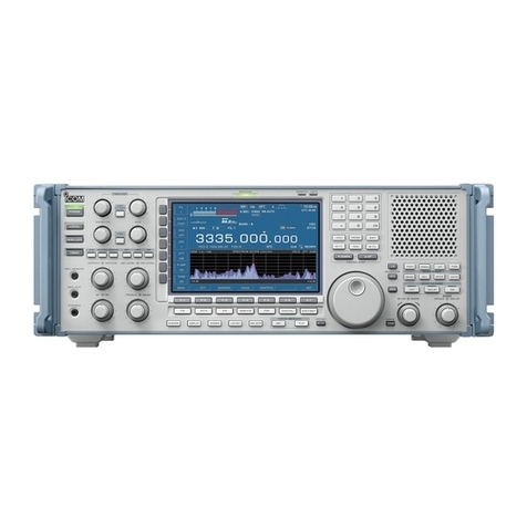
Icom IC-751A User manual

INSTRUCTION MANUAL
<x)iRgqgi

FOREWORD
Thank you very much for choosing this ICOM product.
The IC-751A HF transceiver is arefined version of the popular IC-751. Through intensive market
research, ICOM has compiled ideas from Amateur Radio operators worldwide and used this feedback in
an effort to design the best transceiver with those features actually required by today's active participant
In the field of Amateur communications. This research program is evidence of the basic ICOM philoso-
phy of providing aproduct Amateurs want.
This is it. The IC-751A is an all mode HF transceiver and general coverage receiver developed using the
most current computer-based design techniques and HF engineering.
Please study this instruction manual thoroughly to learn all functions of the IC-751A and refer back to
the manual periodically as necessary. Feel free to contact any authorized ICOM dealer should you have
questions regarding the operation or capabilities of the IC-751 A.
UNPACKING
1.DC power cable 1
2. Pin plugs 2
3. External speaker plug 1
4. Spare fuses (20 ampere) 2
5. Spare fuses (3 ampere) 2
6. CW key plug 1
7. Microphone (HM-36) 1

TABLE OF CONTENTS
SECTION 1FEATURES 1
SECTION 2SPECIFICATIONS 2
SECTION 3CONTROL FUNCTIONS 4
3-1 FRONT PANEL 4
3-2 FREQUENCY DISPLAY 12
3-3 TOP PANEL 12
3-
4REAR PANEL 13
SECTION 4INSTALLATION 15
4-
1PLANNING 15
4-2 MOUNTING THE TRANSCEIVER 15
4-3 ANTENNA 15
4-4 MICROPHONE 16
4-5 CW KEY 16
4-6 POWER SUPPLY 16
4-
7GROUND 17
SECTION 5SYSTEM INTERCONNECTIONS 18
5-1 AC POWER SUPPLY 18
5-2 EXTERNAL (LINEAR) AMPLIFIER 18
5-
3ANTENNA TUNER 19
5-4 RTTY TERMINAL UNIT 20
5-5 SSTV UNIT 21
5-
6ACCESSORY SOCKET CONNECTIONS 21
SECTION 6GENERAL OPERATION 22
6-
1SETTINGS 22
6-2 BASIC OPERATION 22
6-3 SSB OPERATION 25
6-4 CW OPERATION 26
6-5 AM OPERATION 27
6-6 FM OPERATION 28
6-7 RTTY OPERATION 29
6-
8GENERAL COVERAGE RECEIVER 30
SECTION 7FUNCTIONS OPERATION 32
7-
1VOX OPERATION 32
7-2 SPEECH COMPRESSOR OPERATION 32
7-3 NOISE BLANKER (NB) OPERATION 33
7-4 CW SEMI/FULL BREAK-IN OPERATION 33
7-5 SPLIT (DUPLEX) OPERATION 34
7-6 FM REPEATER OPERATION.. 34
7-7 PASSBAND TUNING (PBT) OPERATION 35
7-8 NOTCH FILTER OPERATION 36
7-9 FILTER SWITCH OPERATION 36
7-10 RIT/^ITX OPERATION 36
7-11 MONITOR OPERATION 38
7-12 MICROPHONE UP/DOWN OPERATION 39
7-13 AGC OPERATION 39
7-14 PREAMP/ATT SWITCH OPERATION 39

SECTION
SECTION
SECTION
SECTION
SECTION
SECTION
SECTION
SECTION
SECTION
8MEMORY AND SCANNING OPERATION 40
8-1 MEMORY CHANNEL SELECTION 40
8-2 PROGRAMMING MEMORY CHANNELS 40
8-3 MEMORY CLEARING 41
8-4 MEMORY SCAN 41
8-5 MODE SCAN 42
8-6 PROGRAMMED SCAN 42
8-
7SCAN RESUMPTION 42
9OTHER FUNCTIONS 43
9-
1VSWR READINGS 43
9-2 WWV/WWVH RECEPTION 43
10 OPTIONS INSTALLATION 44
10-1 FILTERS 44
10-2 IC-PS35 INTERNAL POWER SUPPLY 46
10-3 IC-EX310 VOICE SYNTHESIZER UNIT 47
10-4 CR-64 HIGH-STABILITY CRYSTAL UNIT 47
10-
5UT-30 PROGRAMMABLE ENCODER UNIT 48
11 CIRCUIT DESCRIPTION 49
11-
1RECEIVE CIRCUITS 49
11-2 TRANSMIT CIRCUITS 50
11 -3 PLL CIRCUITS 51
11-
4LOGIC CIRCUITS 52
12 MAINTENANCE AND ADJUSTMENTS 53
12-
1CLEANING 53
12-2 MAINTENANCE 53
12-
3ADJUSTMENTS 53
13 INSIDE VIEWS 55
13-
1TOP VIEVy 55
13-2 BOTTOM VIEW 56
13-3 RF UNIT 56
13-4 ADJUSTMENT LOCATIONS 57
14 BLOCK DIAGRAM .58
15 OPTIONS 59
16 SCHEMATIC DIAGRAM SEPARATE

SECTION 1FEATURES
COMPLETE HF RADIO
•ALL BAND, ALL MODE The IC-751A covers all Amateur HF frequencies from 1.8MHz to
ALL SOLID-STATE 30MHz, including the three new bands of 10MHz, 18MHz and
24MHz. It also offers SSB, CW, AM, FM and RTTY operating
modes as standard features. All circuits in the IC-751A, including
the driver and final power stages, are completely solid-state produc-
ing afinal output power of 100 watts.
The IC-751A features general coverage receive capability with a
tuning range from 100kHz to 30MHz. This wide range is accom-
plished by means of up-conversion using ahigh side IF and aCPU
control system.
For CW (Jperators, both semi break-in and full break-in are provided
for smooth, fast and natural CW conversations.
OUTSTANDING RECEIVER PERFORMANCE
•ICOM'S DFM SYSTEM The ICOM DFM (Direct Feed Mixer) feeds the incoming signals
directly into ahigh level first mixer developed by ICOM. This
advanced system produces ahigher spurious response rejection ratio,
ahigher receiver sensitivity and awider dynamic range.
•105dB DYNAMIC RANGE The IC-751 Ahas a105dB dynamic range. Even with the PREAMP
switched ON, the dynamic range is approximately lOOdB.
•PREAMP AND ATTENUATOR Both alOdB preamplifier PLUS a20dB attenuator are installed as
INCLUDED standard equipment. The preamplifier increases receiver sensitivity
while the attenuator provides added protection from intermodula-
tlon problems.
NEWLY DEVELOPED CPU
•VARIOUS SCANNING FUNCTIONS Memory Scan allows monitoring of all memory channels or only
those storing aparticular mode. Programmed Scan provides scan-
ning between any two programmed frequencies. Mode Scan auto-
matically monitors only memories containing frequencies with a
similar mode. In all cases, the Auto-stop function halts the scan
when asignal is received and the Resume function restarts the
scan when the frequency is clear.
•32 MEMORIES Thirty-two programmable memories are provided to store mode and
frequency, and the CPU is backed up by an internal lithium battery
to maintain the memories for up to ten years. Scanning of fre-
quencies or memories is possible from either the transceiver or the
HM-36 scanning microphone.
The IC-PS30 external AC power supply was developed especially for
ICOM base radios and matches the style and size of the IC-751 A.
This power supply uses arecently designed switching regulator,
resulting in light weight and high efficiency.
•IC-2KL The IC-2KL is acompletely solid-state, HF broadband linear am-
plifier with 500 watts output to give your signal the extra boost
needed for solid contacts when propagation is poor.
OPTIONS AVAILABLE
•IC-PS30
•GENERAL COVERAGE RECEIVER
•FULL BREAK-IN FUNCTION
-1-

SECTION 2SPECIFICATIONS
2-1 GENERAL
Number of semiconductors
Frequency coverage
Usable temperature range
Frequency control
Frequency readout
Frequency stability
Power supply requirements
Current drain (at 13.8V DC)
Antenna impedance
Weight
Dimensions
2-2TRANSMITTER
RF power
Emission modes
Harmonic emissions
Spurious emissions
Carrier suppression
Unwanted sideband
Microphone
ATX variable range
Transistors 59
(Australia, France: 61)
FETs 23
Diodes 336
ICs (Includes CPU) 64
Ham Bands
1.8MHz ~2.0MHz
3.45MHz- 4.1MHz
6.95MHz- 7.5MHz
9.95MHz- 10.5MHz
13.95MHz- 14.5MHz
17.95MHz- 18.5MHz
20.95MHz- 21.5MHz
24.45MHz -25.1MHz
27.95MHz -30.0MHz
General Coverage (Receive Only)
0.1MHz -30.0MHz
:-10°C--«-60°C (+14°F--M40°F)
:CPU based 10Hz step digital PLL synthesizer.
Independent transmit/receive frequency.
6digit 100Hz illuminated FIP.
Less than ±200Hz from 1to 60 minutes after power ON.
Less than ±30Hz after 1hour at 25° C.
Less than ±350Hz in the range of 0°C +50°C.
13.8V DC ±15% (negative ground), current drain 20A maximum at 200W input.
AC power supply is available for AC operation.
:Transmitting
At 200 watts input Approx. 20.0A
Receiving
At maximum audio output Approx. 1.8A
Squelched Approx. 1.5A
50 ohms unbalanced.
8.5kg
306(322)mm(W) X115(120)mm(H) x355(385)mm(D)
Bracketed values include projections.
SSB (J3E) :200 watts PEP input
CW (A1A) :200 watts input
FM (F3E) :200 watts input
RTTY (F1A) :200 watts input
AM (A3E) :50 watts output
SSB (J3E) Upper and Lower sideband
CW .(A1A)
FM (F3E)
RTTY (F1A)
AM (A3E)
More than 40dB below peak power output.
:More than 60dB below peak power output.
(Guaranteed for transmissions within the Amateur bands.)
:More than 40dB below peak power output.
More than 55dB down with 1000Hz AF input.
Impedance 600 ohms
Input level 12 millivolts typical
Dynamic or electret condenser
:±9.9kHz
-2-

2-3 RECEIVER
Receive system
Receive modes
Intermediate frequencies
Sensitivity
(PREAMP ON)
Squelch sensitivity
Selectivity
Spurious and image response rejection :
Audio output :
Notch filter attenuation :
RIT variable range :
SSB, CW, RTTY, AM
Quadruple-conversion superheterodyne with continuous bandwidth control.
FMTriple-conversion superheterodyne.
SSB (J3E) Upper and Lower sideband
CW (A1A)
FM (F3E)
RTTY (F1A)
AM (A3E)
1st: All modes 70.451 5MHz
2nd: SSB 9.0115MHz
CW, RTTY 9.0106MHz
FM, AM 9.0100MHz
3rd: All modes 455kHz
4th: SSB 9.0115MHz
CW, RTTY 9.0106MHz
AM 9.0100MHz
SSB, CW, RTTY
0.1 ~0.5MHz Less than 0.5/iV for lOdB S/N
0.5 ~1.6MHz Less than 1/iV for lOdB S/N
1.6
-30.0MHz Less than 0.15/iV for lOdB S/N
AM (NARROW FILTER selected)
0.1 ~0.5MHz Less than 3jLtV for lOdB S/N
0.5 ~1.6MHz Less than 6jLtV for lOdB S/N
1.6
~30.0MHz Less than IjuV for lOdB S/N
FM28 ~SOMHz Less than 0.3mV for 12d BSI NAD
1
.6
~SOMHz Less than 0.3/iV
SSB, CW, RTTY (WIDE FILTER selected), AM (NARROW)
2.3kHz at —6dB points
3.8kHz at -60dB points
CW, RTTY 500Hz at —6dB points
1.3kHz at —60dB points
FM 15kHz at —6dB points
30kHz at —50dB points
AM (WIDE FILTER selected) 8kHz at —6dB points
18kHz at —50dB points
Image rejection More than 80dB
IF rejection More than 70dB
More than 2.6 watts at 10% distortion with 8ohm load.
More than 45dB
±9.9kHz
-3-

SECTION CONTROL FUNCTIONS

©POWER SWITCH
ON OFF
This is apush-lock switch which controls the input DC power to
the IC-751A. When the IC-PS30 AC power supply is used, the
switch also acts as the AC power supply switch. Power is supplied to
the transceiver when the switch is pushed IN and locked. Power to
all circuits is cut (except to the PA unit when using aDC power
supply) when the switch is pushed again and released.
©AUTOMATIC GAIN CONTROL
SWITCH [AGC]AGC
©METER SWITCH
METER
COMP
©TRANSMIT/RECEIVE (T/R) SWITCH
TRANSMIT
RECEIVE
This switch changes the time constant of the AGC circuit. In the
SLOW position, the AGC voltage releases slowly for SSB reception.
In the FAST position, the AGC voltage releases quickly suitable for
receiving CW signals or signals with rapid fading.
In the OFF position, the AGC circuit and S-meter are disabled.
Also, the AGC circuit does not actuate in the FM mode.
In the transmit mode, the front panel meter has six functions.
Vc Indicates the collector voltage of the final transistors.
Ic Indicates the collector current of the final transistors.
COMP Indicates the compression level when the speech
compressor Is in use.
ALC Indicates the ALC level. The ALC circuit begins to
function when the RF output power reaches apreset
level.
Po Indicates the approximate output power.
SWR Indicates the SWR of the antenna system after the
meter is referenced at "SET" while the Po meter
function is selected.
This switch is for manually changing between transmit and receive.
Set the switch to RECEIVE (down) to place the IC-751A in the
receive mode. Move the switch to TRANSMIT (up) to change to
the transmit mode. When using the PTT SWITCH on the micro-
phone or VOX operation, the T/R SWITCH must be at RECEIVE.
)MIC CONNECTOR
©MIC INPUT
@+8V DC OUTPUT
©FREQ UP/DOWN
©PHONES JACK
Connect asuitable microphone to this connector. The supplied
HM-36 hand microphone or the optional SM-10 desk microphone
may be used. When using other microphones, refer to the diagram
in SECTION 4-4.
©AF OUTPUT
©GND (microphone ground)
©GND (PTT ground)
-(Dptt
(FRONT VIEW)
This jack accepts astandard 1/4 inch plug from headphones with
an impedance of 4~16 ohms. Stereo headphones may be used
without modification.
@AF GAIN CONTROL
AF GAIN RF GAIN
Increases the
audio level.
This control varies the audio output level in the receive mode.
Clockwise rotation increases the level.
-5-

d)RF GAIN CONTROL
SQUELCH -S>-TONE
Raises the
threshold level.
(0)TONE CONTROL
SQUELCH ^TONE
Treble
(Q)MIC GAIN CONTROL
MIC GAIN -®-RF PWR
®RF POWER CONTROL
MIC GAIN -^RF PWR
@FUNCTION SWITCH
This control varies the gain of the RF stage when the transceiver is
in the receive mode. Rotate the control fully clockwise for
maximum gain. When tuning in the SSB or CW mode, the S-meter
needle rises as the control Is rotated counterclockwise and only
those signals stronger than the level indicated by the needle are
heard.
This control sets the squelch threshold level. To turn OFF the
squelch function, rotate this control completely counterclockwise.
To set the threshold level higher, rotate the control clockwise.
Adjust this control clockwise until the green RECEIVE indicator
just goes out while no signal is being received.
This control varies the receive audio tone. Adjust the control to
provide the clearest, most pleasing audio.
Adjust this control for asuitable modulation level while speaking
into the microphone in anormal voice. Rotate the control clock-
wise to increase the gain.
This control varies the RF output power from 10 watts to
maximum.
•SSB :100W PEP
•CW, RTTY, FM :100W
•AM :BOW
Rotate the control clockwise to increase the output power. Use
the minimum power necessary for reliable communication.
This switch activates the secondary switch functions on the front
panel as indicated by the reverse-image lettering (white letters on
ablack background).
©FUNCTION INDICATOR
©MODE SWITCHES
am i™ CWPP3 SSB I3M RTTYlSna
The FUNCTION INDICATOR lights after the FUNCTION
SWITCH Is pushed, and indicates that the secondary switch func-
tions are activated.
AM:
Push for AM operation.
FM:
Push the FUNCTION SWITCH first, then push the AM SWITCH
to select the FM mode.
CW:
Push for CW operation with the standard filters.
-6-

®HAM BAND/GENERAL COVERAGE
SWITCH [HAM/GENEl
HAM/GENE SPEECH MODE-S SCAN
111111LJ
©SPEECH SWITCH
HAM/GENE SPEECH MODE-S SCAN
11111111
CW NARROW (NAR):
Push the FUNCTION SWITCH first, then push the CW SWITCH
for operation with the 455kHz narrow CW filter. There is no audio
output from the speaker if the optional filter is not installed.
SSB:
Push to automatically select upper sideband (USB) operation on
the 10MHz band and above, and lower sideband (LSB) operation
on the 7MHz band and below. In the GENERAL COVERAGE
mode, USB is selected from 9MHz upwards, and LSB is selected
below 9MHz.
SSB REVERSE:
Push the FUNCTION SWITCH first, then push the SSB SWITCH
to select LSB on the 10MHz band and above, and USB on the
7MHz band and below. In the GENERAL COVERAGE mode, LSB
Is selected from 9MHz upwards, and USB is selected below 9MHz.
RTTY:
Push for RTTY operation.
RTTY NARROW (NAR):
Push the FUNCTION SWITCH first, then push the RTTY SWITCH
for RTTY operation using the optional 455kHz narrow CW filter.
There is no audio output from the speaker if the optional filter is
not installed.
This switch changes the IC-751A between the Amateur Band and
General Coverage modes. In the Amateur Band mode, the trans-
ceiver functions on any of the HF amateur bands from 1.8 to
28MHz. In the General Coverage mode, the receiver functions on ail
frequencies from 0.1 to 30MHz. The IC-751A does not transmit
while in the General Coverage mode.
This switch activates the optional IC-EX310 speech synthesizer
which announces the displayed frequency in English.
®MODE SCAN SWITCH [MODE S]
HAM/GENE SPEECH MODE-S SCAN
oaaThis switch engages the selective mode function. Only memory
channels with the same operating mode as is displayed just prior to
pushing this switch are selected when the TUNING CONTROL or
the scan function is used. See SECTION 8for afull description of
the IC-751 Ascanning systems.
®SCAN START/STOP SWITCH [SCAN]
HAM/GENE SPEECH MODE-S SCAN
USB
/uzi Jnn,
//. CJLI. LI C, I
SCAN VFO A
—4
_
The “SCAN" indicator lights when any scan
function is activated.
®TUNING CONTROL Rotate this control clockwise to increase, or counterclockwise to
decrease the frequency or memory channel number. The frequency
actually changes in 10Hz steps in all operating modes at all times,
however, the tuning rate is 10Hz if the control is rotated slowly, but
jumps to 50Hz if the control is rotated more rapidly. This allows
both fine and coarse tuning of your operating frequency without
removing your hand from the TUNING CONTROL. Refer to the
TUNING SPEED SWITCH description below.
This switch starts and stops all scan functions. When the scan
restarts, it begins from the frequency on which the scan halted while
in the programmed scan mode, or from the highest memory channel
while in the memory mode. See SECTION 8for afull description of
the IC-751 Ascanning systems.
-7-

©DIAL LOCK This switch electronically locks the IC-751A on the currently dis-
played frequency and deactivates the TUNING CONTROL. This
function is useful while rag chewing or for mobile operation after
the IC-751 Ais set to the desired frequency. Disengage the dial lock
by pushing and releasing the switch.
Push this switch to increase the tuning rate to 1kHz while in any
operating mode. The 100Hz digit on the frequency display clears to
"0" simultaneously. Push and release the switch again to return to
the normal tuning, rate. Refer to TUNING CONTROL description
above.
(§)TS INDICATOR
(8)DIAL FUNCTION SELECT
SWITCH [DFSl
(g)DFS INDICATOR
@BAND SELECT SWITCH [BAND]
@BAND SELECT INDICATOR
(g) INCREMENTAL TUNING
CONTROL [RIT/^TXll
ATX
CL EZl
D
@NOTCH FILTER CONTROL
PBT-S)- NOTCH
NOTCH
Illuminates when the TS SWITCH function is activated.
While using the VFO mode, push this switch IN to lock the displayed
VFO operating frequency, and rotate the TUNING CONTROL to
change the displayed memory channel number.
While using the MEMORY CHANNEL mode, push this switch IN
to lock the displayed memory channel, and rotate the TUNING
CONTROL to change the displayed frequency.
Illuminates when the DFS SWITCH function is activated.
Push this switch and rotate the TUNING CONTROL In order to
change your band of operation. In the HAM BAND mode, the
IC-751 Ajumps to afactory set initialization frequency on each of
the amateur bands as the TUNING CONTROL is rotated. In the
GENERAL COVERAGE mode, the operating frequency is changed
in 1MHz steps.
Illuminates when the BAND SELECT function is activated.
This control shifts the receive or transmit frequency by up to
9.9kHz to either side of the frequency indicated on the main fre-
quency display. Refer to the RIT and idTX SWITCH descriptions
below.
Rotating this control clockwise (+ direction) raises the receive or
transmit frequency and counterclockwise (— direction) lowers the
frequency. The shifted amount and direction is indicated with
smaller numerals to the right of the main frequency display.
When both the RIT and idTX circuits are ON, both the receive and
transmit frequencies may be shifted together to either side of the
displayed frequency.
This control shifts the notch filter frequency when the NOTCH
SWITCH is ON. Adjust the control to minimize interference. Refer
to the description for the NOTCH SWITCH below and see SECTION
7-8for more information.
-8-

®PASSBAND TUNING CONTROL
PBT -g>- NOTCH
^^TX SWITCH
JTX
®RIT/zlTX CLEAR SWITCH
CL B1
This control allows continuous tuning of the receiver selectivity
when using the SSB, CW or RTTY mode. Besides reducing inter-
ference on the desired signal, PASSBAND TUNING may also
improve the receive audio. The normal position is in the center
(1 2o'clock) which sets filter bandwidth at 2.3kHz on SSB. Refer to
SECTION 7-7for more information.
This switch turns the variable receive frequency circuit ON and OFF.
When the circuit is activated, the letters "RIT" on the front panel
illuminate and the amount of shift is indicated. The amount and
direction of frequency shift is retained in memory whether the
circuit is ON or OFF until erased with the RIT/^TX CLEAR
SWITCH. Refer to the description for the INCREMENTAL TUN-
ING CONTROL and also SECTION 7-10 for more information.
This switch turns the variable transmit frequency circuit ON and
OFF. When the circuit is activated, the letters “AIX” on the front
panel illuminate and the amount of shift is indicated. The amount
and direction of frequency shift is retained in memory whether the
circuit is ON or OFF until erased with the RIT/idTX CLEAR
SWITCH. Refer to the description for the INCREMENTAL TUN-
ING CONTROL and also SECTION 7-10 for more information.
This switch clears the memory which contains the frequency shift
information as set with the INCREMENTAL TUNING CONTROL
and resets the small incremental tuning display to "0.0".
Push the FUNCTION SWITCH first, then this switch in order to add
the shifted frequency as shown on the incremental tuning display to
the frequency on the main frequency display. The incremental
tuning display resets to "0.0". Refer to SECTION 7-10 for more
information.
©FILTER SWITCH
FILTER
©NOTCH FILTER SWITCH
NOTCH
I
@VFO A/B SWITCH [A/Bl
This switch selects adifferent combination of the second IF (9MHz)
filter and the third IF (455kHz) filter to vary the overall selectivity
as shown in the following chart.
FILTER
SWITCH SSB CW/RTTY CW/RTTY
NARROW AM FM
OUT 2.3kHz 500Hz 500/250HZ 8kHz 15kHz
IN 2.6kHz 2.3kHz 500/250HZ 3kHz 15kHz
Refer to SECTION 7-9for more information.
This switch controls the notch filter circuit.
•Notch Filter OFF: Switch OUT
•Notch Filter ON: Switch IN
This switch selects either VFO Aor VFO Bfor tuning purposes.
©VFO EQUALIZING SWITCH [A=B] This switch instantly matches the frequency and mode of operation
of the two VFOs. The display does not change when this switch is
Pj|
pushed, however confirmation of the equalizing process is possible
^1by pushing the A/B SWITCH to check the frequency and mode of
the opposite VFO.
VFO A
VFO B
USB
VFO A
VFO A
,K
USB
/uJ/nn,
ILL 1U. LI LI 1
VFO A
USB
p1. 3S0.0 01
VFO B
1^
VFO B
Push A=B SWITCH.
USB
/uJ7nnr, ,
ILL 1U. LI 01
VFO B
-9-

®SPLIT (DUPLEX) SWITCH
®VFO/MEMORY SWITCH [VFO/Ml
[VFO/M]
This switch determines whether one VFO is used for both transmit-
ting and receiving, or whether both VFO Aand VFO Bare used.
•Single VFO operation :SPLIT SWITCH OUT.
•Dual VFO operation SPLIT SWITCH IN.
Refer to SECTION 7-5for more information.
This switch selects either the VFO or MEMORY CHANNEL mode
for tuning purposes.
USB
/ij zi ~i nn
ILL 1LI. un1
LI 1
USB
1LI JDn n
11. CJLI. LI
MEMO
n(
LI 1
VFQ A Push VFO/M SWITCH. -
©MEMORY WRITE SWITCH [WRITE]
©FREQUENCY TRANSFER SWITCH
[M VFO]
This switch stores the displayed operating frequency and mode
information in the memory channel indicated on the frequency
display. Memory writing is possible in either the VFO or MEMORY
CHANNEL mode. Refer to SECTION 8-2for information on pro-
gramming the memory channels.
This switch operates differently depending on which mode the
IC-751 Ais in.
•In the VFO mode, the frequency and mode stored in the memory
channel displayed transfer to the selected VFO.
•In the MEMORY CHANNEL mode, the displayed frequency and
mode transfer to the VFO used immediately prior to changing to
the MEMORY CHANNEL mode.
NOTE: When in the MEMORY CHANNEL mode, it is the
displayed frequency which transfers to the VFO. This is
not necessarily the MEMORY CHANNEL frequency
since the TUNING CONTROL and DFS SWITCH may
have been used to shift the operating frequency. Infor-
mation stored in the memory channel remains un-
changed after using the MVFO function.
VFO A
MEMO
CH-01
USB
IH.P3 0.S
SPT VFO «
VFO A
K
7ri ‘i 7n
1. LI J1. ULI 1
VFO A
I>
CW MMO
7n7n
1. U_/ 1. LI LI 1
Push the M^ VFO MEMO
SWITCH. CH-01
CW MEMO
1ncin n1
1. LI -/ /. LI u1
©FREQUENCY DISPLAY Refer to SECTION 3-2for adescription of the frequency display.
©TRANSMIT INDICATOR This indicator illuminates when the IC-751 Ais in the transmit mode.
©RECEIVE INDICATOR This indicator illuminates when the IC-751 AIs in the receive mode.
©NARROW FILTER INDICATOR This indicator illuminates when the narrow CW or RTTY filter is
selected. If the filter is not installed, the indicator still lights when
the narrow positions are selected, however the audio output is
muted.
-10 -

©MULTIFUNCTION METER In the receive mode, the IC-751A front panel meter acts as an
S-meter (signal strength meter). In the transmit mode, the meter
has six different functions as stated in Item (3) METER SWITCH.
©NOISE BLANKER TIMING SWITCH
[NB WIDE]
The blanking time of the noise blanker circuit may be set for
NORMAL or WIDE with this switch. Use this switch in conjunction
with the NOISE BLANKER LEVEL CONTROL described in Item
©SPEECH COMPRESSOR SWITCH
[COMP] .
This switch turns the RF speech compressor circuit ON and OFF.
The circuit provides greater talk power by improving the intelligi-
bility of the transmitted signal over long distances.
©VOX SWITCH This switch turns the VOX circuit ON and OFF. The automatic
T/R switching VOX circuit functions in the PHONE and CW modes
when the switch is IN. In CW, semi break-in or full break-in opera-
tion is possible.
•SEMI BREAK-IN,
FULL BREAK-IN OPERATION Semi break-in operation refers to automatic switching of the
transceiver between the transmit and receive modes in unison
with the operator's speech or the closing and opening of the CW
telegraph key.
Full break-in operation, usable only with CW, is the same except
the transceiver switches even more rapidly after each element of
an individual letter is sent. Full break-in operation closely
simulates full duplex communication.
©VOX GAIN CONTROL
GAIN—vox—DELAY
Increases
keying speed
KEY SPEED
This control increases and decreases the sensitivity of the VOX
circuit. When operating in the CW mode, iambic keyer operation is
possible.
•When operating in the SSB, AM or FM mode, adjust the control so
the VOX circuit activates with anormal speech level.
•When operating in the CW mode, this control turns the electronic
keyer unit ON and OFF, plus varies the speed (5-45 wpm) of the
unit. When the control is OFF, manual CW operation is possible.
©VOX DELAY CONTROL
(VOX time constant)
This control changes the transmit to receive switching time. Adjust
it so transmit to receive switching occurs during pauses in your
speech or CW transmission.
©NOISE BLANKER LEVEL CONTROL
[NB LEVEL] NB WIDE
NB LEVEL
OFF
This control varies the threshold level of the noise blanker. Adjust
to remove the noise without adding distortion to the received signal.
-11 -

3-2 FREQUENCY DISPLAY
FM AM CW USB
-I UJ
II. L
LSB c
IJ.
.GENE SPT, lSCANmVFOA VFO
RTTY
/
I
ij
1rRIT ^TX'
-oo
J. J
'MEMO
‘
J J
JL
®MODE INDICATOR This area of the display shows the operating mode currently selected.
The modes available are FM, AM, CW, USB, LSB or RTTY.
(g)GENERAL COVERAGE INDICATOR "GENE" lights when the IC-751A is in general coverage mode.
When "GENE" is not lit, the transceiver is in the HAM BAND mode.
(g) FREQUENCY READOUT This readout shows the operating frequency using 6digits and
100Hz resolution.
@SPLIT INDICATOR
(g)SCAN INDICATOR
g)VFO INDICATOR
©MEMORY INDICATOR
©SHIFT FREQUENCY INDICATOR
"SPT" lights when separate VFOs are used for the transmit and
receive frequencies. This allows operation with atransmit frequency
which is different from the receive frequency. When "SPT" is not
illuminated, asingle VFO is used for both transmit and receive.
"SCAN" lights whenever ascan function is selected.
"VFO A" or "VFO B" lights to indicate which VFO is currently
selected.
"MEMO" lights when the memory mode is selected. The selected
memory channel number from 01 to 32 is also shown.
"RIT" or "^TX" lights when the receive or transmit incremental
tuning function is activated, respectively. The direction and
quantity of the shift is also shown. Both functions may be activated
simultaneously if desired. Refer to SECTION 7-10 for more infor-
mation.
-12 -

®PREAMP/ATT (Attenuator) SWITCH
(§)MONITOR/MARKER SWITCH
(§)MARKER CALIBRATOR
(0MONITOR LEVEL CONTROL
(§)ANTI-VOX CONTROL
This switch selects the RF preamplifier to amplify weak receive
signals or the RF attenuator to prevent overloading of the receiver.
Refer to SECTION 7-14 for more Information.
This switch turns the MONITOR or MARKER circuit ON or OFF,
•Vary the monitor level with the MONITOR LEVEL CONTROL.
•Acalibration marker is generated every 10kHz when the circuit is
activated.
This control varies the marker frequency. Use an accurate standard _
frequency source such as radio station WWV/WWVH to calibrate the
marker generator. See SECTION 12-3 (2) for more information.
This control changes the audio level of the CW sidetone or SSB
monitor circuit when the MONITOR SWITCH on the top panel is
turned ON. Adjust the control for the desired monitor volume.
When using the VOX function, sound from the speaker may cause
unwanted switching of the T/R relay. Adjust this control in con-
junction with the VOX GAIN CONTROL so the T/R relay switches
only from the operator's voice and not from the speaker audio.
3-4 REAR PANEL
©
#
@ANTENNA CONNECTOR Connect a50 ohm impedance antenna to this connector. The con-
nector mates with aPL-259 plug.
®T/R CONTROL JACK [RELAY]
(§) EXTERNAL ALC JACK [ALC]
(§) RECEIVE ANTENNA OUTPUT
[RECEIVE ANT OUT]
An output signal from this jack controls the transmit/receive switch-
ing of an external amplifier or transverter.
NOTE: DO NOT attempt to switch greater than 50 volts, 0.5
ampere.
This jack accepts an automatic level control signal from an external
amplifier or transverter. The ALC voltage must be in the range of
0volts to —4 volts.
The receive signals from the ANTENNA CONNECTOR pass through
the transmit/receive antenna switching circuit to this jack. Normally,
the receiver IN and OUT jacks are connected together with ajumper.
The ANTENNA OUTPUT JACK is useful when operating with a
separate receiver or an external preamplifier.
-13 -

(§) RECEIVER INPUT [RECEIVE ANT INl This is an input jack which connects to the receiver RF stage.
©TRANSVERTER JACK [X-VERTER]
©SPARE JACK
©GROUND TERMINAL
©KEY JACK
©EXTERNAL SPEAKER JACK
©ACCESSORY SOCKET
©DC POWER SOCKET [DC 13.8V]
©IC-EX309 (OPTIONAL) INTERFACE
UNIT CONNECTOR POSITION
ANT
Connect asuitable transverter to this jack for operation on VHF/
UHF frequencies. The output is approximately 30mV.
This jack is not used. It may be useful for connecting apersonal
accessory.
To prevent electrical shocks, TVI, BCI and other problems, be
sure to ground the equipment through the GROUND TER-
MINAL. For best results, use the heaviest gauge wire or strap
available and make the connection as short as possible.
For CW operation, connect aCW key using the supplied standard
1/4 inch, 3-conductor plug. The terminal voltage from external
electronic keyers must be less than 0.4 volts DC.
When using the IC-751A internal iambic keyer, connect an iambic
keyer paddle using the supplied 1/4 inch, 3-conductor plug. See
SECTION 4-5and 6-4for more information.
Connect an external speaker to this jack, if required. Use aspeaker
with an impedance of 4~16 ohms and remember the built-in
speaker does not function when using the EXTERNAL SPEAKER
JACK.
This socket provides signals such as T/R switching, receiver output,
modulation output, etc. Refer to SECTION 5-6for more informa-
tion.
Connect the DC power cable from the IC-PS35 internal power
supply, the IC-PS30 or IC-PS15 external power supply or other
suitable supply. Refer to SECTION 4-6for more information.
This position is for the installation of the DP-25 connector from the
optional IC-EX309 interface unit.
@1C-PS35 (OPTIONAL) AC POWER
SUPPLY SOCKET POSITION
This position is for the installation of the AC power socket when
the optional IC-PS35 internal power supply is used.
-14 -

SECTION 4INSTALLATION
4-1PLANNING Select alocation for your transceiver which allows free access to the
front panel controls, good air circulation and rear clearance for
access to the rear panel connections.
•PRECAUTIONS
4-2 MOUNTING THE TRANSCEIVER
4-3 ANTENNA
•Mobile or marine installations:
An optional IC-MB18 mounting bracket is available to mount your
IC-751A. Select alocation which can support the weight of the
unit, and which does not interfere with the normal operation of
the vehicle or boat. Provide protection from direct rain on boats. “
Avoid using the IC-751 Ain the following situations:
1) Where temperatures under —10°C or over +60°C are encountered.
For example, DO NOT use the IC-751 Ain areas exposed to direct
sunlight or near heat-producing devices such as heaters or ranges.
2) In humid or moist places including bathrooms.
DO NOT run the antenna feedline near electronic instruments or
magnetic compasses.
The optonal IC-MB18 mounting bracket allows installation of the
transceiver ta asurface over the IC-751 A. When mounting the
transceiver aboard aboat, place the bracket in alocation which
minimizes vibration and wave shock.
Antennas play avery important role in radio communication. If
the antenna is inferior, your transceiver cannot give you the best
performance. Awell-matched 50 ohm antenna and feedline will
provide the desired performance.
Since the IC-751 Acomes standard with ageneral coverage receiver,
it is recommended that along wire antenna and antenna tuner be
used when receiving outside the Amateur bands. The tuner will
ensure there is amatched condition at all times. An Amateur band
antenna generally does not give adequate performance when used on
frequencies for which it was not designed.
•MOBILE ANTENNA
NOTE: To install the AH-2, an OPC-137 inter-
face cable must be purchased separately.
The ICOM AH-2 Antenna System may be bumper-mounted, plus it
offers automatic band switching and tuning in unison with the
IC:751A.
-15 -

4-4 MICROPHONE The supplied HM-36 electret condenser hand microphone or
optional SM-8 or SM-10 desk microphone may be used. Merely plug
it into the MICROPHONE CONNECTOR on the front panel. If you
wish to use adifferent microphone, make certain it has the proper
output level. Particular care must be exercised when wiring a
different microphone since the transceiver internal electrical switch-
ing system is dependent upon the correct connections. See
SECTION 3-1FRONT PANEL Item ®for MIC CONNECTOR
connections.
4-5 CW KEY For CW operation, connect aCW key to the KEY JACK using the
supplied standard 1/4 inch, 3-conductor plug. See the diagrams for
connection details.
Note that the keyed voltage when switching with semiconductors or
relays with resistors in the circuit must be less that 0.4 volts.
4-6POWER SUPPLY When an AC power supply is required, the IC-PS35 internal power
supply, or the IC-PS30 or IC-PS15 external power supply with
matching size and style is recommended.
CAUTION: Voltages greater than 15 volts DC may damage this
transceiver. Check the source voltage before con-
necting the power cable when using with non-ICOM
AC power supplies.
•AC OPERATION WITH THE IC-PS30
-16 -
Other manuals for IC-751A
2
Table of contents
Other Icom Receiver manuals

Icom
Icom IC-RX7 User manual

Icom
Icom IC-R8600 User manual

Icom
Icom IC-R71A User manual

Icom
Icom IC-R1 User manual

Icom
Icom IC-R5 User manual

Icom
Icom mxa- 5000 User manual

Icom
Icom IC-R9500 User manual

Icom
Icom IC-R8600 User manual

Icom
Icom COMMUNICATION RECEIVER IC PCR100 User manual

Icom
Icom IC-R30 User manual