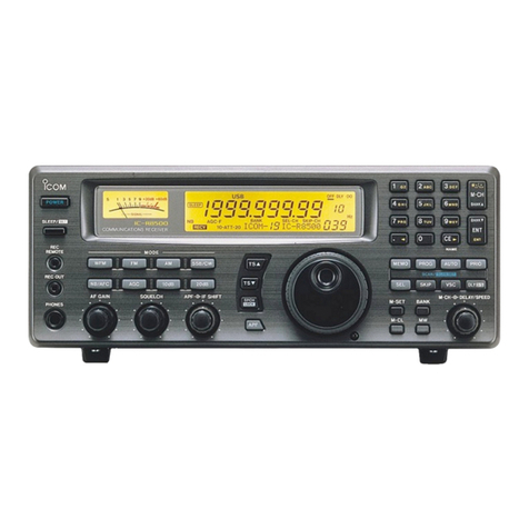
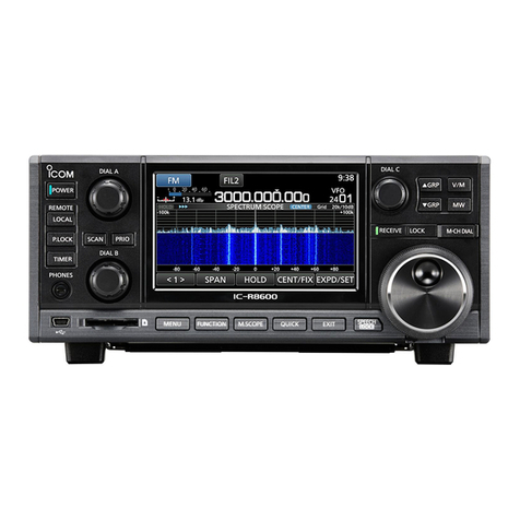
Icom IC-RSOOCOL User manual

fe)
ICOM
INSTRUCTION
MANUAL
COMMUNICATIONS
RECEIVER
IC—RSOOCOL
Icom
Inc.

INTRODUCTION
Thank
you
for
choosing
this
new
Icom
product.
The
IC-RSOOOL
is
an
advanced
communications
receiver
designed
for
professional,
worldwide
communications.
Equipped
with
Icom’s
state-of-the-art
LCD
monitor,
the
IC-R9OOOL
includes
an
advanced
multi-functional
scanning
system,
a
spectrum
scope
and
an
excellent
stability
oscilla-
tor
that
give
you
sophisticated
measuring
capability.
IMPORTANT
(1)
READ
THIS
INSTRUCTION
MANUAL
CAREFULLY
before
attempting
operation.
If
you
have
any
ques-
tions
regarding
the
operation
of
the
IC-R9OOOL,
feel
free
to
contact
your
nearest
authorized
Icom
Dealer
or
Service
Center.
(2)
SAVE
THIS
INSTRUCTION
MANUAL
—
This
instruc-
tion
manual
contains
important
safety
and
operating
instructions
for
the
|C-R9OOOL.
PRECAUTIONS
(1)
NEVER
let
metal,
wire
or
other
objects
touch
any
internal
part
of
the
receiver.
Risk
of
electrical
shock
could
occur.
(2)
NEVER
place
the
receiver
within
the
reach
of
children
or
babies
at
any
time.
(3)
NEVER
expose
the
receiver
to
rain,
snow
or
any
liquid,
(4)
DO
NOT
operate
the
receiver
when
it
is
covered
by
objects
which
impede
heat
dispersal.
{5)
AVOID
using
the
receiver
in
temperatures
below
—10°C
(+14°F)
or
over
+50°C
(+122°F).
The
receiver
may
not
function
properly
in
extreme
temperatures.
(6
AVOID
placing
the
receiver
in
excessively
dusty
environments
and
in
direct
sunlight.
(7
BE
CAREFUL!
The
heatsink
may
become
hot
when
operating
the
receiver
continuously
for
long
periods.
(8)
Unplug
the
AC
power
cable
from
the
AC
outlet
and
wait
a
few
minutes
when
opening
the
receiver
cover.
EXPLICIT
DEFINITIONS
The
following
explicit
definitions
apply
to
this
instruction
manual.
Personal
injury,
fire
hazard
or
electric
shock
may
occur.
Equipment
damage
may
occur.
\f
disregarded,
inconvenience
only.
No
personal
injury,
risk
of
fire
or
electric
shock.
8
aaahons
}
J
iy
as
Tint
Oe
Accessories
included
with
the
1C-R9000:
Qty.
@D
ACpowercable.....
62
ce ee
ee
ee
eee
eee
1
(2
Rack
mounting
handles
.......
3
Screws
(for
rack
mounting
handles)
@
Rearstands
......
®
Screws
(for
rear
stands)
.
©
DIN
plugs
(&pin).
..
.
D
Pin
plugs
(RCA
plugs)
.
oe
®
Connectioncable.....-..+
weeeee
@
Spare
fuses
(2
A
for
fuseholder)......
(4
A
for
internal
regulator).
.
.
.
(0.5
A
for
ACC
socket).
.....
Mini
plugs...
...
se
eee
eee
eee
ee
ee
eee

TABLE
OF
CONTENTS
3
INTRO
QUG
TION
sw
nessavsiccaroue
nvsceimynnieniie
i
EAE
INT
a
sstin
cance
ainad
cctoimckan
atanene
i
PRECAUTIONS
iia
asses
catia
neti
i
EXPLICIT
DEFINITIONS.............
i
UNPACKING!
saci
sarwis
ain
away
arias
i
TABLE
OF
CONTENTS..............
ii
FEATURES
(cos
siace
tc
rmacamans
1~2
CONTROL
FUNCTIONS...........
3~10
2-1
FRONT
PANEL
wae
&
2-2
REAR
PANEL
wcus.
ose
ion
ave
oa
FT
2-3
LCD
MONITOR
9
2-4
HATCH
COVER
10
CRT
DISPLAY
SCREEN
MENU...
11
~
23
3-
1
SCREEN
MENU
CONSTRUCTION
...
11
So
2)
MENU
TSCREENL
«
sna
camae
cay
14
323!
MENU
2:SCREEN«
wees
sonics
-.
14
3-
4
SCAN
CONDITION
SCREENS
......
15
3-
5
MEMORY
LIST
SCREEN..........
16
3-
6
MEMORY
EDIT
SCREEN..........
17
3-
7
MEMORY
NOTE
WRITE
SCREEN...
17
3-
8
SPECTRUM
SCOPE
SCREEN
18
3-
9
CLOCK
&
TIMER
SCREEN.
-.
18
3-10
SLEEP
TIMER
SCREEN.......
2:3
12
3-11
DAILY TIMER
SET
(1)
SCREEN....
19
3-12
DAILY
TIMER
SET
(2)
SCREEN....
20
3-13
CLOCK
ADJUSTMENT
(1)
SCREEN..
20
3-14
CLOCK
ADJUSTMENT
(2)
SCREEN..
21
3-15
TERMINAL
MONITOR
SCREEN.....
21
3-16
DATA
FORMAT
SCREEN
,. wn
Be
3-17
ClI-V
CONDITION
SCREEN
...
a3
22
3-18
FSK
MODE
SELECT
SCREEN
.
«2
23
3-19
BANK
STATUS
SCREEN..........
23
HANDLES
AND
STANDS
a3
CONNECTIONS............0.05.
FARRER
AR
NOOBRWN
SYSTEM
INTERCONNECTIONS
...27~
31
5-1
TAPE
RECORDER
CONNECTIONS...
27
5-2
MONITOR
DISPLAY
CONNECTION..
28
5-3
FSK
TERMINAL
UNIT...........
29
5-4
ACCESSORY
SOCKET
INFORMATION......,-.+-000205
30
5-5
REMOTE
JACK
INFORMATION.
...
.
31
6
10
11
12
13
14
15
BASIC
OPERATION.............
32
~
36
6-1
INITIAL
SETTINGS......
32
6-2
FREQUENCY
SETTINGS....
-
33
6-3
RECEIVING
z
avirescsussase
crcowny
wave
e
35
FUNCTIONS
RECEIVING
...
PAY
TSHR.
comes
waee
as
7-2.
NOTCH
FILTER............004-
7-3
AUTOMATIC
GAIN
CONTROL
TG
snc
ecicccaieus
spinvdeectansnaes
eats
38
7-4
NOISE
BLANKER.............-.
38
MEMORY
CHANNELS...........
39
~
40
8-1
MEMORY
CHANNEL
SELECTION...
39
8-2
MEMORY
WRITING
...,.........
4
8-3
SELECTED
MEMORY
NUMBER.
42
8-4
MEMORY
NOTE...........-
.
42
8-5
MEMORY
CLEARING...
43
8-6
MEMORY
EDITOR
FUNCTION
.....
44
SCANNING
sscicce
cs
arsvemsinsairageswncs
45
~54
9-1
PRE-OPERATION............005-
45
9-2
PROGRAMMED
SCAN....
47
9-3
PRIORITY
SCAN.......
49
9-4
AF
SCAN......-....5.
50
9-5
MEMORY
SCAN................
51
9-6
SELECTED
MODE
MEMORY
SCAN..
52
9-7
SELECTED
NUMBER
MEMORY
SSDI
eins
saul
sr
bideerecevnani
oirenaeiete
53
9-8
AUTO
MEMORY
WRITE
SCAN.....
54
CLOCK
AND
TIMER
OPERATION
.......0cseeeeeeues
55
~
58
10-1
CLOCK
ADJUSTMENT............
55
10-2
SLEEP
TIMER............0.000.
56
10+@)
(DAVEY
TIMBRE:
2
was
a
nace.
4
cieass
57
MAINTENANCE
ti<4
te
11-3
11-4
COVER
REMOVAL...
.
61
11-5
FUSE
REPLACEMENT...
iri:
Ge
A138
*GRUMRESETTING?
weg
acre:
sawn
ae
63
ADSUSTMENT
as
sssisos
ss
srsis
a
ecetew
eras
64
~
65
12-1
FREQUENCY
CALIBRATION.......
64
12-2
MAIN
DIAL
BRAKE
ADJUSTMENT..
64
12-3
OPTIONAL
VOICE
SYNTHESIZER
UNIT)
«cnn
e
cove
once
65
PRESIDE
WIENS
os
ite
estan
aceon
siescs
an
66
SPECIFICATIONS
0.
csi
eceine
sates
nau
67
m1)
FEATURES
FULL,
CONTINUOUS
100
kHz
~
1999.8
MHz
COVERAGE
WITH
ALL
MODES
MULTI-FUNCTIONAL
LCD
MONITOR
1000
MEMORY
CHANNELS
STORING
REQUIRED
FREQUENCIES
SUPER-HIGH
FREQUENCY
STABILITY
The
IC-R9OOOL
is
an
all-mode,
super
wide-band
receiver
that
continuously
covers
a
frequency
range
of
100
KHz
to
1999.8
MHz.
Many
parts
of
the
world
are
now
accessible.
Tune
in
world
news
agencies
that
use
FAX
and
RTTY,
aircraft,
marine
and
business
contacts,
emergency
services,
government,
satellite,
amateur,
CB
(Citizen's
Band)
and
numerous
other
stations
near
your
home
or
on
the
other
side
of
the
world.
Some
versions
do
not
cover
the
entire
range.
lcom’s
advanced
multi-functional
LCD
monitor
is
built
into
the
IC-R9OOOL.
Receive
frequencies,
modes,
and
additional
useful
data
are
displayed
for
your
operating
convenience.
The
LCD
monitor
has
the
following
outstanding
features:
eSPECTRUM
SCOPE
FOR
VISUAL
SIGNAL
CON-
FIRMATION
At
a
glance,
you
can
check
relative
signal
strengths
of
nearby
receive
frequencies.
The
span
of
the
spectrum
scope
can
be
selected
for
+25,
+50
or
+100
kHz
according
to
your
needs,
MEMORY
LIST
Using
the
memory
list
screen,
you
can
see
the
contents
of
10
memory
channels
at
once.
Memory
channels
can
be
rolled
for
viewing
other
memory
channels.
e
TERMINAL
MONITOR
This
screen
allows
you
to
monitor
RTTY
or
packet
radio
on
the
LCD
monitor.
ASCII(RS-232C
level)
code
date
from
RTTY
terminal
unit
or
TNC
(Terminal
Node
Con-
troller)
can
be
monitored.
A
total
of
1000
memory
channels
store
frequencies,
mode,
filter
width
and
tuning
step
increments.
1000
memory
channels
are
grouped
in
10
memory
banks
(each
100-digit
channel
numbers).
You
can
use
different
memory
banks
according
to
station
type,
frequency
ranges,
or
whatever
your
preference.
By
using
the
memory
list
screen,
many
more
convenient
functions
are
provided:
up
to
8
character
notes
for
your
reference;
the
advanced,
super
convenient
memory
editor
function
easily
moves,
copies
and
deletes
the
memory
contents.
Another
Icom
achievement
is
the
IC-R9OOOL's
very
high
frequency
stability
in
the
difficult-to-manage
GHz
range.
Frequency
stability
is
+0.25
ppm”
in
ranges
greater
than
30
MHz
and
+25
Hz"
in
ranges
less
than
30
MHz.
*0°C
~
+50°C;
+32°F
~
+122°F

MULTI-SCAN
FUNCTIONS
SCANNING
PAUSE,
TIMER
AND
VSC
(Voice
Scan
Control)
ADDITIONAL
OUTSTANDING
FEATURES
FEATURES
1
The
IC-R9000L
has
7
different
scan
functions.
\t's
the
perfect
system
for
searching
for
desired
signals
quickly.
The
scan
speed
is
adjustable
to
suit
your
needs,
and
its
speed
is
unbelievably
fast
—
13
channels/sec
or
more,
PROGRAMMED
SCAN
Scans
between
pre-programmed
scan
edges.
MEMORY
SCAN
Scans
memory
channels.
SELECTED
NUMBER
MEMORY
SCAN
Scans
memory
channels
with
the
same
programmed
selected
number.
SELECTED
MODE
MEMORY
SCAN
Scans
memory
channels
with
the
same
programmed
mode.
PRIORITY
SCAN
Monitors
specified
memory
channels.
AF
SCAN
Scans
around
the
receiving
frequency.
AUTO
MEMORY
WRITE
SCAN
Programs
receive
frequencies
into
memory
channels
during
programmed
scan.
The
IC-R9OOOL
provides
versatile
scan
resume
functions
when
a
signal
is
received:
the
scan
cancels,
pauses
until
a
signal
disappears,
pauses
for
adjustable
time,
and
pauses
for
the
mixed
condition
of
‘‘signal
disappears”
and
“adjustable
time.”
Also,
a
newly
developed
audio
detecting
VSC
system
allows
you
to
skip
inconvenient
signals
such
as
signals
with
no
modulation,
beat
signals,
and
noise
component
signals.
*A
wide
variety
of
tuning
steps.
10
Hz,
100
Hz,
1
kHz,
5
kHz,
9
kHz,
10
kHz,
12.5
kHz,
20
kHz,
25
kHz
and
100
kHz
available.
Automatic
dial
click
functions
when
more
than
5
kHz
tuning
steps
are
selected.
Built-in
ODS
(Direct
Digital
Synthesizer)
for
high-speed
scanning
with
a
high
C/N
(Carrier-to-Noise)
ratio.
excellent
sensitivity
for
all
frequency
coverages
with
a
high
dynamic
range
of
103.5
dB*.
*
On
14
MHz
band,
CW
mode,
filter
narrow.
©
Dual
clock,
2
kinds
of
sleep
timers
and
5
indpendent
daily
timers.
*eAn
advanced
AFC
(Auto
Frequency
Control)
for
auto-
matic
tuning
of
the
center
frequency
of
the
receive
signal.
*A
threshold-adjustable,
width-selectable
noise
blanker.
Advanced
interference
rejection
circuits,
IF
shift
and
notch
filter.
Recording
control
through
a
tape
recorder
with
optional
frequency
recording.
CI-V
control
system,
Rack
mounting
handles
for
mounting
with
a
19-inch
rack.

—p
2
qa
-1
FRONT
PANEL
RF
GAIN
NB
LEVEL
@
a3
a)
)
POWER
SWITCH
[POWER]
Turns
ON
and
OFF
main
power.
2
TIMER
SWITCH
[TIMER]
(p.
56)
Activates
a
timer
function.
:
&-
:
Alarm
timer
or
OFF.
fmm:
Sleep
timer
or
daily
timer.
(3)
METER
SWITCH
(p,
36)
Selects
a
meter
function.
s
§
:
Signal
strength
meter.
mm.
Center
meter
(activates
in
FM
or
WFM).
4)
MULTI-FUNCTION
METER
(p.
36)
@
oe
2
Shows
the
relative
signal
strength
or
signal
deviation.
See
(33
METER
SWITCHES
for
selection.
AGC
SWITCHES
(p.
38)
Select
the
AGC
time
constant,
slow,
fast
and
OFF.
)
AF
GAIN
CONTROL
[AF
GAIN]
Adjusts
audio
output
level,
)
SQUELCH
CONTROL
[SQUELCH]
(p.
35)
Adjusts
squelch
threshold
level.
When
[RF
GAIN]
squelch
may
open
except
in
FM
or
WFM
mode.
SQUELCH
9...
Loose
‘®
BASS
RESPONSE
CONTROL
[BASS]
Adjusts
the
bass
response
of
the
audio
output.
CONTROL
FUNCTIONS
BAlis
——
TONE
—
TRE)ILE
is
rotated
counterclockwise
the
ic)
(0
®
iE)
@
18)
(9
20)
ad
a
2
TREBLE
RESPONSE
CONTROL
[TREBLE]
Adjusts
the
treble
response
of
the
audio
output.
NOISE
BLANKER
SWITCH
[NB]
(p.
38)
Activates
the
noise
blanker
circuit.
Use
together
with
(NB
LEVEL].
Noise
blanker
deactivates
in
FM
and
WFM
modes.
NOISE
BLANKER
WIDTH
SWITCH
[NAR/WIDE]
(p,
38)
Removes
wide-type
pulse
noise
known
as
“woodpecker."”
©
Turn
ON
[NB]
to
use
this
switch.
@
LED
goes
out
Narrow
selected
LED
lights
up
Wide
selected
NOISE
BLANKER
LEVEL
CONTROL
[NB
LEVEL]
(p.
38)
Adjusts
the
noise
blanker
threshold
level.
noise
without
signal
distortion,
¢
Turn
ON
[NB]
to
use
this
control.
Suppresses
RF
GAIN
CONTROL
[RF
GAIN]
(p.
35)
Adjusts
gain
at
the
RF
stage.
©The
S-meter
needle
rises
when
the
control
is
rotated
counterclockwise.
Only
those
signals
stronger
than
the
level
indicated
by
the
needle
will
be
heard.
SCAN
SPEED
CONTROL
[SPEED]
(pgs.
48
~
54)
Adjusts
the
scanning
speed,
SCAN
DELAY
TIME
CONTROL
[DELAY
TIME]
(p.
46)
Adjusts
the
time
delay
between
“‘scan
stop’’
and
‘‘scan
resume.”
Select
scan
resume
switches
[A]
or
[B]
to
use
this
control.
te
Zamiont
nec
|reccn
pifwen
Mel
eR
|
Tw

3
A
a
A
Z|]
(8
VOICE
SCAN
CONTROL
SWITCH
[VSC]
(p.
46}
Restarts
a
scan
after
a
few
seconds
when
it
stops
on
a
signal
without
voice
or
audio
signals.
(®
SCAN
RESUME
SWITCHES
(p.
46)
Select
the
scan
resume
condition.
———,
Scanning
does
not
resume
while
a
signal
is
{OFF]|
being
received.
Scanning
resumes
approx.
3
sec.
after
a
signal
disappears.
Resumes
scanning
several
seconds*
after
scanning
stops.
Scanning
stops
for
several
seconds”
even
if
the
signal
disappears.
{al
Resumes
scanning
several
seconds”
after
{Bl
scanning
stops.
Scanning
resumes
approx.
3
sec”
after
the
signal
disappears.
{eo}
|
Cancels
a
scan
when
a
signal
is
received.
L
*
Time
can
be
adjusted
with
the
[DELAY
TIME]
control.
(®
HEADPHONES
JACK
[PHONES]
Accepts
4
~
16
&
mono
or
stereo
headphones
with
a
standard
1/4
inch
plug.
‘9
RECORDING
JACK
[REC]
(p.
27)
Audio
output
jack
for
a
tape
recorder.
The
fixed
audio
output
level
is
set
for
a
tape
recorder
AUX
jack.
eRefer
to
p.
65
Section
12-3
for
voice
synthesizer
information.
@
CALIBRATOR
POT
AND
SWITCH
[CALIBRATOR]
(p.
64)
The
calibrator
pot
adjusts
the
reference
oscillator
frequency.
Use
a
screw
driver
to
adjust.
The
calibrator
switch
generates
calibration
markers
every
500
kHz
up
to
29.500
MHz.
CONTROL
FUNCTIONS
2
2)
RECORDER
SPEECH
SWITCH
[REC
SPEECH]
(p.
65)
Announces
the
frequency
through
the
[REC],
[LINE
OUT]
and
[SPEECH
OUT]
jacks
when
scan
stops.
©
An
optional
UT-36
VOICE
SYNTHESIZER
UNIT
is
needed
for
this
function.
Refer
to
p.
65
Section
12-3
for
[REC
SPEECH]
and
[LINE
MIX]
combination.
@®
DIMMER
SWITCH
[DIMMER]
Dims
the
intensity
of
the
LCD
monitor,
function
meter,
and
all
indicators
on
the
front
panel.
2
BRIGHT
CONTROLS
[METER],
[LCD]
Adjust
the
following
intensities.
[METER]
:
Meter
and
indicators
(LCD]
:
LCD
monitor
(Set
to
the
2
o’clockposition)
NOTE:
Great
intensity
will
shorten
the
life
of
the
Tr.
Bright
2
TIMER
INDICATOR
[TIMER]
(p.
56)
Indicates
the
[TIMER]
switch
is
ON.
‘)
RECEIVE
INDICATOR
[RECEIVE]
Indicates
the
squelch
is
open.
2%
CALIBRATOR
INDICATOR
[CALIBRATOR]
(p.
64)
Indicates
the
[CALIBRATOR]
switch
is
ON.
@
RECORDER
SPEECH
INDICATOR
[REC
SPH]
(p.
65)
Indicates
the
[REC
SPEECH]
switch
is
ON.

2
CONTROL
FUNCTIONS
@®
LOCK
INDICATOR
[LOCK]
(p.
10)
Indicates
the
[LOCK]
switch
is
ON.
(
LCD
MULTI-FUNCTION
SWITCHES
[F-1]
~
[F-6]
(pgs.
11
~
23)
Select
LCD
monitor
menu
functions.
30
SCAN
SWITCHES
Starts
and
stops
priority
scan,
|
[PROG]
|
Starts
and
stops
programmed
scan.
|
(p.
47)
|
[Af]
|
Starts
and
stops
AF
scan.
(p.
50)
(MoD
Starts
and
stops
selected
mode
memory
scan.
(p.
52)
If
V
10}
|
Starts
and
stops
memory
scan.
(p.
51)
[SEL]
Starts
and
stops
selected
number
|
(p.
53)
memory
scan.
[AUTO
Starts
and
stops
auto
memory
write
scan.
Gl)
Cl-V
REMOTE
RESET
SWITCH
[REMOTE]
(p.
31)
The
indicator
above
the
switch
lights
up
when
one
of
the
following
Cl-V
remote
commands
is
received
through
the
[REMOTE]
jack
on
the
rear
panel:
-
AF
gain
controlling
data
-
RF
gain
controlling
data
-
Squelch
level
controlling
data
(p.
54)
The
switch
resets
the
above
commands
and
respects
the
individual
controls.
(2)
ATTENUATOR
SWITCHES
(p.
35)
Select
10
dB,
20
dB
or
30
dB RF
attenuation
to
prevent
front
end
overload.
To
select
30
dB
attenuation,
push
both
[ATT
10dB]
and
[ATT
20dB].
o
@
@
@
&)
DISPLAY
SWITCH
[DISPLAY]
Sets
the
LCD
monitor
to
an
external
video
input
@)
ANTENNA
SELECTOR
SWITCH
[ANTENNA]
(p.
26)
Allows output
of
13.8
V
DC
(max.
100
mA)
from
the
rear
panel
[ANT
SEL]
jack.
Use
an
external
antenna
selector,
preamplifier,
etc.,
with
this
voltage.
This
switch
can
be
used
with
the
rear
panel
[HF
ANT
SW]
when
operating
below
30
MHz.
See
p.
7
©
(HF
ANT
SW)
for
more
details.
)
AUTO
FREQUENCY
CONTROL
SWITCH
[AFC]
(p.
35)
Turns
ON
and
OFF
the
AFC
function.
«
Activates
in
FM
or
WFM
mode.
3%
MODE
SWITCHES
(p.
36)
Select
the
operating
mode.
©
WFM
mode
cannot
be
selected
below
30
MHz.
G)
KEYBOARD
(p.
33)
Sets
the
operating
frequency
or
memory
channel.
Selects
a
scan
group
during
programmed
scan,
auto
memory
write
scan
or
selected
number
memory
scan.
Enter
the
operating
frequency
or
memory
channel
number,
Sets
a
MHz
digit.
Clears
entered
digits
during
frequency
input.
Sets
the
memory
channel
using
the
entered
number.
Sets
the
operating
frequency
using
the
entered
frequency.

S
(ey
Ss
©
&
TUNING
STEP
SWITCHES
[SLOW]
/[FAST)
|p.
34)
Select
the
main
dial
step
increments
in
10
Hz,
100
Hz,
1
kHz,
5
kHz,
9
kHz,
10
kHz,
12.5
kHz,
20
kHz,
25
kHz
or
100
kHz
steps.
)
¢
co)
SPEECH
SWITCH
[SPEECH]
(p.
65)
Announces
the
operating
frequency
with
a
synthesized
voice.
#An
optional
UT-36
VOICE
SYNTHESIZER
UNIT
is
needed
for
operation.
MAIN
DIAL
(p.
34)
Sets
the
operating
frequency;
changes
programmed
contents
on
the
function
screen.
LOCK
SWITCH
[LOCK])
(p.
10)
Deactivates
the
main
dial
and
some
other
switches.
Switch
function
is
selected
by
internal
[LOCK]
switch
located
under
the
hatch
cover.
)
FILTER
WIDTH
SWITCHES
(p.
36)
Set
the
IF
filter
to
a
wide,
middle
or
narrow
width.
ln
WFM
mode,
filter
width
is
fixed
even
if
the
switches
are
changed.
«In
FM
mode,
[WIDE]
cannot
be
selected
below
30
MHz.
wie
MIDDLE
NARROW
ao
0
)
NOTCH
SWITCH
[NOTCH]
(p.
37)
Activates
the
notch
filter
circuit.
Use
together
with
the
[NOTCH]
control.
©
No
effect
in
FM
and
WFM
modes.
eS
c)
@
a
CONTROL
FUNCTIONS
2
\F
SHIFT
CONTROL
[IF
SHIFT)
(p.37)
Electronically
shifts
the
IF
frequency
to
reduce
inter-
ference
from
adjacent
frequency
signals.
NOTCH
CONTROL
[NOTCH]
(p.
37)
Adjusts
the
notch
filter
frequency
to
remove
a
beat
signal.
«Push
the
[NOTCH]
switch
to
use
this
control.
§
MEMORY
BANK
SWITCHES
[DOWN]
/[UP]
(p.
39)
Change
memory
channels
up
or
down
in
100
channel
steps.
MEMORY
WRITE
SWITCH
[WRITE]
(p.
41)
Stores
the
displayed
contents
(frequency,
mode,
filter
width
and
tuning
step)
into
the
selected
memary
channel.
Push
and
hold
this
switch
to
write
a
memory.
}
MEMORY
CHANNEL
SELECTOR
[DN
UP]
(p.
39)
Selects
a
memory
channel.
MEMORY
CLEAR
SWITCH
[CLEAR]
(p.
43)
Clears
the
contents
from
the
selected
memory
channel.
®
To
clear
the
memory,
push
and
hold
this
switch.
MHz
UP/DOWN
SWITCHES
[DOWN]
/[UP]
(p.
34)
Change
the
operating
frequency
in
1
MHz
steps.

J
2
CONTROL
FUNCTIONS
2-2
REAR
PANEL
()
DC-DC
POWER
SOCKET
Accepts
a
regulated
13.5
~
15
V
DC
input.
This
socket
does
not
accept
voltage
from
a
non-regulated
power
source
such
as
a
vehicle’s
battery.
©
Some
versions
do
not
have
this
socket.
2)
30
MHz
~
1000
MHz
ANTENNA
CONNECTOR
(p.
26)
Connects
a
50
82
30
~
1000
MHz
antenna
with
a
type-N
connector.
This
connector
is
automatically
selected
when
operating
in
30
~
1000
MHz,
(3)
1000
MHz
~
2000
MHz
ANTENNA
CONNECTOR
(p.
26)
Connects
a
50
&2
1
~
2
GHz
antenna
with
a
type-N
connector.
This
connector
is
automatically
selected
when
operating
in
1000
~
1999
MHz,
4)
GROUND
TERMINAL
[GND]
(p.
26)
Connect
this
terminal
to
ground
using
the
heaviest
gauge
wire
or
strap
available,
and
make
the
connection
as
short
as
possible.
(5)
HF
ANT
1
CONNECTOR
[HF
ANT
1]
(p.
26)
Connects
a
50
2.
HF
antenna
with
a
PL-259
connector.
This
connector
is
used
when
operating
below
30
MHz.
See
6)
[HF
ANT
SW].
6)
HF
ANTENNA
SWITCH
[HF
ANT
SW]
Selects
connections
at
[HF
ANT
1]
or
[HF
ANT
2]
when
operating
below
30
MHz.
|
SWITCH
PosiTiON
—|
raed
ian]
ea
|
cM
(Front
panel
ee
HF
ANT
1
ANT!
[on
[ar
ant
HE
ANT
2
[on
[HF
ant
1
)
ANTENNA
SELECTOR
VOLTAGE
OUTPUT
JACK
[ANT
SEL]
(p.
26)
Outputs
13.8
V
DC
(max.
100
mA)
when
the
[ANTENNA]
switch
on
the
front
panel
is
ON.
Use
for
an
external
preamplifier
or
antenna
selector,
if
desired.
ANT
2
i
8)
HF
ANTENNA
2
JACK
[HF
ANT
2]
(p.
26)
Connects
a
high
impedance
HF
antenna
such
as
a
long
wire
antenna
with
an
RCA
jack
(400
~
500
{2).
This
connector
is
used
when
operating
below
30
MHz.
See
®
[HF
ANT
SW]
above.
(
SPARE
JACK
[SPARE]
No
connection.
10
IF
OUTPUT
JACK
[IF
OUT]
Outputs
a
10.7
MHz
IF
signal.
Output
level
is
the
same
level
as
an
antenna
input
signal
or
below
(when
the
AGC
function
is
activated
or
the
attenuator
is
ON.)

)
ACC
SOCKET
[ACC]
(p.
30)
Input
and
output
connections
for
an
external
terminal
unit
for
use
with
data
communications
such
as
RTTY,
FAX,
etc.
‘(2
DATA
INPUT
SOCKET
[DATA
IN]
(p.
30)
-
Accepts
ASCII
code
input
at
the
RS-232C
level
for
display
on
the
terminal
monitor
screen.
-
Outputs
LCD
monitor
signals.
13
VIDEO
INPUT
JACK
[VIDEO-IN]
(p.
29)
Accepts
video
signals
(NTSC
system)
for
display
on
the
LCD
monitor
when
the
[DISPLAY]
switch
is
ON.
1®
VIDEO
OUTPUT
JACK
[OUT-VIDEO]
(p.
28)
Outputs
video
signals
when
TV
frequencies
with
WEM
mode
are
received.
Either
the
NTSC
or
PAL
system
can
be
accepted
depending
on
the
version.
*
The
France
version
does
not
output
video
signals.
@
LINE
OUT
JACK
[LINE
OUT]
(p.
27)
Audio
output
jack
for
a
tape
recorder.
The
fixed
audio
output
level
is
set
for
a
tape
recorder
AUX
jack.
See
p.
65
Section
12
-
3
for
voice
synthesizer
informa-
tion.
8
SPEECH
OUTPUT
JACK
[SPEECH
OUT]
(p.
28)
Outputs
an
operating
frequency
with
a
synthesized
voice
when
scan
stops.
¢An
optional
UT-36
VOICE
SYNTHESIZER
UNIT
is
needed
for
operation.
ePush
IN
the
[REC
SPEECH]
switch
to
activate
this
jack.
CONTROL
FUNCTIONS
2
(1
LINE
MIX
SWITCH
[LINE
MIX]
(p.
65)
Inputs
synthesized
voice
operating
frequency
informa-
tion
into
the
[LINE
OUT]
and
[REC]
jacks
when
scan
stops.
¢An
optional
UT-36
VOICE
SYNTHESIZER
UNIT
is
needed
for
this
function.
Push
IN
the
[REC
SPEECH]
switch
to
use
this
switch.
(®
Cl-V
REMOTE
CONTROL
JACK
[REMOTE]
(p.
31)
Connects
a
personal
computer
via
an
optional
CT-17
Cl-V
LEVEL
CONVERTER
for
external
contro!
of
the
frequency,
audio
level,
etc.
19
RECORDER
REMOTE
JACK
[REMOTE]
(p.
27)
Shorts
when
the
squelch
opens.
This
jack
is
used
for
controlling
the
tape
running
of
a
tape
recorder
when
you
wish
to
record
the
receive
audio.
2
EXTERNAL
SPEAKER
JACK
[EXT
SP]
(p.
26)
Connect
a
4
~
8
2
speaker
to
this
jack,
if
required.
2)
13.8
V
DC
OUTPUT
JACK
[DC]
(p.
26)
Outputs
a
regulated
13.8
V
DC
(max.
100
mA).
2)
FUSE
HOLDER
[FUSE]
(p.
62)
Holds
the
specified
2
A
fuse
for
internal
AC
power
supply
protection.
See
p.
62
for
details.
2
AC
POWER
SOCKET
[AC]
Connects
the
supplied
AC
power
cable
to
a
domestic
AC
outlet.

o
2
CONTROL
FUNCTIONS
2-3
LCD
MONITOR
nN
o
oy
@
OPERATING
FREQUENCY
EDGE
9P1
2,000.00
MHz
TS
100.0knz|
9P2
1999.800,00
MH]
MULTI-FUNCTION
SCREEN
‘MODE
INDICATOR
Indicates
operating
mode.
The
[MODE]
switches
located
left
of
the
keyboard
select
an
operating
mode,
*WFM
mode
cannot
be
selected
below
30
MHz.
‘IF
FILTER
WIDTH
INDICATOR
(p.
36)
Indicates
the
width
of
the
IF
filter
being
used:
wide,
middle
or
narrow,
The
[FILTER
WIDTH]
switches
located
at
the
top
right
of
the
front
panel
select
the
desired
filter
width.
*In
FM
mode,
“WIDE”
cannot
be
selected
below
30
MHz.
SELECT
NUMBER
INDICATOR
(p.
53)
Indicates
the
programmed
number
for
selected
number
memory
scan.
The
select
number
is
programmed
in
the
memory
list
screen.
BANK
INDICATOR
(p.
40)
Indicates
memory
bank
status
“BANK”
or
“NO-BANK.””
«Memory
bank
status
is
selected
in
the
memory
bank
status
screen.
«Memory
scan
bank
and
the
priority
scan
bank
differ
from
this
indicator.
MEMORY
CHANNEL
READOUT
(p.
39)
Shows
the
selected
memory
channel
number.
eThe
memory
list
screen
provides
original
memory
contents
checking,
even
if
you
have
changed
the
fre-
quency
on
the
selected
memory
channel.
TUNING
STEP
READOUT
(p.
34)
Shows
the
selected
tuning
step.
*The
[SLOW]
and
[FAST]
switches
select
the
desired
tuning
step.
©
7)
CLOCK
READOUT
(p.
55)
Shows
the
time
of
clock
1
when
a
functional
screen
is
seiected.
When
either
the
menu
1,
menu
2,
or
clock
&
timer
screen
is
selected,
the
times
of
clock
1
and
2
are
shown
in
the
original
area.
8)
TIMER
INDICATOR
(p.
56)
“TIMER”
appears
when
the
daily
timer
is
set
and
the
[TIMER]
switch
is
OFF.
“SLEEP”
appears
when
the
sleep
timer
is
set
and
the
[TIMER]
switch
is
ON.
“ALARM”
appears
when
the
sleep
or
daily
timer
is
set
and
the
[TIMER]
switch
is
OFF.
No
indicator
appears
when
the
daily
timer
is
set
out
of
the
setting
time
range
and
the
[TIMER]
switch
is
OFF.
FUNCTION
SWITCHES
GUIDE
(pgs,
11
~
23)
Indicates
the
function
of
the
LCD
MULTI-FUNCTION
SWITCHES.
0
SCANNING
CONDITION
READOUT
(pgs.
47
~
54)
Appears
while
scanning
and
displays
the
operating
condition
of
a
scan.
The
readout
will
disappear
approx.
1
second
after
a
[SCAN]
switch
is
pushed,
when
scanning
cannot
be
activated
(e.g.,
a
programmed
scan
edge
is
not
pro-
grammed).
‘)
FREQUENCY
READOUT
Shows
the
operating
frequency
with
10
Hz
step
accuracy.

2-4
HATCH
COVER
CLICK
(MAIN
DIAL
CLICK
SWITCH
[CLICK]
Turns
ON
and
OFF
the
main
dial
click
function.
AUTO
:
Main
dial
click
automatically
functions
when
the
tuning
step
is
more
than
5
kHz
or
when
the
main
dial
is
used
with
switches
[F-1]
~
[F-6].
OFF:
Main
dial
click
does
not
function
regardless
of
tuning
step
or
some
switches.
2)}LOCK
SWITCH
[LOCK]
Selects
the
function
of
the
[LOCK]
switch
on
the
front
panel.
DIAL
_ :
Locks
only
the
main
dial.
PANEL
:
Locks
the
main
dial
and
the
following
switches:
KEYBOARD
[TUNING
STEP}
(MEMORY
BANK]
[MODE]
(F-1]
~
[F-6]
[SCAN]
MAIN
DIAL
CONTROL
FUNCTIONS
2
@
3)SPACE
FOR
OPTIONAL
UT-36
VOICE
SYNTHE-
SIZER
UNIT
[UT-36]
(p.
65)
Install
an
optional
UT-36
VOICE
SYNTHESIZER
UNIT
here,
if
desired.
@
CONNECTORS
FOR
UT-36
(p.
65)
Connect
these
connectors
when
installing
an
optional
UT-36.
()
CLOCK
BATTERY
(p.
61)
Lithium
battery
for
clock
operation,
activated
when
power
is
OFF.
The
battery
is
10

MM
<3
©
LCD
MONITOR
SCREEN
MENU
3-1
SCREEN
MENU
CONSTRUCTION
The
17
multi-function
screens
of
the
LCD
monitor
are
together
with
the
LCD
MULTI-FUNCTION
switches.
[SCAN
CONDITION]
=
with
MAIN
OTAL
|
|
|
|
2)
PROG
sca
Choose
the
desired
screen
using
these
charts.
ia
ier
Oy000<00
Hie
SET
2
|
Ti)
MEMO
SCAN
yj]
LoP2
26:000-00
iz
i
|
sex
0
ma
och!
73)
ar
scan
1
All
screens
including
“MENU”
return
to
the
menu
1
screen
ng
Na
al
cacti
by
pushing
[F-6]
“MENU.”
|
eee
Bano
pe
och!
|
(eax)
(aa)
(2)
Gen)
(Sera)
few
|
MEMORY
SCAN
CONDITION
SCREEN
(pgs.
15,51)
MENU
1
SCREEN
(p,
14)
MID
BANK
2.000.00
ooou
—
Ts
10"
—_—
cm
Ce
2)
Oe
MEMORY
LIST
SCREEN
(pgs.
16,
40)
Scan
Condition
MEMO
=>
Memo
List
SCOPE
=)
Spectrum
Scope
Clock
&
Timer
ennce
mnie
(Feeo}
[son]
—sPecTaum
Scope
T
Meno
|
[Score]
[TIME
MENU
—
}
SPECTRUM
SCOPE
SCREEN
(p.
18)
[CLOCK
&
TIMER}
MENU
oo
[as-oS-3i
FRI
12:0000
3200
(ee)
[ee
[
cos
CLOCK
&
TIMER
SCREEN
(p.
18)
Brain
2.000.00
ooo
TS
10%
PePUEEEE
ReNU
2
FETT
=>
Terminal
Monitor
[89-03-31
FAT
=)
CI-V
Condi
tion
=>
FSK
MODE
Set
12:0000
=>
BAK
STATUS
——$_—+
3:00
=>
MENU
a
fe]
6)
Oe]
Be]
CI
MENU
2
SCREEN
(p.
14)
nN

aro)
(SCAN
CONDITION)
—
With
MAIN
DIAL
PROG
SCAN)
[
Rooe=
Use
Ts=
10
ort
2-000
00
Fite
|
71)
Meno
scAN
—)
Lope
_26,000.¢
Banko
mt
20m)
(3)
aF
ScAN
m2
Center
F
+
2.9kHr!
SEL-No.
ei
|
+
3)
PRIO
SCAN
|
“SEL-HODE
=
USB
BANK
OP
och,
Fro
73)
(Gxowr]
(EecE]
(]
BETS
ew)
LCD
MONITOR
SCREEN
MENU
3
[zi00)
[SCAN
CONDITION]
©
with
MAIN
DIAL
2)
PROG
SCAN
MODE*
UsB Ts=
10
OP1
=
2.000,00
HH:
1)
MEMO
SCAN
‘OP2
©
26.000:00
HHE
meme
oa
sen]
BSF
se
——
he
99cn)
center
F
+
2.shne)
SEL-No.
(ae
ya
—
\set-nose
Use
och!
|
|
I
!
|
|
|
BT)
6a
a)
OS
GT)
|
|
I
PROGRAMMED
SCAN
CONDITION
SCREEN
4F
AND
PRIORITY
SCAN
CONDITION
(pgs.
15.
47)
SCREEN
(pgs.
16,
49, 50)
(r2x60,
Mech
FREQUENCY
MODE
TS
SEL
NOTE
EDIT
2,000.00
use
5.000.00
a4
10,000.00
aM
3
145,000.00
FMM
MEMORY
EDIT
SCREEN
(pgs.
17,
44)
(SLEEP
SET)
with
MAIN
OFAL
sue
i
sip
2
1
2:0.D00|
alee
panos
or’
Tine:
Cs
630
Ce)
SLEEP
TIMER
SCREEN
(pgs.
19,
56)
(OAILY
TIMER
SET]
with
MAIN
DIAL
TIMER
DAILY
TIMER
SET
(1)
SCREEN
(pgs,
19,
57)
[cLock
apsusT)
with
MAIN
DIAL
[9-03-31
FRI
CLKI
=>
Hour
&
Min
&
oads|1
2:ODao!
CLK2
=)
Hour
&
Hin
NOTE
=>
Comment
Write
3100
ert
wy
ey
Re]
pe
CLOCK
ADJUSTMENT
(1)
SCREEN
(pgs.
20,
55)
use
MID
2.000.00
E
MEMORY
NOTE
WRITE
SCREEN
(pgs.
17,
42)
(OAILY
TIMER
SET)
with
MAIN
DIAL
CH
SEL
DAY
ON
OFF
Hen
o100
0100
0:00
0:00
0100
0x00
Cor)
Corr]
Gren)
fecan)
DAILY
TIMER
SET
(2)
SCREEN
(pgs.
20, 57)
45678915
<=
PABCDEF
{eLocK
AbgusT)
Yoon
=>
Your
DATE
=)
Honth
&
Date
Be
a
bar.
=>
ber
Gina
=)
Hour
&
tin
6
caps
|
1
2:0.Do0
cikz
=)
Neu
€
fn
=)
Comment
Write
300
0
A
SS
ee
Ee
CLOCK
ADJUSTMENT
(2)
SCREEN
(pgs.
21,
55)
12

13
3
LCD
MONITOR
SCREEN
MENU
All
screens
including
“MENU”
return
to
the
menu
1
screen
by
pushing
[F-6]
“MENU,”
MENU
2
SCREEN
(p,
14)
2.000.00
ooo
TS
10
VIETDLED
MENU
2
HHEENEEEEL
CI-V
Condition
FSK
MODE
Set
BANK
STATUS
use
MID
Brew
2.000.000
coon
TS
10
We
VUE
MENU
tHE
SCAN
=)
Scan
Condition
[69-03-31
FRI]
HEH
=)
Memo
List
SCOPE
=>
Spectrum
Scope
|
1
@:0.0o0
TIME
=)
Clock
&
Timer
=
———}
3:00
MENU
=)
MENU
2
(ae)
Fw)
a]
RE]
>
Few)
MENU
1
SCREEN
(p.
14)
DATA
FORMAT
SCREEN
(pgs.
22, 29)
I
TERMINAL
MONITOR)
[DATA
FORMAT
SET)
with MAIN
DIAL
BIT
=>
Data
Bit
vee
Gobi
BAUD
=>
Baud Rare
[3005]
6008
12008 24008
CODE
=)
CRG
LF
Code
CR
onty
CROFT
sir]
faavo
)
ee)
(—)
CJ)
Geer)
CTERMINAL
MONITOR)
@
bic
3008
This
is
@
Terminal
Honitor
Demonstration
<€
DATA
FORMAT
>>
Stare
DIC
+
7
oF
#
bit
DATA
+
&:
TERMINAL
MONITOR
SCREEN
(p.
21)
[CI-Y
REMOTE
CONTROL
CONDITION)
with
MAIN
DIAL
DE/U
=>
Default
or
User
SET
ADR
=)
My
(OMH-7FH))
AH
Funetion
10-731/735
BA)
Ba)
a
FE]
a)
oT]
(FSK
MODE
SELECT)
ECHR]
Lod
HIGH
FAK
ep
Ge]
Chew]
FSK
MODE
SELECT
SCREEN
(p.
23)
(eANK
STATUS]
M-CH
=>
Memory
Channeis
[BARK]
NO-BANK
MEMO
=)
Memory
Scan
NO~BawK
PRIO
=>
Priority
Scan
(BANK)
No-Bawx
BANK
STATUS
SCREEN
(pgs.
23,
40)

3-2
MENU
1
SCREEN
BANK
usB
MID
2.000.00
ocoou
TS
10
nz
TOPE)
MENU
2
HEETETEEE
SCAN
=)
Scan
Condition
[89-03-31
FRI
MEMO
=>
Memo
List
SCOPE
=>
Spectrum
Scope
12:0000
TIME
=>
Clock
&
Timer
(aon
MENU
=>
MENU
2
3-3
MENU
2
SCREEN
usB
MID
BANK
2000.00
oooc
TS
10
tz
VUVtEEEE
MENU
2
Titteeiid
Terminal
Monitor
[63-03-31
Fi
CI-V
=)
CI-V
Condition
FSK
=>
FSK
MODE
Set
12:0000
BANK
BANK
STATUS
[soo
|
[ren]
[Er]
Cesk]
fea)
CL)
fre)
MENU
=>
MENU
1
LCD
MONITOR
SCREEN
MENU
3
All
operational
screens
below
are
accessed
from
the
menu
1
screen.
Push
the
switch
below
to
select
the
desired
screen.
[switch
|
accessep
screen
|
REF.
|
One
of
scan
condition
pgs.
15,
16
screens.
pgs.
47
~
54
ee
ere
"
nine
“TIME”
|
Clock
&
timer
screen
pgs.
18,
55~58
[F-4]
“MENU”
|
Menu
2
screen
[F-6]
All
operational
screens
below
are
accessed
from
the
menu
2
screen.
Push
the
switch
below
to
select
the
desired
screen.
‘switcn
|
accesseo
screen
|
rer.
|
“TERM”
|
Terminal
monitor
screen
pgs.
21,
29
(F-1]
“CLv"
(F-2]
CI-V
condition
screen
pgs.
22,
31
“ESK"
(F-3]
FSK
mode
select
screen
“BANK”
(F-4]
Bank
status
screen
pgs.
23,
40
“MENU”
(F-6]
Menu
1
screen
See
above
14

15
3
LCD
MONITOR
SCREEN
MENU
3-4
SCAN
CONDITION
SCREENS
(1)
MEMORY
SCAN
CONDITION
SCREEN
usB
MID
BANK
2000.00
ooo
TS
10
wz
72700
[SCAN
CONDITION]
with
MAIN
DIAL
MODE=
USB
TS=
10
oP1
2.000.00
MHz
E:
PROG SCAN
pl)
MEMO
SCAN
1
oP2
26,000.00
MHz
|
BANK
o
Mt
Och)
|
[30
AF
SCAN
j
M2
99ch|/
Center
F
+
2,5kHz
|
|
SEL-No.
|
[32
PRIO SCAN
]
‘SEL-MODE
__
USB
BANK
0
P=
Och
pank
|
(43
]
[2
|
[Sec-n)
[Set
2]
[Menu
To
access
this
screen
from
MENU
1,
push
[F-1]
then
push
[F-5]
until
this
screen
appears.
(p.
51)
(2)
PROGRAMMED
SCAN
CONDITION
SCREEN
USB
MID
BANK
2,000.00
O000cu
Ts
10
w
[SCAN
CONDITION]
with
MAIN
DIAL
1)
MEMO
SCAN
BANK
0
M2.
Deh)
(3)
4F
SCAN
M2
99ch|
Center
F
+
2.5kHz/
SEL-No.
*1
[
22
PRIO
SCAN
SEL-MODE
usB
BANK
0
P=
och]
[sRour]
[EDse
]
(—]
[Set
3)
[env]
To
access
this
screen
from
MENU
1,
push
[F-1]
then
push
[F-5]
until
this
screen
appears.
(p.
47)
3
scan
condition
screens
are
available
corresponding
to
7
different
scans.
Setting
conditions
for
memory
scan,
selected
mode
memory
scan
and
selected
number
memory
scan.
[aren
|
“BANK”
(F-1]
oma"
[F-2]
M2"
(F-3]
SEL-N”
[F-4]
"SET
2"
(F-5]
“MENU”
[F-6]
Sets
the
memory
bank
status
of
memory
scans
(includes
selected
mode
and
number
memory
scans)
to
“BANK”
or
‘““NO-BANK.””
To
set
a
memory
scan
edge,
push
and
hold
the
switch
then
rotate
the
main
dial.
To
set
the
other
edge
of
“M1,”
push
and
hold
the
switch
and
rotate
the
main
dial.
To
program
a
number
in
selected
number
memory
scan,
push
and
hold
the
switch
then
rotate
the
main
dial.
Accesses
the
programmed
scan
condition
screen,
Returns
to
the
menu
1
screen.
Sets
conditions
for
programmed
scan
and
auto
memory
write
scan.
_SwiTeH
“MO
TS”
[F-1]
“GROUP”
[F-2]
“EDGE”
[F-3]
“SET
3"
[F-5]
|
To
set
a
mode
and
tuning
step
for
program-
med
scan,
push
the
switch
then
push
a
[MODE]
switch
and
a
[TUNING
STEP]
switch,
To
select
a
programmed
scan
group
from
OP
~
9P,
push
and
hold
the
switch
then
rotate
the
main
dial.
To
set
an
edge
of
programmed
scan,
push
the
switch
then
enter
the
desired
edge
fre-
quency
using
the
keyboard.
Accesses
the
AF/priority
scan
condition
screen.
“MENU”
|
Returns
to
the
menu
1
screen.
(F-6]

LCD
MONITOR
SCREEN
MENU
3
(3)
AF
AND
PRIORITY
SCAN
Sets
conditions
for
AF
scan
and
priority
scan.
CONDITION
SCREEN
USB
MID
BANK
2000.00
ooo
TS
10
wz
To
select
the
AF
scan
width,
push
and
hold
[SCAN
CONDITION]
with
MAIN
DIAL
the
switch
then
rotate
the
main
dial,
2)
PROG SCAN
MODE=
USB
TS=
10
ori
2.000.00
MHz
1)
MEMO
SCAN
OP2
26.000.00
MHz
BANK
O
M1
Och
(=
AF
SCAN
]
M2
99ch!
Center
F
+
2.5kHz
SEL-No.
*1
G)
PRIO
SCAN
SEL-MODE
usB
Bank
5
P=
och}
BEE)
EER]
Set
the
memory
bank
status
of
priority
scan
to
“BANK”
or
“NO-BANK.”
To
select
the
priority
channel,
push
and
hold
the
switch
then
rotate
the
main
dial.
Accesses
the
memory
scan
condition
screen.
To
access
this
screen
from
MENU
1,
push
[F-1]
then
push
[F-5]
until
this
screen
appears.
(pgs.
49, 50)
Returns
to
the
menu
1
screen.
3-5
MEMORY
LIST
SCREEN
Lists
up
to
10
memory
channels
and
programs
the
selected
memory
number,
BANK
2.000.000
O00Ocn
“ROLL”
|
To
scroll
the
memory
channel
list,
push
(F-1]
and
hold
the
switch
then
rotate
the
main
Ts
10
nz
.
dial.
(2x00)
“SET”
To
instantly
select
the
memory
channels,
eh
RE
ee
SNS
SRO
[F-2]
push
and
hold
the
switch
then
rotate
the
7
main
dial.
2:000.00
USB
M
10
“EDIT”
Accesses
the
memory
edit
screen,
5.000,00
AM
M
100
10.000,00
aM
M
100
[F-3]
3
145.000,00
FM
M
20.0
4
430,000.00
USB
M
10
“SEL”
(F-4]
To
program
or
change
the
selected
memory
number,
push
and
hold
the
switch
then
rotate
the
main
dial.
To
access
this
screen
from
MENU
1,
push
[F-2]
“MEMO.”
(p.
40)
P.
“NOTE”
(F-5]
Accesses
the
memory
note
write
screen.
“MENU”
|
Returns
to
the
menu
1
screen.
[F-6]
Si
|

7
3
LCD
MONITOR
SCREEN
MENU
3-6
MEMORY
EDIT
SCREEN
use
MID
BANK
2000.00
ooo
TS
10
MEMORY
EDIT)
Mch
FREQUENCY
MODE
2,000.00
usB
5,000.00
AM
10,000.00
AM
145,000.00
FM
4
use
To
access
this
screen
from
MENU
1,
push
[F-2]
“MEMO”
then
push
[F-3]
“EDIT.”
(p,
44)
3-7
MEMORY
NOTE
WRITE
SCREEN
use)
=
MID
2.000.000
Mch
FREQUENCY
MODE
2.000.00
5.000.00
10:000.
00
To
access
this
screen
from
MENU
1,
push
[F-2]
“MEMO”
then
push
[F-5]
“NOTE.”
(p,
42)
An
advanced
function
for
editing
any
of
the
1000
memory
channels.
Can
be
used
to
copy,
move
or
clear
any
memory
channel.
“ROLL”
To
scroll
the
memory
channel
list,
push
(F-1]
and
hold
the
switch
then
rotate
the
main
dial.
“SET”
To
set
the
edit
area,
push
and
hold
the
[F-2]
switch
then
rotate
the
main
dial.
“CLEAR”
|
Clears
the
memories
in
the
edit
area.
[F-3]
“MOVE”
[F-4]
“COPY”
(F-5]
Moves
the
memories
from
the
edit
area.
Copies
the
memories
of
the
edit
area.
Returns
to
the
memory
list
screen.
Programs
a
note
of
up
to
8
characters
into
the
memory
channel
list
of
your
choice,
Select
characters
with
the
main
dial.
Retrieves
a
character
from
the
character
area
and
enters
it
in
the
channel.
Moves
the
cursor
to
the
left
side.
Moves
the
cursor
to
the
right
side.
“SPACE”
|
Clears
the
character
on
the
cursor.
(F-4]
Cancels
the
entered
note,
saves
the
previous
note
and
then
returns
to
the
memory
list
screen.
“SET”
Stores
the
entered
note
and
then
returns
to
(F-6]
the
memory
list
screen.
Table of contents
Other Icom Receiver manuals

Icom
Icom IC-R70 User manual

Icom
Icom IC-R1500 User manual

Icom
Icom IC-R8600 User manual

Icom
Icom IC-R7000 User manual

Icom
Icom COMMUNICATIONS RECEIVER IC-R3 User manual

Icom
Icom IC-R100 User manual

Icom
Icom MXG-5000S User manual

Icom
Icom IC-R9000L User manual

Icom
Icom IC-PCR1500 User manual

Icom
Icom IC-R9000L User manual

Icom
Icom IC-R9500 User manual

Icom
Icom IC-R100 User manual

Icom
Icom IC-RX7 User manual

Icom
Icom IC-R100 User manual

Icom
Icom IC-R9500 User manual

Icom
Icom COMMUNICATIONS RECEIVER IC-R3 User manual

Icom
Icom IC-RX7 Installation and operating instructions

Icom
Icom COMMUNICATION RECEIVER IC PCR100 User manual

Icom
Icom IC-R72 User manual

Icom
Icom IC-R75 User manual