Sky Master DVR 9600 User manual

Item no. 39746
Item no. 39745
OPERATING INSTRUCTIONS
Digital Harddisk Twin Receiver
DVR 9500
DVR 9600
39746_BDA_0604_eng #38 29.06.2004 14:22 Uhr Seite 45

46
1. Content
39746
39745
You have purchased a quality receiver from the SKYMAST R®programme. Our products are constantly
subjected to strict quality control to enable us to guarantee that you can enjoy our products. Welcome to
the new era of digital television! The SKYMAST R®DVR 9500 and 9600 is a digital satellite receiver with
many special functions and a 40 GB hard disk for recording TV broadcasts in absolutely enticing picture
and sound quality! The two CI slots (DVR 9600) enable the use of CAM modules for decoding encoded
broadcasts. Please note that you need a suitable digital satellite antenna to operate the SKYMAST R®
DVR 9500 and 9600.
To be able to receive ASTRA and UT LSAT, it must be equipped with a universal LNB.
1. Table of Contents . . . . . . . . . . . . . . . . . . . . . . . . 46
2. Performance characteristics . . . . . . . . . . . . . . . 47
3. afety instructions . . . . . . . . . . . . . . . . . . . . . . . 47
4. Information and direct satellite reception . . . . 48
5. Operating elements, front and rear . . . . . . . . . . 52
6. Remote control unit (RCU) . . . . . . . . . . . . . . . . . 53
7. Connections . . . . . . . . . . . . . . . . . . . . . . . . . . . . 54
8. Getting started . . . . . . . . . . . . . . . . . . . . . . . . . . 57
9. Menu operations . . . . . . . . . . . . . . . . . . . . . . . . . 58
I. System Setting . . . . . . . . . . . . . . . . . . . . . . . 58
I-1. Time Setting . . . . . . . . . . . . . . . . . . . . . . 58
I-2. Parental Control . . . . . . . . . . . . . . . . . . . . 60
I-3. Language Setting . . . . . . . . . . . . . . . . . . 61
I-4. A/V Output Stting . . . . . . . . . . . . . . . . . . . 62
I-5. OSD Transparency . . . . . . . . . . . . . . . . . . 62
I-6. Info Bos Display Time . . . . . . . . . . . . . . . 62
I-7. Info Box Position . . . . . . . . . . . . . . . . . . . 62
II. Organizing Channels . . . . . . . . . . . . . . . . . . . 63
III. Organizing Favorites . . . . . . . . . . . . . . . . . . . 64
IV. Recording . . . . . . . . . . . . . . . . . . . . . . . . . . . 64
IV-1. Satellite . . . . . . . . . . . . . . . . . . . . . . . . . 64
IV-2. Channel . . . . . . . . . . . . . . . . . . . . . . . . . 64
IV-3. Mode . . . . . . . . . . . . . . . . . . . . . . . . . . . 64
IV-4. Duration . . . . . . . . . . . . . . . . . . . . . . . . 64
IV-5. File Name . . . . . . . . . . . . . . . . . . . . . . . 64
IV-6. Start . . . . . . . . . . . . . . . . . . . . . . . . . . . 64
IV-7. Stop . . . . . . . . . . . . . . . . . . . . . . . . . . . . 64
IV-8. Delayed Recording . . . . . . . . . . . . . . . . . 65
V. HDD Service . . . . . . . . . . . . . . . . . . . . . . . . . 65
V-1. Delayed Recording . . . . . . . . . . . . . . . . . 65
V-2. Format Hard Disk . . . . . . . . . . . . . . . . . . 65
V-3. Time Shifting . . . . . . . . . . . . . . . . . . . . . 65
VI. Installation . . . . . . . . . . . . . . . . . . . . . . . . . . . 66
VI-1. LNB Setting . . . . . . . . . . . . . . . . . . . . . . 66
VI-2. Channel Search . . . . . . . . . . . . . . . . . . . 67
VI-3. Services Copy . . . . . . . . . . . . . . . . . . . . 68
VI-4. Motorized DiS qC 1.2 . . . . . . . . . . . . . . 68
VI-5. USALS Setting . . . . . . . . . . . . . . . . . . . . 68
VI-6. SAT/TP edit . . . . . . . . . . . . . . . . . . . . . . 69
VI-7. Factory setting . . . . . . . . . . . . . . . . . . . . 70
VI-8. Transfer Firmware . . . . . . . . . . . . . . . . . 70
VI-9. Transfer Data to Other IRD . . . . . . . . . . . 70
VI-10. Firmware Upgrade . . . . . . . . . . . . . . . . 70
VII. Information . . . . . . . . . . . . . . . . . . . . . . . . . . 70
VII-1. IRD Status . . . . . . . . . . . . . . . . . . . . . . 70
VII-2. Calendar . . . . . . . . . . . . . . . . . . . . . . . . 71
VIII. Common Interface (only DVR 9600) . . . . . . . 71
IX. Game . . . . . . . . . . . . . . . . . . . . . . . . . . . . . . . 72
IX-1. xBlock . . . . . . . . . . . . . . . . . . . . . . . . . 72
IX-2. BricksLay . . . . . . . . . . . . . . . . . . . . . . . 72
IX-3. Bomb Hexa . . . . . . . . . . . . . . . . . . . . . . 72
10. Function Guide . . . . . . . . . . . . . . . . . . . . . . . . . . 73
Channel List . . . . . . . . . . . . . . . . . . . . . . . . . . . . . 73
Information Box . . . . . . . . . . . . . . . . . . . . . . . . . . 73
PG ( lectronic Program Guide) . . . . . . . . . . . . . . 73
Subtitle . . . . . . . . . . . . . . . . . . . . . . . . . . . . . . . . 74
Teletext . . . . . . . . . . . . . . . . . . . . . . . . . . . . . . . . 74
Soundtrack . . . . . . . . . . . . . . . . . . . . . . . . . . . . . . 74
Time Shifting . . . . . . . . . . . . . . . . . . . . . . . . . . . . 75
Recording while Time Shifting . . . . . . . . . . . . . . . 75
Recording, Checking and diting
the reserved delayed recording . . . . . . . . . . . . . . 75
Playback a Recorded Service . . . . . . . . . . . . . . . . 76
Stop . . . . . . . . . . . . . . . . . . . . . . . . . . . . . . . . . . . 76
Pausing . . . . . . . . . . . . . . . . . . . . . . . . . . . . . . . . 76
Slow Motion Playback . . . . . . . . . . . . . . . . . . . . . 77
Fast Motion Playback . . . . . . . . . . . . . . . . . . . . . . 77
Fast Forwarding and Rewinding . . . . . . . . . . . . . . 77
Bookmark . . . . . . . . . . . . . . . . . . . . . . . . . . . . . . 77
Recording the Descrambled Live Service (only DVR 9600)
78
Descrambling Recorded Service (only DVR 9600) 78
Copying from Recorded Service . . . . . . . . . . . . . . 78
Time Shifting while Recording . . . . . . . . . . . . . . . 79
Zapping while Recording . . . . . . . . . . . . . . . . . . . 79
Repeated Playback mode . . . . . . . . . . . . . . . . . . . 79
Cut Out/Save Selected Region . . . . . . . . . . . . . . . 79
11. pecifications . . . . . . . . . . . . . . . . . . . . . . . . . . . 80
12. Trouble-shooting guide . . . . . . . . . . . . . . . . . . . 81
13. AT lexicon – Explanations of technical terms 82
14. ervice . . . . . . . . . . . . . . . . . . . . . . . . . . . . . . . . 86
15. Declaration of Conformity . . . . . . . . . . . . . . . . . 43
39746_BDA_0604_eng #38 29.06.2004 14:22 Uhr Seite 46

47
2. Perfor ance characteristic
3. Safety instructions
39746
39745
Please read this safety information thoroughly before commissioning the device!
Prolonged absence: In the event of prolonged absence or thunderstorms, remove the mains plug of
the device from the wall socket. Also disconnect the antenna connections to avoid storm damage.
Cleaning: Remove the mains plug before cleaning the device. Use a dry or damp cloth and make sure
that no moisture penetrates the device!
Objects in the device: Make sure that no objects can enter the ventilation slots. There is risk of death
through electric shock!
Repair: Repairs must be performed by qualified experts. In the event of improper intervention by a third
party, the warranty will be voided and the safety of the device can no longer be guaranteed! Never open
the housing of the device yourself: ven when disconnected from the mains, there is an acute risk of
death through electric shock. Internal components can be damaged if touched.
Place of installation: Place the device on a straight and even surface. To protect the surface from being
discoloured as a result of the natural heat generated by the device, place the device on a suitable underlay.
Adequate ventilation: The ventilation slots on the device must never be covered. nsure that the device
has a clearance of at least 10 cm at the sides and top, and that the heat can be dissipated upwards
unimpeded.
External influences: Never expose the device to moisture (e.g. condensation or splash water) or direct
sunlight. Do not place the device in the vicinity of heat sources, such as e.g. heaters or devices that heat up.
Mains voltage: Use the equipment with the voltage specified on the case only! Do not plug the equipment
into the mains until all connection and installation work has been completed.
Earthing: Antenna systems must always be earthed, paying heed to the pertinent local and VD
regulations.
ASTRA, UT LSAT, TÜRKSAT, DiS qC and Skymaster are registered trademarks.
• 40 GB hard disk
• 2 Tuner – 2 LNB In
•
Time shifting, abort any time during live broad-
cast and resume – without missing scenes
• 2 Common Interface (CI) interfaces in the
PCMCIA standard
• 3500 TV and 1500 radio programme places
• EPG-controlled recording with up to 14 days
preview
• Digital sound output PDIF/AC3 (coaxial)
• (O D) monitor menu, multi-lingual
• Display of broadcaster name and programme
content (EPG)
• Pre-programmed satellite positions
• Front keys for device operation even without
remote operation
• Parental lock
•
2 cart-connections for TV and video recorder
• Cinch sockets for audio and video
• Di EqC®version 1.0
• Di EqC®version 1.2 for rotor control
• oftware update via satellite
• AT signal output to the connection of the
analogue receiver
• R 232 interface
• Power switch
39746_BDA_0604_eng #38 29.06.2004 14:22 Uhr Seite 47
48
4. Infor ation on direct satellite reception
39746
39745
HOTBIRD
A TRA
Selecting the antenna location.
Viewed from urope, all TV satellites are located in the south, therefore you must select the installation
location so that the antenna points southwards. The satellite systems with the largest, freely receivable
programme ranges are ASTRA® (19.2° east) and HOTBIRD (13° east). Viewed from Central urope, these
satellite positions are located just a few degrees east of the exact south direction.
When selecting the installation location, you must ensure that the
antenna is not covered by obstacles, such as e.g. bushes, trees,
walls or roof overhangs. Installation beneath the roof is not
possible! The antenna should be installed on a house wall
protected from the wind, if possible.
The necessary wall mounting is available as an accessory and is
not part of this system. If mounting on the roof, the antenna
should be fixed as low as possible on a mast.
The local VD regulations, which prescribe potential and lightning
protection regulations, must be observed.
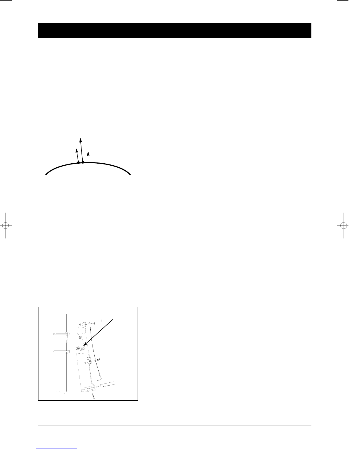
Alignment with a satellite.
Leave the screws loose on the mast bracket until you have set the final position!
After fixing the antenna at its location, you should have it point southwards with the LNB in front.
The antenna height is set using the scale on the mounting plate.
To set the height, bend the antenna up and down carefully, until
the desired number of degrees is set.
The specified values can naturally only apply for vertically
mounted masts or wall brackets.
When setting the angle, do not pull on the LNB mounting arm
(risk of breaking!).
As illustration
39746_BDA_0604_eng #38 29.06.2004 14:22 Uhr Seite 48

49
4. Infor ation on direct satellite reception
39746
39745
EUROPE A TRA 19,2° east HOTBIRD 13° east
Brussels 30,1 31,2
Sarajewo 39,4 39,1
Copenhagen 26,3 26,6
allinn 22,4 21,9
Helsinki 21,6 21,0
Marseilles 38,1 39,5
Paris 31,6 33,0
Athens 45,7 44,6
London 28,3 29,8
Edinburgh 23,2 24,6
Dublin 24,7 26,6
Milan 36,7 37,5
Rome 41,2 41,5
Zagreb 37,2 37,2
Riga 25,1 24,5
Wilna 27,4 26,7
Amsterdam 28,7 29,7
Oslo 21,7 22,0
Vienna 34,6 34,6
Salzburg 34,8 35,1
Warsaw 30,2 29,8
Lisbon 36,4 39,6
Stockholm 22,7 22,5
Bern 34,8 35,8
Bratislava 34,7 34,6
Ljubijana 36,8 37,0
Palma de Mallorca 41,1 43,0
Madrid 37,7 40,2
Prague 32,4 32,6
Budapest 35,4 35,1
GERMANY A TRA 19,2° east HOTBIRD 13° east
Kiel 27,5 27,8
Hamburg 28,3 28,8
Rostock 27,9 28,3
Berlin 29,7 30,0
Bremen 28,6 29,2
Hanover 29,5 30,0
Düsseldorf 30,2 31,1
Kassel 30,6 30,9
Dresden 31,3 31,6
Wiesbaden 31,6 32,4
Nürnberg 32,8 33,3
Saarbrücken 32,3 33,2
Stuttgart 33,2 33,9
Munich 34,2 34,7
The following
setting angles
apply for the
various locations:
39746_BDA_0604_eng #38 29.06.2004 14:22 Uhr Seite 49

50
4. Infor ation on direct satellite reception
39746
39745
For precise alignment of the antenna, the complete cabling must now be connected.
The television and the receiver should be located in the immediate vicinity of the antenna.
It is almost impossible to align the reception system by “shouting” e.g. from a distant television. A SAT
finder (art. no. 37351) or the signal strength indicator on a digital receiver is ideal for aligning the antenna.
Leave the equipment disconnected from the mains supply until cabling is complete!
Connect the antenna cable to the LNB. Carefully introduce the copper-coloured internal conductor of the
cable into the LNB socket. Place the thread of the plug directly onto the socket and screw the plug as
tightly as you can by hand. Fix the other end of the cable to the jack on the satellite receiver in the same
way (LNB IN).
With a scart cable, connect the scart socket of the receiver (TV) to the scart socket of your television.
Your cabling now looks like this:
RECEIVER
LNB
AT ANTENNA
Please insert the provided batteries into the remote control.
Now connect your television and the receiver to the mains.
Press the Stand By button on the receiver or on the remote control.
It may be necessary to switch your television into so-called A/V mode. You can do this with the remote
control on your television. The procedure is different for each television unit. The relevant button could be
marked 0,AV or EXT. Please refer to the instructions for your television.
39746_BDA_0604_eng #38 29.06.2004 14:22 Uhr Seite 50
51
4. Infor ation on direct satellite reception
39746
39745
You must now move the preset antenna in millimetre steps, with the screws only hand-tight. Please note
that there must not be any obstacles between antenna and reception direction, and that you must not
stand in front of the antenna area. When you have mounted the antenna precisely southwards, as
described above, and have set a height angle as specified in the table, turn the antenna slowly to the left,
i.e. to the east. (If the antenna is being installed in astern urope, turn it slowly to the west).
When moving the antenna, observe the screen or any signal indications provided (e.g. Sat finder/Digital
receiver). When a signal/TV picture appears, switch between a few programmes on the receiver to
check whether the antenna is aligned to the correct satellite. When the signal quality has reached its
maximum, you should also move the height angle up and down slightly, in the smallest steps, to further
optimise the quality.
If you do not obtain any reaction or only a weak signal level, you should alter the height angle by a few
millimetres up or down and start the satellite search again by swivelling to the side.
When you have optimally set the antenna, tighten the screws on the antenna. Observe the screen at the
same time, as sometimes the antenna is moved slightly during fixing and the signal strength decreases
again.
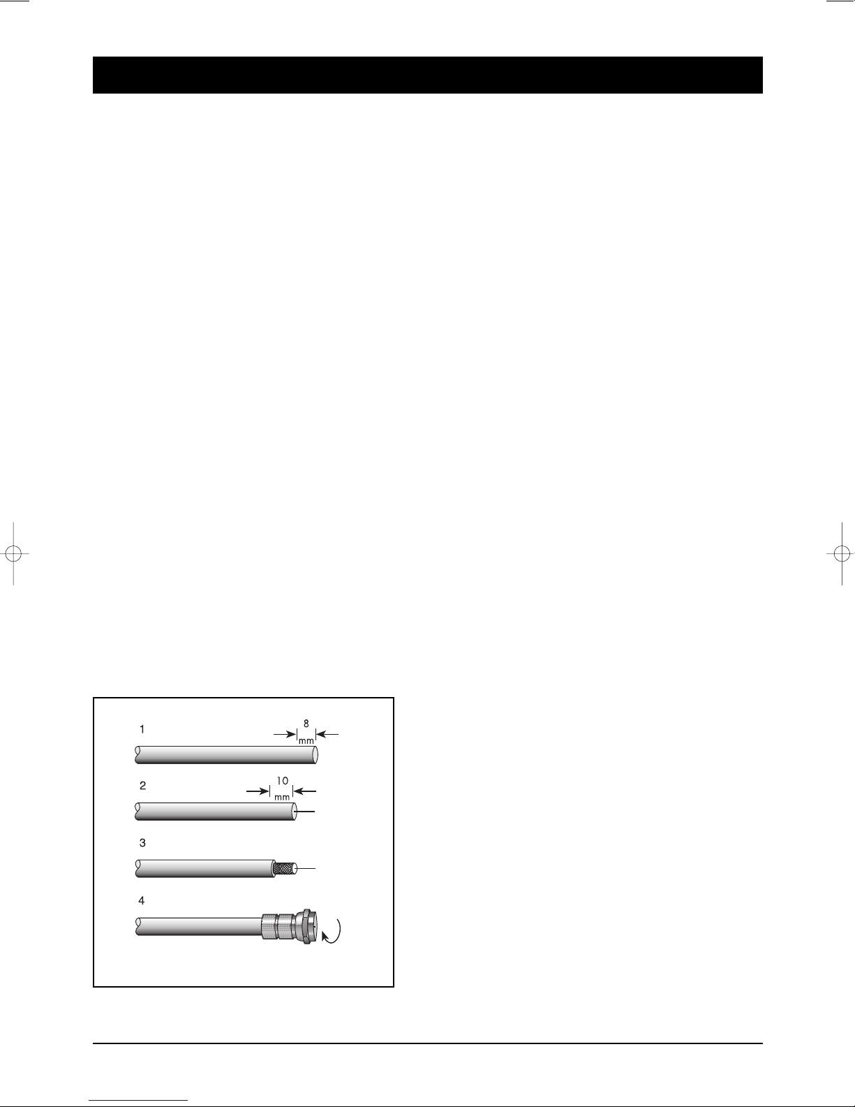
Fitting an F-plug, if you need to shorten your cable
IMPORTANT: Please proceed with great caution when fitting the F-plug. Failure to comply with the
following instructions could cause malfunctions or destruction of the SAT receiver!! – Please use only
continuous antenna cables.
• Strip the cable for a length of 8 mm as far as the
internal conductor (with a sharp knife).
• Remove the protruding wires of the shielding braid.
• Remove 10mm of the plastic casing until the shielding
braid is bared.
• Make sure that no wires of the shielding braid can
touch the internal conductor.
• Carefully screw the F-plug onto the cable, until the
internal conductor terminates flush with the front edge
of the F-plug. The shielding braid is now connected to
the F-plug.
• Check the F-plug for short circuits. Look into the F-plug
from the front; the internal conductor must be located
on its own in the centre and must not be touched by
any wires of the shielding braid!
39746_BDA_0604_eng #38 29.06.2004 14:22 Uhr Seite 51

52
5. Operating ele ents, front of device
5.1 Operating ele ent: Rear side of device
39746
39745
3 2 7541
1. LED: TV/STB
R MOT
(Indication for remote control function)
STANDBY
2. Display:
During theSTANDBY mode, the current time is
displayed.
When the power is ON, the current status is
displayed (TV/Radio/Menu).
3. CHANNEL :
The channel buttons are to change channels.
4. VOLUME :
Controls for volume or channel list.
5. OK: Choise for channel list and sub menu.
6, MENU:
7. 2 CAM modules slots in PCMCIA standard
(only for DVR 9600)
CAM modules are not included!
1. LNB 1 IN: Connects the satellite antenna cable.
2. LNB 1 OUT: Use it to connect to another receiver or
LNB 2 IN.
3. LNB 2 IN: Connects the satellite antenna cable.
4. LNB 2 OUT: Use it to connect to another STB.
5. 0/12V OUTPUT: Choose the LNB on the antenna.
6. VIDEO OUTPUT (yellow): Coaxial video output.
7. AUDIO OUTPUT (red): Audio output right.
8. AUDIO-LEFT OUTPUT (white): Audio output left.
9. TV CART: Connects the TV Scart.
10.VCR CART: Connects the VCR Scart.
11. /PDIF: Optical output for Digital Audio
12.R 232: Service device.
6
1 3 5 7 9
24 6 8 11 1210
39746_BDA_0604_eng #38 29.06.2004 14:22 Uhr Seite 52

53
6. Re ote control unit (RCU)
39746
39745
1.
POWER Button Switch the DVR between Operation and Standby mode.
2. MUTE Button nable / Disable the Audio.
3. UHF Button OPTIONAL – No function
4. TV/ TB Button Change the terrestrial TV and STB mode.
5.
LEEP Button Display the sleep time. At the sleep time, the power
is automatically turned OFF and the DVR goes to the STANDBY mode.
6. Numeric Buttons (0-9) Select the TV or Radio service channels
and menu options.
7. RECALL Button Select the previously viewed channel.
8. INFO Button Display the program information box on the Screen
and remove it. Display the extended event information when the
information box is displayed.
9. GUIDE Button Display the PG on screen when available.
Remove PG when PG is displayed.
10. TV/ Radio Button Select the TV/Radio mode.
11. MENU Button Display the Menu on screen or return to previous
menu from submenu.
12. OUND Button Select Sound Track and L FT/ RIGHT /MONO /
ST R O sound. Select the multifeed channel if multifeed is available.
13. V+/V- Buttons Adjust the volume (Increase / Decrease).
Change the value of the selected item in Menu.
14.
P+/P- Buttons Service up or down through the available services.
Move the selection bar in Menu.
15.
OK Button Display Channel List on screen. Select an item in the menu.
16. FAV Button Display the favorite channel list.
17. UBTITLE Button Activate the subtitle selection window. Select
the subtitle language in the list.
18. EXIT Button Return to the previous menu and the screen.
19.
TELETEXT Button nable the teletext with software emulation.
20. Button Fast rewind when the progress bar is displayed.
Start reverse playback. Change the speed of reverse playback.
21. Button Display the progress bar of time shifting or
playback when no progress bar is displayed.
Start playback with normal speed.
Return to normal speed from trick mode.
22. Button Start fast forward or fast motion playback.
Change the speed of forward playback.
23. Button Start slow motion playback.
Change the speed of slow motion playback.
24. Button Stop time shifting, playback or recording.
25. Button Start recording.
26. Button Pause the playback and live picture.
27. Button Display the Satellite List Box.
28. Button 29. Button 30. Button 31. Button
Above buttons is a kind of function key. So, the function in each OSD
Screen can be referred in each instruction message in help window.
32. Button Select the period for repeated playback or cut out.
While inserting the cells please ensure that
the polarity is right! The polarity is denoted
in the cell area. Cells: 2 cells, size AAA,
UM-4, consumed micro or R03 cells
constitute special waste – please dispose
them properly! Reach, app. 6 m.
1
3
2
5
7
27
19
14
13
18
6
4
16
13
8
21
21
22
25
31
32
23
30
10
12
24
26
29
17
28
9
14
20
11
39746_BDA_0604_eng #38 29.06.2004 14:22 Uhr Seite 53

54
7. Connections
39746
39745
Connection to the SAT antenna
The DiS qC technology allows a large number of connection variants e.g.:
• A permanently aligned SAT antenna
• Two permanently aligned SAT antennae or Multifeed antennae with DiS qC 2-way switch (art. no. 3932)
• 4 permanently aligned SAT antennae with a DiS qC 4-way switch (art. no. 3934)
• 2 permanently aligned Multifeed antennae with DiS qC 4-way switch (art. no. 3934)
• A rotating DiS qC 1.2 rotor system, combined with several permanently aligned antennae
TIP: One or more Universal LNBs (reception converters) are required to receive satellite programmes. The
following technical data should be stated on the adhesive label of the LNB: 10.6 GHz (or 10,600 MHz) and
9.75 GHz (or 9,750 MHz) for the so-called oscillator frequencies. No other values or data are relevant, and
the receiver is ready for operation after connection.
Proceed with the utmost caution when preparing the antenna cable! As voltages and switching signals are
transported via the antenna cable, you must make sure that the shielding braid and the aluminium foil
have good contact with the F-plug and that no short-circuit occurs in the inter-
nal conductor of the cable! After screwing on the F-plug, check that the inter-
nal conductor is not being touched by any of the wires of the shielding braid.
A signal strength indicator is provided for aligning the antenna. Slowly swivel
the antenna southwards, observing the signal display on the screen. If you
cannot find a signal, change the inclination of the antenna a little. When
aligning for the first time, it is advisable to directly connect the antenna and
receiver using the shortest possible antenna cable, in order to exclude potential
error sources
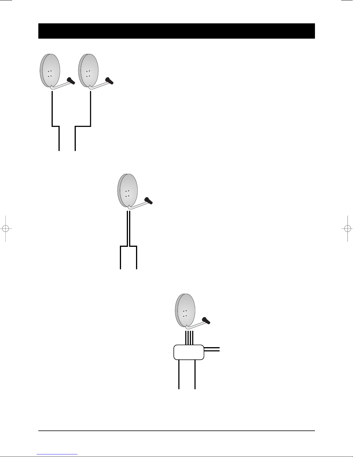
For fixed or rotating antenna systems with
1x Universal ingle LNB.
Only one cable will be used between LNB and
receiver. Setting in menu “LNB settings”:
feed-through.
Both tuner will receive only signals from one
SAT-IF selection (H/V Low/High).
Remark: Independent use of both tuners for
record and play is limited!
Analogue SAT receiver
nstallation:
1 Single LNB
Examples:
39746_BDA_0604_eng #38 29.06.2004 14:22 Uhr Seite 54
55
7. Connections
39746
39745
For fixed or rotating antenna system with
2x Universal ingle LNB.
Two cables will be used between LNB and receiver.
Setting in menu “LNB settings”: separated.
For fixed or rotating antenna system with
1x Universal Twin LNB
Two cables will be used between LNB and receiver.
Setting in menu “LNB settings”: separated.
For fixed or rotating antenna system
1x Universal Quattro LNB plus multi-switch
4 cables will be used between LNB and receiver/
multi-switch. Setting in menu “LNB settings”:
separated.
nstallation:
2 Single LNB
nstallation:
1 Twin LNB
nstallation:
Quattro LNB
39746_BDA_0604_eng #38 29.06.2004 14:22 Uhr Seite 55
56
7. Connections
39746
39745
Connecting to the TV unit
You use a SCART cable for connecting to the TV set. If you have a TV with a 16:9 screen, for example, you
can adjust the settings to match your TV set in the receiver's screen menu. The default screen format is 4:3.
If your TV set does not have a Scart socket, use an appropriate adapter or use the 3 cinch outputs
Connecting to a video recorder
Connect the video recorder and the satellite receiver using a Scart cable. By means of the Scart socket it
is possible to record SAT programmes and to loop the playback of video cassettes through to the TV Scart
socket.
If your video recorder does not have a Scart socket, use an appropriate adapter or use the 3 cinch outputs
Connecting to a stereo system
Analogue: The sound of the TV and radio programmes can be reproduced via your stereo system.
Connect the two audio cinch sockets to a free input of your hi-fi system (e.g. AUX, Line IN, CD or Tuner).
Inputs with the designation “Phono” are not suitable!
Digital: Connect the receiver and your AC3/surround system to the optical digital output of the
SAT receiver.
VCR
TV
AC3/SURROUND (optical)
HIFI
230 V
39746_BDA_0604_eng #38 29.06.2004 14:22 Uhr Seite 56

57
8. Getting started
39746
39745
Press the Power button to operate the DVR from the STANDBY mode. Now, the Info Box will appear
for a given time and disappear. By pressing info button, the Info Box will remain on the screen. The
display time of the Info Box is adjustable in the ystem etting menu of the Main menu.
If the current broadcast has PG ( lectronic Program Guide) with it, press the guide button to see not
only the current channels but also other channels PG without any time constrains.
Also, press button to reserve and save the current service and to watch the broadcast
automatically when it starts.
IMPORTANT: Before taking charge of your new DVR, some important technical settings are essential.
• First, press the M NU button on the RCU to make the Main Menu
appear.
• Go to the LNB Setting item in the Installation menu and press OK
button.
• Choose the right parameters for Satellite Name, Tuner Select, Connection
Type, LNB Frequency, LNB Power, 22KHz, DiS qC 1.1 and DiS qC 1.0.0
• Set the Motorized DiS qC1.2 and the USALS items according to your
antenna, LNB and satellite settings. If the right Satellite Name and LNB
Frequency were not found in the list, call the dealer for satellite
information.
If you are not sure, please use LNB frequency setting 9750/10600 and
put LNB power to “on”.
• Then, press button at Channel Search item and go to the Channel
Search menu.
• Set the Search Mode to the Auto. (Manual, Advanced or SMATV Search)
• Select the Start Search... item and press OK button.
• The search procedure will take a while.
Press OK button when the searching process is finished to
confirm and save the new channel list.
• For further information, please refer to the LNB Setting part of M NU
OP RATIONS in this manual.
39746_BDA_0604_eng #38 29.06.2004 14:22 Uhr Seite 57

58
9. Menu operations
39746
39745
Now this chapter assumes that the DVR system has been installed correctly,
meaning:
• The satellite antenna for the DVR has been installed, connected to the
DVR.
• The DVR is connected to the TV.
• The RCU has batteries and ready to control the DVR.
If the DVR has not been installed or connected properly, please refer to the
INSTALLATION menu on this manual.
Many of the functions of the DVR are available from the Main Menu. Press
menu button to open it.
Various time modes can be set, such as the current time, the Power On/Off
time and the Sleep Time.
The exact local present time can be adjusted by using the GMT, the Time
Offset and the Mode sub menus.
PLEA E NOTE: Configure the Local Time before adjusting the Wakeup Tiem,
Power Off Time or the Sleep Time.
I-1. Time etting
Press button at Local Time Setting item in the Time Setting menu to
open the Local Time Setting menu. Inside Local Time Setting menu, There
are 5 sub menus: Mode, Local Time, GMT, Time Offset and GMT Collection.
Mode
By using and buttons, you can select on of the Auto/Manual mode.
The Auto mode updates the time settings automatically by the GMT received
from the broadcast and the Time Offset you have inserted. The Auto mode is
recommended.
Local Time
The Local Time is adjustable only when the Mode is in the Manual mode.
Adjust the current time, if necessary, by using the numeric buttons and
and buttons.
GMT
GMT is referred to the standard time of Greenwich. It cannot be changed.
Time Offset
The current time of the local area can be inserted. In another words, insert
the time difference of the local time zone from the GMT. For example, if the
local area is Seoul (the time difference from the GMT is 9), insert 9:00. The
time is adjustable by using and buttons, 15 minutes at a time.
GMT Collection
Modify this setting only, in case GMT world clock synchronisation should be
used from special transponder.
. System Setting
39746_BDA_0604_eng #38 29.06.2004 14:22 Uhr Seite 58

59
9. Menu operations
39746
39745
B. Timer
Use the and buttons to select the On/Off mode. If the Timer item is
set on ON, the Wakeup Time item, the Wakeup Channel item and the Power
Off Time item becomes adjustable.
C. Wakeup Time
The Wakeup Time item sets up the time the DVR automatically turns on.
Inserts the preferable Wakeup Time by using numeric-buttons and
the and buttons on the RCU. To disable the wakeup function, make
the Timer item Off.
D. Wakeup Channel
The Wakeup Channel item automatically turns the DVR to the preset channel
when automatically turns on by the Wakeup function.
E. Power Off Time
The Power Off Time menu sets the time of the DVR automatically turns off.
F. leep Time
The Sleep Time item is similar to the Power Off menu. The Sleep Time
function turns off after the adjusted sleep time.
39746_BDA_0604_eng #38 29.06.2004 14:22 Uhr Seite 59

60
9. Menu operations
39746
39745
I-2. Parental Control
Password to various menus can be configured. The PIN Code box will auto-
matically appear when this menu is selected. The default PIN Code is 0000.
A. Censorship
The Censorship item blocks programs according to each specific setting.
Use and buttons to select the items below.
No Block: Access to everyone.
4-18 (age): Inaccessible for viewers within each minimum age limit if a
maturing rating of the event is same or lower than the age
limit.
Total Block: Access to no one without PIN code.
If the channel is limitation free, the block function will not work.
In case of inaccessible, the DVR asks the PIN Code and check the age limit.
B. Change PIN Code
Go to the Change PIN Code item to configure new PIN Code. Press OK
button, then a box will appear on the screen. nter the PIN code by using
the numeric buttons on your RCU.
C. Access Control
The Access Control menu controls access to following items:
• Time Setting
• Language Setting
• A/V Output Setting
• Organizing Channels
• Organizing Favorites
• Installation
• IRD Lock.
Press and buttons to Locked/Unlocked the access. Locked means
controlling the access to the specific menus with the PIN Code system. The
default PIN Code is 0000.
39746_BDA_0604_eng #38 29.06.2004 14:22 Uhr Seite 60

61
9. Menu operations
39746
39745
I-3. Language etting
There are many languages available for the menu.
A. Menu Language
It is an item for changing the language of the Main menu.
Select the language that the menus will be shown in.
nglish / French / Deutsch / Italian / Spanish / Arabic / Greek / Turkish /
Danish / Swedish / Norwegian / Dutch / Russian / Polish / Persian
B. ubtitle Language
It is an item for changing the language of the subtitle.
As long as the services support it, the subtitle language is changeable by
pressing button on your RCU.
nglish / French / Deutsch / Italian / Spanish / Arabic / Greek / Turkish /
Danish / Swedish / Norwegian / Dutch / Russian / Polish / Persian / Disable
C. Audio Language
It is an item for changing the language of the Audio.
If more than one audio language is transmitted, you may select one
language among the languages transmitted by pressing button.
nglish / French / Deutsch / Italian / Spanish / Arabic / Greek / Turkish /
Danish / Swedish / Norwegian / Dutch / Russian / Polish / Persian
* The supported language can be changed without any notice.
39746_BDA_0604_eng #38 29.06.2004 14:22 Uhr Seite 61

62
9. Menu operations
39746
39745
I-4. A/V Output etting
The PVR has many A/V Outputs. Control this menu properly according to
external components connected to the PVR. Configurations concerning Audio
and Video can be made here.
A. TV Type
Select your TV standard. For automatic PAL/NTSC selection, set it to Multi.
B. Video Output
Select the mode of Video output among RGB, S-Video, YUV and CVBS on TV
SCART by using and buttons.
C. VCR CART Type
Select the VCR SCART type either Standard or xternal A/V. In case of
xternal A/V, the source of TV SCART Output will be selected between VCR
SCART input and internal AV by pressing button on the RCU. In case of
Standard, it will be done automatically by the SCART functionality.
D. TV Aspect Ratio
Select your TV screen format. Select 4:3 or 16:9 mode by using and
buttons.
E. 16:9 Display Format
If you have a TV set with the 4:3 picture format and transmission is in 16:9,
you can select the display format. Select the Letter Box or Center extract by
using and buttons.
F. ound Mode
It allows you to configure the sound mode. Select the Stereo, Mono, Left and
Right mode by using and buttons.
The Sound mode is configurable later on by using button on your RCU.
I-5. O D Transparency
Adjust the OSD transparency of all the menus. The available levels are
ranging from 0% to 50%.
I-6.Info Box Display Time
Adjust the time-out of the Info Box. Set the period of time that the Info Box is
displayed on screen. The adjustable time is 0 to 30 seconds, No info box and
Never Hide.
I-7. Info Box Position
Adjust the position of the Info Box. It allows you to change the position by
using and buttons.
39746_BDA_0604_eng #38 29.06.2004 14:22 Uhr Seite 62

63
9. Menu operations
39746
39745
This menu can be used to rename, reorder, lock, hide and delete TV
Services.
A. Browse
Press OK button. Now, browsing through the Organizing Channels is
possible. Press assigned buttons on the help message.
B. Rename
Use and buttons to select Rename item and press OK
button to move the cursor to the Channel List.
Press OK button to display keyboard, and rename the channel.
After renaming it, be sure to save it by pressing
OK button at Save item.
C. Move
You can reorder and move the service to the preferred position. Mark the
desired channel to move and press OK button. Use and
buttons to choose the Move mode.
D. Lock
You can restrain and lock the services. From here, locking (and later
unlocking) channels in any of the lists is possible e.g. in order to prevent
children from watching it. If a locked service is selected, you should enter
the PIN code in order to enjoy it.
E. kip
You can hide and skip the services. In order to unlock the skip function,
press OK button on the skipped channel. The skipped channels will
not be visible on the channel list.
F. Delete
Press OK button to delete channels. The delete function differs from
the skip function as it deletes the channel completely. Whereas, the skip
function just makes the channel invisible.
NOTE: Deleted channels are permanently deleted. The only way to recover
them is to perform a new channel search.
G. ort
You can sort and rearrange the channel list.
. Organizing Channels
39746_BDA_0604_eng #38 29.06.2004 14:22 Uhr Seite 63

64
9. Main enu
39746
39745
This mode is helpful in adding and deleting services to and from the favorite
group. Under the menu Organizing Favorites, there are three different
modes:
Fav List , Fav CHs and TV or Radio Ch List.
On the Fav List mode, four standard lists are selected as the default menus:
News, Sports, Movie and Music. Up to 30 lists including these lists can be
added and renamed. When deleting a service, select a service in the Fav
CHs section and press the assigned button on the help message.
To add services into Favorites, locate the cursor to the desired service in Ch
List and press OK button.
To delete a service from Favorites, locate the cursor to the service in
Fav CHs and press OK button.
To record the service you want, you have to set the following options. You
can record the service immediately. To reserve a recording, you have to use
Timer Setting function in System Setting at Main menu. You can go to the
Timer Setting menu directly by selecting Timer Setting item in this menu,
too.
IV-1. atellite
Press OK button to display the satellite list. Select a satellite that
includes the channel to be recorded.
IV-2. Channel
Press OK button to display the channel list. Select a channel to be
recorded.
IV-3. Mode
There are two recording modes.
To record the selected service immediately, select the Quick mode.
To record current event including the data in the time shifting buffer, select
Current Event mode. The Current Event mode is valid only when the event
information of the channel exists.
IV-4. Duration
To change the duration of the recording time, press and button.
IV-5. File Name
To change the file name of the service to be recorded, press
OK button at this item.
IV-6. tart
To start recording immediately, press OK button at this item. For
reservation you may use Timer Setting in System Setting menu.
IV-7. top
To stop recording immediately, press OK button at this item.
V. Recording
. Organizing Favorites
39746_BDA_0604_eng #38 29.06.2004 14:22 Uhr Seite 64
Table of contents
Other Sky Master Receiver manuals

Sky Master
Sky Master DXS 23 User manual

Sky Master
Sky Master DCI 9410 User manual

Sky Master
Sky Master DCI 35 User manual

Sky Master
Sky Master DX 7 User manual

Sky Master
Sky Master DS 66 User manual

Sky Master
Sky Master DVR 9200 User manual

Sky Master
Sky Master DXR 8000 User manual

Sky Master
Sky Master DCX 10 CI User manual

Sky Master
Sky Master DVR 7500 User manual

Sky Master
Sky Master DCI 9210 User manual


