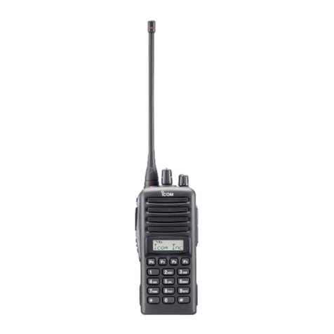
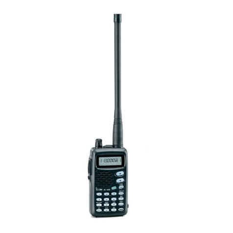
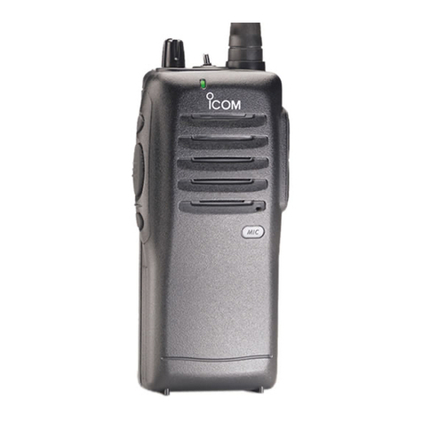
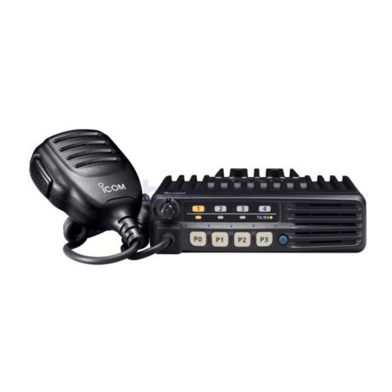
Icom IC-120 Installation instructions

i
INTRODUCTION
FOREWORD
READ ALL INSTRUCTIONS carefully before using
the IC-A120/IC-A120E vhf air band transceiver.
KEEP THIS FULL MANUAL, because it contains
important operating information that may be useful in
the future.
The BASIC MANUAL is supplied with the transceiver.
Icom, Icom Inc. and the Icom logo are registered trademarks
of Icom Incorporated (Japan) in Japan, the United States,
the United Kingdom, Germany, France, Spain, Russia,
Australia, New Zealand and/or other countries.

1PANEL DESCRIPTION
1-2
Front panel
qVOLUME CONTROL KNOB
Adjusts the audio output level.
wSTATUS INDICATOR
➥Lights red while transmitting.
➥Lights green while receiving.
eUP/DOWN KEYS [∫]/[√]
Push to select an operating channel, frequency,
and menu items.
rPOWER KEY [ ]
➥Hold down for 1 second to turn the power ON or
OFF.
➥Push to exit the Menu mode.
tENTER/MHz/GRP KEY [ ]/[MHz]/[GRP]
➥Push to save entered data, a selected item, and
so on in the Menu mode.
➥Push to open the “MEMORY” menu in the
Memory mode.
➥Push to enter the MHz digit Selection mode in
the VFO mode*.
* For only EXP, USA, and EUR versions.
yMENU/CLEAR KEY [MENU]/[CLR]
➥Push to enter the Menu mode.
➥Push to cancel entered data, or to return to the
previous screen in the Menu mode.
uSQUELCH ADJUSTMENT/LOCK KEY [SQL]/[ ]
➥Push to open the squelch adjustment window
(p. 2-3).
➥Hold down for 1 second to turn the Key Lock
function ON or OFF (p. 7-6).
iPRIORITY CHANNEL/DUALWATCH KEY
[PRI]/[DUAL]
➥Push to select the Priority channel.
➥Hold down for 1 second to turn ON Dualwatch
operation, push to turn it OFF.
oSCAN KEY [SCAN]
➥Push to start or stop a scan.
➥Hold down for 5 seconds to select whether or not
to lockout the displayed channel (p. 7-3).
!0 MICROPHONE CONNECTOR
Connect the supplied or an optional microphone.
qe
!0
SPEAKERFUNCTION DISPLAY
w r
tyuio

1PANEL DESCRIPTION
1-3
Function display
qTX/BUSY ICON
➥Displays “TX” while transmitting.
➥Displays “BUSY” while receiving.
wBLUETOOTH ICON
Displayed when a Bluetooth® headset is connected
to the transceiver.
eLOCKOUT ICON
Displayed when the selected channel is locked out.
rSCAN/CHANNEL ICON
➥Displays “SCAN” while scanning.
➥Displays “PSCAN” while Priority scanning.
➥Displays “CH XXX”*1for 5 seconds when you
change the channel in the Memory mode.
tGROUP NAME READOUT
Displays the group name*2.
yMEMORY NAME READOUT
Displays the memory name if it is entered*2.
uFREQUENCY READOUT
Displays the operating frequency*2.
iCHANNEL READOUT
Displays the selected channel number*2.
oOPERATING MODE ICON
➥Displays “MEM” in the Memory mode*2.
➥Displays “PRI” when the Priority channel is set in
the Memory mode.
➥Displays “VFO” in the VFO mode*3.
*1 XXX represents the channel number.
*2
Displayed depending on the Indication Type setting in the
Menu mode (p. 7-7).
*3 For only EXP, USA, and EUR versions.
RX
qwe r
iu
t
y
o

2-1
Section 2BASIC OPERATION
Turning ON the transceiver ..................................................2-2
DEntering the password .....................................................................2-2
Receiving and transmitting ..................................................2-2
Adjusting the squelch...........................................................2-3

2BASIC OPERATION
2-2
Turning ON the transceiver
Hold down [ ] for 1 second to turn ON the power.
If the transceiver is preset for a start-up password,
enter the 6 digits password.
While in the Password Entry mode, “PASSWORD” is
displayed.
DEntering the password
Enter the password in the following manner.
KEY
NUMBER
0
5
1
6
2
7
3
8
4
9
Example:
If the password is 513824, push [SCAN], [PRI/DUAL],
[MENU/CLR], [MENU/CLR], [SQL/ ], and then push
[ /MHz/GRP].
• Note that each key represents 2 digits. That means,
“123456” and “678901” are entered in exactly the same
way (requires no multiple or extended pushing.)
• The entered password will not be displayed.
• If “PASSWORD” does not disappear after entering, the
entered password is incorrect. Turn OFF the transceiver,
and then try again.
Receiving and transmitting
1. Setting the frequency
Setting the frequency in the Memory mode
1) Open the “MEMORY” menu.
➥Push [ /MHz/GRP].
2) Select “GROUPS” item.
➥Push [∫] or [√], and then push [ /MHz/GRP].
3) Select a desired group.
➥Push [∫] or [√], and then push [ /MHz/GRP].
4) Select a desired channel.
➥Push [∫] or [√].
Setting the frequency in the VFO mode
(For only EXP, USA, and EUR versions.)
1) Switch the transceiver to the VFO mode.
➥Select “VFO MODE” group in the Menu mode
and then push [ /MHz/GRP].
MENU > VFO MODE/MEMORY MODE
2) Set the MHz digit.
➥Push [ /MHz/GRP], and then push [∫] or [√].
• The MHz digit blinks.
3) Exit the MHz digit Selection mode.
➥Push [ /MHz/GRP] again.
4) Set the kHz digit.
➥Push [∫] or [√].
TIP: You can select the channel spacing in the “CH
SPACING” item*.
*The menu may not be displayed, depending on the
transceiver’s presettings. Ask your authorized Icom
dealer or transceiver administrator for details.
CAUTION: In Canada, use of 8.33 kHz Channel
Spacing of this radio is strictly prohibited and shall
not be used.
2BASIC OPERATION
2-3
Adjusting the squelch
Adjust the squelch to mute undesired noise when no
signal is received.
1) Open the “SQL” window.
➥Push [SQL/ ].
2) Adjust the squelch.
➥Push [∫] or [√] to select the desired squelch
level.
2. Receiving
When receiving a signal, “BUSY” is displayed and
audio is heard.
• Rotate volume control knob to adjust the audio level.
• Adjust the squelch if necessary. See ‘Adjusting the squelch’
to the right for details.
3. Transmitting
1) Hold down [PTT], and then speak at your normal
voice level.
• “TX” is displayed.
2) Release [PTT] to receive.
Information
To maximise the clarity of the signal, hold the
microphone about 5 to 10 cm (2 to 4 inches) from your
mouth.
Receiving and transmitting (Continued)

3-1
Section 3SCAN OPERATION
Scan types..............................................................................3-2
DMemory channnel scan....................................................................3-2
DPriority scan .....................................................................................3-2
DVFO scan.........................................................................................3-2
Scan settings .........................................................................3-2
DSelecting Scan types .......................................................................3-2
DSetting the Resume timer ................................................................3-2
DOn-Hook scan..................................................................................3-2
DSetting the stop/TX channel.............................................................3-2

The IC-A120/IC-A120E have different types of scan
described below to search for signals.
DMemory channel scan
Repeatedly scans memory channels belonging to the
same group except locked out channels.
DPriority scan
While scanning the Memory channel, Priority watch
checks for a signal on the selected Priority channel.
DVFO scan
(For only EXP, USA and EUR versions.)
Repeatedly scans all frequencies over the entire band.
Customize the Scan settings in the Menu mode. When
you push [SCAN], the transceiver starts scanning
according to the settings described below.
DSelecting Scan types
Select the desired scan type in the “SCAN TYPE” item
before scanning (p. 7-6).
MENU > SETTINGS > SCAN > SCAN TYPE
DSetting the Resume timer
Set the period of time to resume scanning after the
receiving signal disappears (p. 7-6).
MENU > SETTINGS > SCAN > RESUME TIMER
DOn-Hook scan
The transceiver scans for signals while the
microphone is on the hook, depending on the setting
(p. 7-6).
MENU > SETTINGS > SCAN > ON-HOOK SCAN
DSetting the stop/TX channel.
Select the channel that the On-Hook scan stops on
when you remove the microphone from the hook, and
the channel to transmit on when you push [PTT] while
the Dualwatch function is ON (p. 7-6).
MENU > SETTINGS > SCAN > STOP/TX CH
3SCAN OPERATION
3-2
Scan types
Mch 1
Mch 2
Mch 3
Mch 200
Locked out
channel
Lowest
frequency
Highest
frequency
Start
Scan
Jump
Priority
channel
Mch 1
Mch 2
Mch 3
Mch 200
Locked out
channel
NOTE: The Scan function may be disabled,
depending on the transceiver’s setting. Ask your
authorized Icom dealer or transceiver administrator
for details.
Scan settings

4-1
Section 4MEMORY OPERATION
General description...............................................................4-2
Editing a Memory channel.................................................... 4-2
DEditing the memory name................................................................4-2
DDeleting a Memory channel .............................................................4-2
Entering contents into the Memory channels.....................4-3

4MEMORY OPERATION
4-2
General description
The IC-A120/IC-A120E has 200 memories to store
frequently used channels. You can assign the stored
channel to up to 10 groups.
You can edit pre-entered Memory channel contents,
depending on the transceiver’s presettings.
DEditing the memory name
To edit a memory name, follow the steps below.
1. Setting the frequency in the Memory mode
1) Open the “MEMORY” menu.
➥Push [ /MHz/GRP].
2) Select “GROUPS” item.
➥Push [∫] or [√], and then push [ /MHz/GRP].
3) Select a desired group.
➥Push [∫] or [√], and then push [ /MHz/GRP].
4) Select a desired channel.
➥Push [∫] or [√].
2. Editing the memory name
1) Open the “MEMORY NAME” item.
MENU > MEMORY MANAGE > EDIT >
MEMORY NAME
2) Enter a desired name.
➥Push [∫] or [√] to select the desired character.
• Push [SCAN] to select the character group.
You can enter the characters listed below.
• Push [MENU/CLR] to clear the entered character.
• Push [PRI/DUAL] to move the cursor to the left, and
push [SQL] to move the cursor to the right.
• You can enter up to 12 characters.
3) Return to the “EDIT” menu.
➥Push [ ]/[MHz]/[GRP].
4) Save the entered name.
➥Select the “OVERWRITE” item and then push
[ ]/[MHz]/[GRP].
• The transceiver automatically exits the Menu mode.
• The entered memory name is displayed.
• If the memory name is not displayed, check the
Indication Type setting in the Menu mode (p. 7-7).
Editing a Memory channel
A to Z, a to z, 0 to 9, (space)
! " # $ % & ' ( ) * + , - . / : ; < = > ? @ [ \ ] ^ _ ` { | } ~
DDeleting a Memory channel
You can delete an unwanted memory channel.
1. Setting the frequency in the Memory mode
1) Open the “MEMORY” menu.
➥Push [ /MHz/GRP].
2) Select “GROUPS” item.
➥Push [∫] or [√], and then push [ /MHz/GRP].
3) Select a desired group.
➥Push [∫] or [√], and then push [ /MHz/GRP].
4) Select a desired channel.
➥Push [∫] or [√].
2. Deleting a Memory channel
Select the “DELETE” item and then push
[]/[MHz]/[GRP].
MENU > MEMORY MANAGE > DELETE

4MEMORY OPERATION
4-3
You can enter contents into the Memory channels
in the VFO mode, depending on the transceiver’s
presettings.
1. Setting the frequency in the VFO mode
1) Set the MHz digit.
➥Push [ /MHz/GRP], and then push [∫] or [√].
• The MHz digit blinks.
2) Exit the MHz digit Selection mode.
➥Push [ /MHz/GRP] again.
3) Set the kHz digit.
➥Push [∫] or [√].
2. Entering a memory name (p. 7-3)
1) Open the “MEMORY NAME” item.
MENU > MEMORY WRITE > MEMORY NAME
2) Enter a desired name.
➥Push [∫] or [√] to select the desired character.
• Push [SCAN] to select the character group.
You can enter the characters listed below.
A to Z, a to z, 0 to 9, (space)
! " # $ % & ' ( ) * + , - . / : ; < = > ? @ [ \ ] ^ _ ` { | } ~
• Push [MENU/CLR] to clear the entered character.
• Push [PRI/DUAL] to move the cursor to the left, and
push [SQL] to move the cursor to the right.
• You can enter up to 12 characters.
3) Return to the “MEMORY WRITE” menu.
➥Push [ ]/[MHz]/[GRP].
3. Setting the Lockout setting (p. 7-3)
Select whether or not to lockout the selected channel
while scanning.
1) Open the “LOCKOUT” item.
➥Push [∫] or [√], and then [ ]/[MHz]/[GRP].
2) Select the Lockout setting for the channel.
➥Select “OFF” or “ON” and then push
[ ]/[MHz]/[GRP].
• Returns to the “MEMORY WRITE” menu.
Entering contents into the Memory channels
4. Selecting a group (p. 7-3)
Select the group to store the selected channel in.
You can select one of up to 10 groups, depending on
the transceiver’s setting.
1) Open the “GROUP” item.
➥Push [∫] or [√], and then [ ]/[MHz]/[GRP].
• The group list is displayed.
2) Select a desired group.
➥Push [∫] or [√], and then [ ]/[MHz]/[GRP].
• Returns to the “MEMORY WRITE” menu.
5. Writing the contents into the Memory channel
Select the “WRITE” item and then push
[ ]/[MHz]/[GRP].
NOTE: The VFO mode is for only EXP, USA, and
EUR versions. If you are using the transceiver
without the VFO mode, you cannot enter the
contents into memory channels.

The Priority channel enables you to have quick access
to a specic channel. You can set one of the Memory
channels as the Priority channel.
DSetting the Priority channel
1) Open the “PRIORITY CH” menu.
MENU > SETTINGS > FUNCTIONS > PRIORITY
CH
•
The channel set as the Priority channel is displayed.
•
“OFF” is displayed if no channel is set as the Priority
channel.
2) Open the “GROUP” menu.
➥Push [ /MHz/GRP].
3) Select the desired group.
➥Push [∫] or [√] and then push [ /MHz/GRP].
4) Select the desired channel.
➥Push [∫] or [√] and then push [ /MHz/GRP].
•
“Returns to the “PRIORITY CH” menu.
•
“The selected channel is displayed as the Priority
channel.
5OTHER FUNCTIONS
5-2
Priority channel
NOTE: The Priority channel may be disabled,
depending on the transceiver’s setting. Ask your
authorized Icom dealer or transceiver administrator
for details.
Dualwatch operation
Dualwatch monitors the Priority channel while a VFO*
or Memory channel is selected.
If a signal is received on the Priority channel,
Dualwatch changes to the Priority channel until the
Priority signal disappears. Dualwatch then returns to
the selected other channel.
*For only EXP, USA, and EUR versions.
Hold down [PRI/DUAL] for 1 second to turn ON the
Dualwatch function.
•
The Priority channel is displayed under the selected
channel.
•
The Priority channel’s name may be displayed, depending
on the Indication Type setting. See page 7-7 for details.
•
When a signal is received on the Priority channel, “PRI”
blinks and the Priority channel is displayed larger than the
selected channel.
• If the
“
STOP/TX CH
” item’s setting in the menu mode
(p. 7-6)
is set to
“
PRIORITY CH,
” “TX:PRI” is displayed as
shown below.

6-1
Section 6Bluetooth®OPERATION
Operating Bluetooth®............................................................6-2
Electromagnetic interference............................................... 6-2
Pairing with a headset...........................................................6-3
Connecting a paired headset ...............................................6-3
Setting AF output .................................................................. 6-3
Disconnecting a headset ......................................................6-4
Unpairing a headset ..............................................................6-4

6Bluetooth® OPERATION
6-2
If the UT-133A Bluetooth®unit is installed in the
transceiver, you can connect a Bluetooth®headset.
When you connect the VS-3 Bluetooth®headset
to the transceiver, you can wirelessly transmit and
receive the headset audio.
The VS-3 has a [PTT] switch, so you can transmit in
the same way as using the transceiver’s [PTT] switch.
Communication range of Bluetooth
®
is approximately
10 meters (32.8 ft).
Operating Bluetooth®
The Bluetooth
®
communication range may vary,
depending on your operating environment.
Microwave ovens or Wireless LANs may cause
interference. In that case, stop using those devices
or move away from them.
This Bluetooth
®
headset has a usable range. If
communication is unstable, move within the range.
Bluetooth®
Electromagnetic interference
When you use a Bluetooth
®
headset, pay attention to
the following:
Bluetooth
®
devices operate in the 2.4 GHz band.
The 2.4 GHz band is also used by other devices, such
as Wireless LAN products, microwave ovens, RFID
systems, amateur radio stations, and so on.
When using the Bluetooth
®
headset near such
devices, interference may occur, causing a decrease
in communication speed, and an unstable connection.
In such cases, use the headset away from the other
devices, or stop using those headsets.
Transceiver with the
UT-133A Bluetooth®unit
Optional vs-3
Bluetooth®headset

6Bluetooth® OPERATION
6-3
Pairing with a headset
These instructions describe pairing with the VS-3
Bluetooth®headset. You can pair a maximum of 7
Bluetooth®headsets with the transceiver.
• If you try to pair a Bluetooth®headset to a transceiver that
already has 7 headsets paired with it, the oldest headset
will automatically be unpaired.
1. Turning ON transceiver’s Bluetooth® function
1) Open the “BLUETOOTH FUNC” item.
MENU > SETTINGS > BLUETOOTH
> BLUETOOTH FUNC
2) Activate the Bluetooth®unit.
➥Select “ON” and push [ /MHz/GRP].
2. Entering the Pairing mode of the VS-3
• See the VS-3’s instruction manual for details.
3. Pairing the Bluetooth® headset
1) Open the “DEVICE SEARCH” item.
MENU > BLUETOOTH > PAIR/CONNECT
> DEVICE SEARCH
2) Search for a headset to pair.
➥Select “HEADSET” and push [ /MHz/GRP].
• The found headsets are displayed.
• “NOT FOUND” is displayed if no headset is found.
• Push [MENU/CLR] to cancel searching.
• The headset name changes to its Bluetooth®device
address in 5 seconds.
3) Select the desired headset to pair.
➥Push [∫] or [√] and then push [ /MHz/GRP].
• A passkey or PIN code may be required to
pair, depending on the headset. Refer to
your headset’s instructions for details.
4) Exit the Menu mode.
➥Push [ ].
• “ ” is displayed if the headset is correctly paired.
If you have a previously paired headset, follow the
steps below to connect it.
1) Open the “PAIR/CONNECT” menu.
MENU > BLUETOOTH > PAIR/CONNECT
• The paired headsets are displayed.
2) Select the desired headset to connect.
➥Push [∫] or [√] and then push [ /MHz/GRP].
• “CONNECT” and “UNPAIR” is displayed.
3) Connect the headset.
➥Select “CONNECT” and then push
[ /MHz/GRP].
• The check mark “4” in the box is displayed.
4) Exit the Menu mode.
➥Push [ ].
Setting AF output
You can select the AF output option in the
“AF
OUTPUT” item.
MENU > SETTINGS > BLUETOOTH
> HEADSET SET > AF OUTPUT
HEADSET: Outputs audio to the
connected Bluetooth®
headset.
HEADSET & SPEAKER: Outputs audio to both the
connected Bluetooth®
headset and the
transceiver’s speaker.
Connecting a paired headset

6Bluetooth® OPERATION
6-4
Disconnecting a headset Unpairing a headset
You can disconnect a headset without canceling the
pairing.
1) Open the “PAIR/CONNECT” menu.
MENU > BLUETOOTH > PAIR/CONNECT
• The connected headsets are displayed.
2) Select the desired headset to disconnect.
➥Push [∫] or [√] and then push [ /MHz/GRP].
• “DISCONNECT” is displayed.
3) Disconnect the headset.
➥Push [ /MHz/GRP], and then select [YES].
• The check mark “4” in the box disappears.
4) Exit the Menu mode.
➥Push [ ].
You can unpair a Bluetooth®headset.
Before unpairing a connected
headset
, disconnect it.
1) Open the “PAIR/CONNECT” menu.
MENU > BLUETOOTH > PAIR/CONNECT
• The paired headsets are displayed.
2) Select the desired headset to unpair.
➥Push [∫] or [√] and then push [ /MHz/GRP].
3) Unpair the headset.
➥Select “UNPAIR” and push [ /MHz/GRP].
• The headset name disappears from the “PAIR/
CONNECT” menu.
4) Exit the Menu mode.
➥Push [ ].

7-1
Section 7MENU MODE
Using the Menu mode ...........................................................7-2
Menu mode items ..................................................................7-3
VFO MODE/MEMORY MODE group ..................................... 7-3
MEMORY WRITE group.........................................................7-3
DMEMORY NAME .............................................................................7-3
DLOCKOUT........................................................................................7-3
DGROUP............................................................................................7-3
DGROUP NAME ................................................................................7-3
DWRITE .............................................................................................7-3
MEMORY MANAGE group .................................................... 7-4
EDIT .................................................................................7-4
DMEMORY NAME .............................................................................7-4
DLOCKOUT........................................................................................7-4
DGROUP NAME ................................................................................7-4
DOVERWRITE ...................................................................................7-4
DELETE ...........................................................................7-4
BLUETOOTH group ...............................................................7-4
PAIR/CONNECT ..............................................................7-4
DDEVICE SEARCH............................................................................7-4
PAIRING STANDBY.........................................................7-4
SETTINGS group ...................................................................7-5
FUNCTIONS ....................................................................7-5
DCH SPACING...................................................................................7-5
DPRIORITY CH..................................................................................7-5
DNOISE LIMITING .............................................................................7-5
DTIME OUT TIMER............................................................................7-5
DMIC KEY CUSTOMIZE ....................................................................7-5
DLOCK FUNCTION............................................................................7-6
DCI-V..................................................................................................7-6
SCAN ...............................................................................7-6
DSCAN TYPE.....................................................................................7-6
DRESUME TIMER .............................................................................7-6
DON-HOOK SCAN ............................................................................7-6
DSTOP/TX CH ...................................................................................7-6
DISPLAY..........................................................................7-7
DLCD BACKLIGHT ............................................................................7-7
DLCD CONTRAST.............................................................................7-7
DINDICATION TYPE ..........................................................................7-7
SOUNDS..........................................................................7-7
DKEY BEEP .......................................................................................7-7
DBEEP LEVEL ...................................................................................7-7
DSIDE TONE......................................................................................7-7
DSPEAKER OUTPUT ........................................................................7-7
BLUETOOTH................................................................... 7-8
DBLUETOOTH FUNC ........................................................................7-8
DAUTO CONNECT ............................................................................7-8
DHEADSET SET ................................................................................7-8
DDATA DEVICE SET..........................................................................7-9
DDEVICE INFO .................................................................................7-9
DDEVICE INITIALIZE.........................................................................7-9
INFORMATION................................................................7-9
DVERSION.........................................................................................7-9
Other manuals for IC-120
3
This manual suits for next models
1
Table of contents
Other Icom Transceiver manuals
Popular Transceiver manuals by other brands

Entel
Entel HX446E user guide

Vecima
Vecima VistaMax OBR3500 Installation and operation guide

Vertex Standard
Vertex Standard EVX-534 Service manual

Comtech EF Data
Comtech EF Data CSAT-5060 Installation and operation manual

Vecima
Vecima VistaMAX OBR3650 Installation and operation guide

Radio Shack
Radio Shack TRC-485 owner's manual