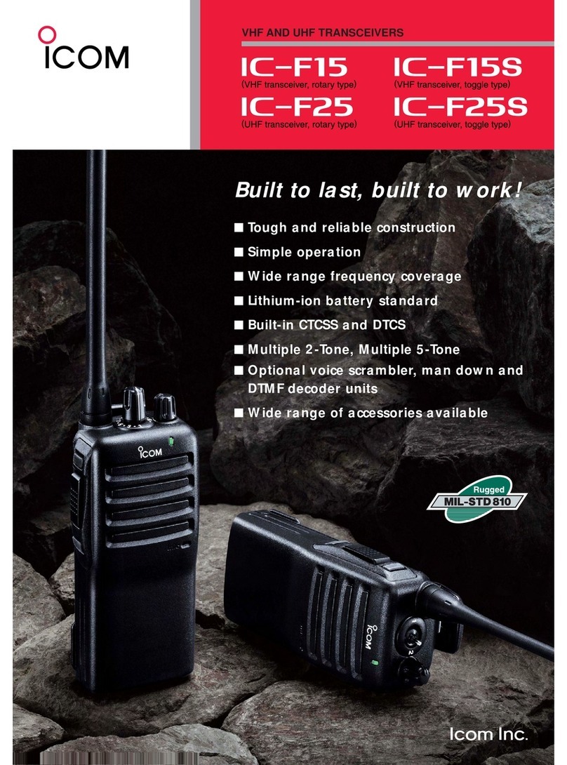
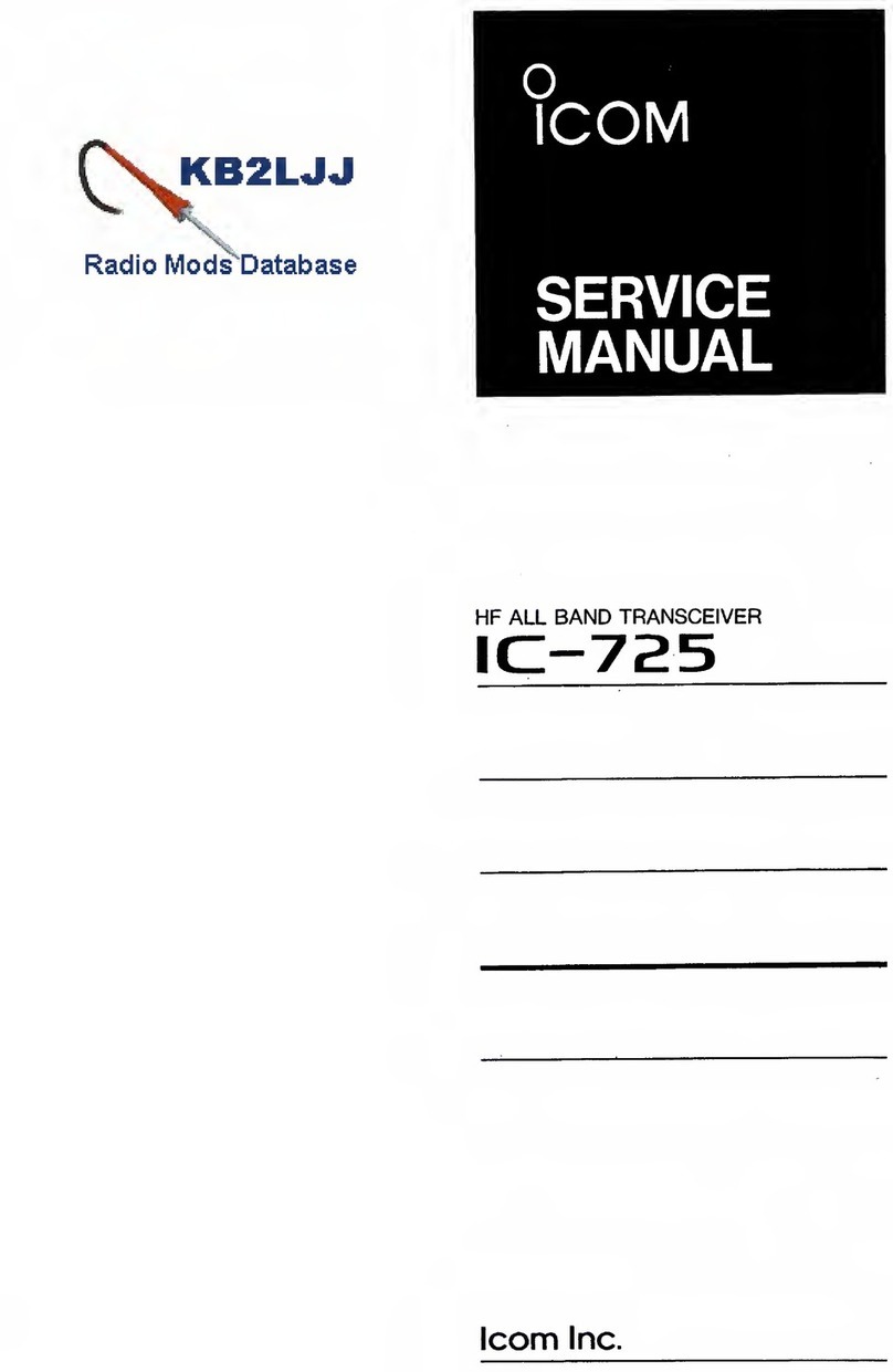
Icom IC-735 User manual

FeTRANSCE !EP IC-715
NEIN
,-
77111
. ma.
7
.
1111
SCAN ,
DOWN
AM,MO
WWI
,
NI-C1.1
UP
PliONES
MIC
0
ICOM
INSTRUCTION MANUAL
HF ALL BAND TRANSCEIVER
GENERAL COVERAGE RECEIVER
I
C 735
Icom Inc.

FOREWORD
Thank you very much for choosing this ICOM product.
The IC-735 is a complete
H
F, all mode transceiver and general coverage receiver contained in one small,
compact package developed by ICOM utilizing the latest computer technology and precise, advanced
HF
engineering.
To fully enjoy the benefits of this high-performance transceiver, please study the instruction manual
thoroughly prior to operation. Also, feel free to contact an authorized ICOM dealer if you have any
questions relating to the operation of this model.

TABLE OF CONTENTS
SECTION
1 SPECIFICATIONS
1
SECTION
2 DESCRIPTION
3
SECTION 3 CONTROL FUNCTIONS
5
3 - 1 FRONT PANEL
6
3 - 2 FREQUENCY DISPLAY
10
3 - 3 SWITCH PANEL
11
3 - 4 REAR PANEL
12
SECTION
4 INSTALLATION AND CONNECTIONS
15
4 - 1
UNPACKING
15
4 - 2 INSTALLATION RECOMMENDATIONS
15
4 - 3 ANTENNA
15
4 - 4 MICROPHONE
16
4 - 5 CW KEY
16
4 - 6 POWER SUPPLY
17
4 - 7 GROUND
18
4 - 8 LITHIUM BATTERY REPLACEMENT
18
4 - 9 FUSE REPLACEMENT
18
4 - 10 REAR PANEL CONNECTIONS
19
SECTION
5 SYSTEM INTERCONNECTIONS
20
5 - 1
LINEAR AMPLIFIER
20
5 - 2 ANTENNA TUNER
21
5 - 3 RTTY OPERATION
21
5 - 3 - 1
CONNECTIONS
22
5-3-2
FREQUENCY READOUT
22
5 - 4 INSTALLING OPTIONAL ELECTRONIC KEYER
23
5 - 5 INSTALLING OPTIONAL CW NARROW FILTER
23
5 - 6 ACCESSORY CONNECTORS
24
SECTION
6 OPERATING INSTRUCTIONS
25
6 - 1 SETTINGS
25
6 - 2 BASIC OPERATION
26
6 - 2 - 1
FREQUENCY SELECTION
26
6 - 2 - 2
MODE SELECTION
27
6 - 2 - 3
VFO A/B SELECTION
27
6 - 2 - 4
VFO MODE/MEMO MODE SELECTION
28
6 - 3 RECEIVING
28
6 - 4 TRANSMITTING
29

6 - 5 OPERATION
29
6 - 5 - 1
SSB OPERATION
29
6 - 5 - 2
CW OPERATION
31
6 - 5 - 3
AM OPERATION
32
6 - 5 - 4
FM OPERATION
33
6 - 6 SPLIT (DUPLEX) OPERATION
34
6 - 7 MEMORY CHANNEL OPERATION
34
6 - 8 SCAN OPERATION
35
6 - 9 MICROPHONE UP/DOWN FUNCTION
37
6 - 10 FILTERS
38
6 - 10 - 1
PASSBAND TUNING (P.B.T.)
38
6 - 10 - 2 NOTCH FILTER
38
6 - 10 - 3 FILTER SWITCHES
38
6 - 11 FREQUENCY CALIBRATION
39
6 - 12 SWR CHECKING
39
SECTION
7 BLOCK DIAGRAM
40
SECTION
8 INSIDE VIEWS
41
8 - 1
MAIN UNIT SIDE
41
8 - 2 PL UNIT SIDE
42
8 - 3 ADJUSTMENT LOCATIONS
43
8 - 3 - 1
MAIN UNIT SIDE
43
8 - 3 - 2
PL UNIT SIDE
44
8 - 4 DISASSEMBLY DIAGRAMS
45
SECTION
9 OPTIONAL UNITS
46
SECTION 10 SCHEMATIC DIAGRAM
SEPARATE

SECTION 1 SPECIFICATIONS
1 - 1 GENERAL
Number of semiconductors
Frequency coverage
: Transistors
124
F ETs
18
Diodes
258
ICs (Includes CPU)
42
Ham Bands
1.8MHz
2.0MHz
3.4MHz
4.1MHz
6.9MHz
7.5MHz
9.9MHz 10.5MHz
13.9MHz 14.5MHz
17.9MHz 18.5MHz
20.9MHz — 21.5MHz
24.4MHz 25.1MHz
27.9MHz — 30.0MHz
General Coverage (Receive Only)
0.1MHz — 30.0MHz
Usable temperature range
—10
°
C — +60
°
C (+14
°
F — +140
°
F)
Frequency control
: CPU based 10Hz step digital PLL synthesizer.
Independent Transmit/Receive frequency available.
Frequency readout
: 6 digit 100Hz illuminated LCD
Frequency stability
: Less than ±200Hz from 1 minute after switch ON to 60 minutes.
Less than ±30Hz after 1 hour at 25
°
C
Less than ±500Hz in the range of 0
°
C — +50
°
C
Power supply requirements
: 13.8V DC ±15% (negative ground)
Current drain 20A maximum at 200W input.
AC power supply is available for AC operation.
Current drain (at 13.8V DC)
: Transmitting
At 200 watts input
Approx.
20A
Receiving
At maximum audio output Approx.
1.5A
Squelched
Approx.
1.2A
Antenna impedance
: 50 ohms unbalanced
Weight
: 5kg
Dimensions
: 94(107)mm(H) x 241(244)mm(W) x 2391272)mm(D)
(
) Dimensions include projections.

1 - 2 TRANSMITTER
RF power
Emission modes
: SSB (A3J) : 200 watts PEP input
CW (A1) : 200 watts input
AM (A3) : 40 watts output
FM (F3)
: 200 watts input
Continuously adjustable output power from 10 watts to maximum.
: A3J (J3E) SSB (Upper and Lower Sideband)
Al (A1A) CW
A3 (A3E) AM
F3 (F3E) FM
Harmonic output
: More than 40dB below peak power output.
Spurious output
: More than 50dB below peak power output.
Carrier suppression
: More than 40dB below peak power output.
Unwanted sideband
: More than 50dB down at 1000Hz AF input.
Microphone
: 600 ohm electret condenser microphone with push-to-talk switch and scanning
buttons.
1 - 3 RECEIVER
Receive system
: Triple conversion superheterodyne with continuous bandwidth control.
Receive modes
: A3J (J3E) SSB (Upper and Lower Sideband)
Al (A1A) CW
A3 (A3E) AM
F3 (F3E) FM
Intermediate frequencies
1st: SSB, AM, FM
70.4515MHz
CW
70.4506MHz
2nd: SSB, AM, FM
9.0115MHz
CW
9.0106MHz
3rd: SSB, CW, AM, FM
455kHz
Sensitivity
: SSB, CW
(PRE AMP ON on 1.6 30MHz)
0.1 — 1.6MHz
Less than 1.0pV for 10dB S/N
1.6'- 30MHz
Less than 0.15pV for 10dB S/N
AM (When selecting NARROW FILTER.)
0.1 — 1.6MHz
Less than 6pV for 10dB S/N
1.6 — 30MHz
Less than 1,uV for 10dB S/N
FM
1.6 30MHz
Less than 0.5pV for 12dB SINAD
Squelch sensitivity
: FM 0.3pV
Selectivity
: SSB, CW 2.3kHz/-6dB, 4.0kHz/-60dB
AM
6.OkHz/-6dB, 18kHz/-50dB
FM
15kHz/-6dB, 30kHz/-60dB
Spurious and image response rejection : More than 80dB
Notch filter attenuation
: More than 30dB
Audio output
More than 3 watts/10% distortion with 8 ohm load.
Audio output impedance
8 ohms
All stated specifications are subject to change without notice or obligation.

SECTION 2 DESCRIPTION
n
COMPLETE HF RADIO
•
COMPACT SIZE
•
ALL BAND, ALL MODE,
ALL SOLID-STATE
•
GENERAL COVERAGE RECEIVER
The small size of the IC-735, only 94mm(3.7")(H) x 241mm(9.5")
(W) x 239mm(9.4")(D), simplifies installation in most mobile and
portable situations such as automobiles, airplanes, boats or suitcases.
The IC-735 covers all Amateur HF frequencies from 1.8MHz to
30MHz, including the three new bands of 10MHz, 18MHz and
24MHz. It offers not only SSB, but also CW, AM and FM operating
modes. All circuits in the IC-735, including the driver and final
power stages, are completely solid-state, and the transceiver provides
about 100 watts output.
The IC-735 features general coverage receive capability with a tuning
range from 100kHz to 30MHz continuous, made possible by an
up-conversion system which uses a high side IF and a CPU control
system.
•
RTTY OPERATION POSSIBLE
The rear panel of the IC-735 has easy-to-access terminals for AFSK
(audio frequency shift keying) RTTY operation.
n
OUTSTANDING RECEIVER PERFORMANCE
•
105dB DYNAMIC RANGE
•
ICOM'S DFM SYSTEM INSTALLED
•
PBT AND NOTCH CONTROL
The IC-735 has a 105dB dynamic range with a 70.4515MHz first IF
circuit which uses two quality crystal filters that virtually eliminate
spurious responses.
The ICOM DFM (Direct Feed Mixer) feeds the incoming signals
directly into a high level first mixer developed by ICOM. This
advanced system produces a higher spurious response rejection ratio,
a higher receiver sensitivity and a wider dynamic range.
The IC-735 has a built-in Passband Tuning system that allows
continuous center frequency adjustment of the IF passband. Addi-
tionally, a sharp IF notch filter provides clear reception even in the
presence of strong interference.
•
PREAMP AND ATTENUATOR INCLUDED
Both a 10dB preamplifier plus a 20dB attenuator are installed as
standard equipment. The preamplifier increases receiver sensitivity
while the attenuator provides added protection from intermodula-
tion problems.
n
SIMPLE PANEL DESIGN
•
ROTARY DIAL DIGITAL TUNING
ICOM's new continuous tuning system features a backlight LCD
SYSTEM
(liquid-crystal display) that closely follows the TUNING CON-
TROL, and provides an extremely accurate readout. The V FO, with
10Hz digital tuning steps, gives the feel of an analog tuning system.
•
EASY-TO-OPERATE, MULTIPURPOSE
TUNING CONTROL
•
CONVENIENT, FRONT SWITCH PANEL
The MAIN TUNING CONTROL plus adjacent switches select either
the 10Hz, 1kHz or 1MHz tuning speed and, also, control band
changes.
The front-mounted SWITCH PANEL is a new idea from ICOM
which groups lesser used controls in one compact area behind a
protective cover.
n
NEWLY DEVELOPED CPU INSTALLED
•
VARIOUS SCANNING FUNCTIONS
Memory Scan allows monitoring of all different memory channels or
only those stored with a particular mode. Programmed Scan
provides scanning between any two programmed frequencies.
Auto-stop Scan functions when a signal is received in any mode.
Mode Selective Scan automatically monitors only those memories
which contain frequencies with the same mode.
•
EASY-TO-READ DISPLAY
•
12 MEMORIES
The new liquid-crystal display with a soft, green illumination pro-
vides good operating frequency visibility even in sunlight, and also
indicates the VFO in use, operating mode, memory channel, split
mode and scan mode.
Twelve programmable memories are provided to store mode and
frequency, and the CPU is backed up by an internal lithium battery
to maintain the memories for up to five years. Scanning of fre-
quencies, memories and bands is possible from either the transceiver
or the IC-HM12 scanning microphone.
•
ADVANCED REMOTE CONTROL SYSTEM
Full communications with a personal computer equipped with an
RS-232C jack is possible by using the serial port mounted on the
rear panel of the IC-735. The computer controls frequency, mode,
VFO A/B selection and memories when an appropriate interface is
used. The serial port uses a standard 1200 baud data rate.
n
OPTIONS AVAILABLE
•
AT-150
The AT-150 HF automatic antenna tuner was developed primarily
for the IC-735 using advanced, state-of-the-art design techniques.
•
PS-55
This is a 13.8V DC, 20A power supply recently developed specifi-
cally for use with the IC-735.
•
AH-2
•
CT-17
The AH-2 HF ALL BAND ANTENNA TUNER can be used to
match all HF amateur bands from *3.5 to 30MHz. One touch of the
TUNE SWITCH and the internal microprocessor in the AH-2 auto-
matically tunes the antenna to the lowest SWR within an average of
2 to 3 seconds.
*1.8 to 30MHz with an antenna of 12 meters or more.
The CT-17 CI-V LEVEL CONVERTER allows you to connect a
personal computer to the IC-735 for external control of operating
frequencies, modes, memory channels, etc.

SECTION 3 CONTROL FUNCTIONS
O
cc
2
O
O
O
O
O

3 - 1 FRONT PANEL
10
POWER SWITCH
® AF GAIN CONTROL
0 SQUELCH CONTROL
MODE SELECT SWITCHES
() TUNING CONTROL
This is a push-lock switch which controls the input DC power to the
IC-735. When the PS-55 AC power supply is used, the switch also
acts as the AC power supply switch. Power is supplied to the
transceiver when the switch is pushed in and locked. Power to all
circuits is cut (except to the PA unit when using a DC power supply)
when the switch is pushed again and released.
This control varies the audio output level in the receive mode.
Clockwise rotation increases the level.
This control sets the squelch threshold level. To turn off the squelch
function, rotate this control completely counterclockwise. To set
the threshold level higher, rotate the control clockwise.
These switches select any one of four operating modes; either SSB,
CW, AM or FM. Each push of the SSB button alternately selects
USB and LSB. Additionally, the "correct" sideband (USB for
10MHz and above, LSB for 7MHz and below) is automatically
selected when the HAM switch is pushed. This is explained in
greater detail in item 8.
Rotate this control clockwise to increase, and counterclockwise to
decrease the frequency. The frequency changes in 10Hz steps in any
mode, although the number of steps per dial revolution auto-
matically increases when the control is rotated more rapidly. This
control is also used to select the operating band while the HAM
button is pushed.
© kHz TUNING RATE SWITCH
This switch sets the tuning rate for 1kHz steps. See Section 6-2-1
for more information.
MHz and HAM buttons have priority over the kHz button.
0 MHz TUNING RATE SWITCH
This switch sets the tuning rate for 1MHz steps. See Section 6-2-1
for more information.
The HAM button has priority over the MHz button.

AM
t,.Q
i
q
n
S.
'n
VFO B
LSB
nnr
-
on
t.
I. LI
VFO A
USE
nrrnn
VFO A
in
ma 2
L7.3
u. u
I
C
12 MEMORY READ SWITCH (MEMO)
VFO MODE
The transceiver functions on ten bands which include all HF Ham
bands from 1.8MHz to 28MHz inclusive. The TUNING CONTROL
selects each Ham band in a continuous cycle as shown below when
the HAM button is pushed.
C) HAM TUNING RATE SWITCH
0 DIAL LOCK SWITCH
—
,
1.8MHz/3.5MHz/7MHz/10MHz/14MHz/18MHz/21MHz/24.5MHz/28MHz/29MHz
CONTINUOUS CYCLE
With the HAM button pushed, the USB mode is automatically
selected on the 10MHz band and above, and the LSB mode is
automatically selected on the 7MHz band and below. See Section
6-2-1 for more information.
The HAM button has priority over both the kHz and MHz buttons.
This switch electronically locks the display frequency, thus deacti-
vating the TUNING CONTROL. This function is useful after the
IC-735 is set to a certain frequency for rag chewing, mobile opera-
tion, etc. Disengage the dial lock by pushing and releasing the
button again.
In the MEMORY CHANNEL mode, this switch activates the
Selective Mode Scan so that memories programmed with one
particular mode may be monitored.
VFO SWITCH
This switch selects VFO A or VFO B for tuning purposes. Each
oush of this button selects one of the two VFOs alternately.
Push "VFO" button.
VFO A
VFO B
.(=>
LSB
I.
LI
Zi
1.
LI
VFO A
0
I1 VFO EQUALIZING SWITCH (A=B)
This switch instantly matches the frequency and mode of operation
of the two VFOs.
The display does not change when the A=B button is pushed,
however confirmation of the equalizing process is possible by
pushing the VFO button to check the frequency and mode of the
opposite VFO.
Push A=B button.
VFO A
VFO B
LSB
nr1CInVFOB
I
I.
L I _I I. L I
This switch selects the MEMORY CHANNEL mode. The "MEMO"
indicator appears on the display, and the "VFO A" or "VFO B"
indicator disappears.
After pushing the MEMO button, the display indicates the frequency,
mode and last memory channel number accessed.
Push MEMO button.
MEMO MODE
The frequency or mode can be changed while in the MEMORY
LSB
MEMO
CHANNEL mode but the new frequency and mode information will
LE
3
nrnn
only be saved if the MW (MEMORY WRITE) button is pushed. See
.
.
u
I
L.
_J
item 14 for more information.

LSB
MD
3.8 _5
LI. LI
n n
VFO A
13 MEMORY CHANNEL UP/DOWN
SWITCHES
DOWN M - CH
U P
AM
n
n
VFO A
CE3
t 1.1 t
LI.
LI
MEMORY CHANNEL number
MEMORY WRITE SWITCH
Displayed frequency and mode are
stored in memory channel 1.
LSB
11
n
VFO B
I.
I 1_1.11
5
0 FREQUENCY TRANSFER SWITCH
Push M
►
VFO
button.
Stored information in MEMO CH-5
transfers to VFO B and displays when
the M
►
VFO button is pushed.
USB
can10
.
05.l7
VFO B 5
NOTE:
When in the MEMORY CHANNEL mode, it is the dis-
played frequency which transfers to the VFO. This is
not necessarily the MEMORY CHANNEL frequency
since the TUNING CONTROL may have been used to
shift the operating frequency. Information stored in the
memory channel remains unchanged after using the
M
►
VFO function.
Each push of these switches increases or decreases the MEMORY
CHANNEL.
In the VFO mode, only the MEMORY CHANNEL number changes
whereas in the MEMORY CHANNEL mode, the MEMORY
CHANNEL number, the memorized frequency and the mode change
with each push of the UP or DOWN button. Pushing these switches
with the dial lock engaged steps through the memory channels
programmed with the same mode.
Push this button to store the displayed operating frequency and
mode of operation into a memory channel. Memory writing is
possible in either the VFO or MEMORY CHANNEL modes. See
page 34 for information on programming the memory channels.
This switch operates differently depending on which mode the
transceiver is in.
1)
In the V FO mode, the frequency and mode stored in the memory
channel displayed transfers to the selected VFO.
2)
In the MEMORY CHANNEL mode, the displayed frequency and
mode transfers to the VFO used immediately prior to changing to
the MEMORY CHANNEL mode.
ED
SCAN START/STOP SWITCH
©SPLIT (DUPLEX) SWITCH
0 RECEIVER INCREMENTAL TUNING
RIT
This switch alternately starts/stops any of the scan functions. The
scan restarts from the stopped frequency in the Programmed Scan
mode, and from the highest memory channel in MEMORY CHAN-
NEL scan modes. See page 35 for a full description of the various
scanning systems available on the IC-735.
This switch selects the relationship of the two VFO frequencies. In
the OFF position, one VFO is for both receive and transmit. In the
ON position, one VFO is for receive while the other VFO is for
transmit. Each push of this button alternately chooses the simplex
and duplex modes. See page 34 for a full description of simplex/
duplex operation.
This control shifts the receiver frequency ±800Hz.
RIT
a
RIT SWITCH/RIT LED
This switch turns the RIT circuit ON and OFF. The RIT LED
illuminates when the RIT function is active.

2
PASSBAND TUNING CONTROL
This control allows continuous tuning of the passband selectivity by
moving the filter center frequency as much as 1.8kHz either side of
the receive frequency in the SSB or CW modes. This feature not
only improves the selectivity, but it can also improve the audio tone.
The normal control position is at the center (12 o'clock), which
provides a filter bandwidth of 2.4kHz in the SSB mode. See page38
for a more detailed explanation.
0 NOTCH FILTER SWITCH
This switch turns the NOTCH FILTER circuit ON and OFF.
0 NOTCH FILTER CONTROL
0 T/R (TRANSMIT/RECEIVE) SWITCH
C) PHONES JACK
MIC CONNECTOR
This control shifts the NOTCH FILTER frequency. Adjust the
control to reduce or eliminate interfering signals. See page 38 for a
more detailed explanation.
This switch is for manually switching from transmit to receive and
vice versa. Set the switch to RECEIVE(out) and the IC-735 is in the
receive mode. Set the switch to TRANSMIT(in) and the transceiver
switches to transmit. When using the PTT switch on the microphone
or the VOX system, the T/R SWITCH must be in the RECEIVE
position.
This jack accepts a standard 1/4 inch headphone plug from head-
phones with an impedance of 4 — 16 ohms. Stereo headphones may
be used without modification.
Connect a suitable microphone to this jack. The supplied IC-HM12
hand microphone or the optional SM-8 desk microphone may be
used. For different microphones, refer to the diagrams on page 16.
FRONT VIEW
® AF OUTPUT
EDMIC
INPUT
C2 +8VDC OUTPUT
© F REQ UP/DOWN
TGND
(microphone ground)
EDGND (PTT ground)
® PTT
®NC
a
NOISE BLANKER (NB) SWITCH
© ATT (ATTENUATOR) SWITCH
PREAMP SWITCH
Push this switch IN to reduce pulse noise such as that generated by
automobile ignition systems. The blanker circuit reduces back-
ground receive noise for more enjoyable operating. Additionally,
the NB LEVEL CONTROL varies the noise blanker threshold level
when the switch is IN.
Push this switch IN to remove the RF amplifier from the receive
path when strong signals interfere with reception, or make "S"
meter readings difficult. For normal operation, leave the switch
OUT.
This switch turns the receiver preamplifier ON and OFF. Push the
switch IN to insert the 10dB preamplifier in the receive path when
using a small antenna or receiving a weak signal for added sensitivity.
The preamp circuit works at frequencies higher than 1.6MHz.

XMIT
RECV
AGC (AUTOMATIC GAIN CONTROL)
SWITCH
CD COMP (SPEECH COMPRESSOR) SWITCH
3 - 2 FREQUENCY DISPLAY
This switch changes the time constant of the AGC circuit. When the
switch is OUT, the AGC voltage reduces slowly for SSB reception.
When the switch is IN, the AGC voltage reduces quickly for either
CW reception or for receiving signals with rapid fading.
This switch turns the speech compressor circuit ON and OFF. The
circuit provides greater talk power by improving the intelligibility of
the transmitted signal over long distances.
The frequency of the IC-735 is displayed on a liquid-crystal display
(LCD). The display indicates the carrier frequency using both MHz
and kHz decimal points when in any mode (USB, LSB, CW, AM,
FM).
Remember, the displayed frequency does not change when using the
R IT function (explained later), although the actual receive fre-
quency does change.
The FREQUENCY DISPLAY shows the mode and whether VFO
A/B, a memory channel, or the SCAN mode is selected, in addition
to the operating frequency.
O LSBUSBCWAM FM'
PR
35
n
t_.
t,
I
I
SCAN
VFO A
VFO B
I
SPLIT
MEMO
j
IL
O
c,
FREQUENCY INDICATOR
VFO INDICATOR
MEMORY INDICATOR
® MODE INDICATOR
® TRANSMIT INDICATOR
® RECEIVE INDICATOR
(I)
SCAN INDICATOR
Shows the operating frequency with 100Hz resolution using 6 digits.
Shows the selected VFO; either
VFO A or VFO B.
Shows whether or not the transceiver is in the MEMORY CHANNEL
mode, plus the selected memory channel number. The letters
"MEMO" appear when the MEMORY CHANNEL mode is selected.
Shows the operating mode; either LSB, USB, CW, AM or FM.
Appears when the transceiver is in the transmit mode.
Appears when the squelch opens in the receive mode.
Shows whether or not the transceiver is in the SCAN mode, in which
case, the letters "SCAN" appear.
® SPLIT INDICATOR
Shows the relationship of the two VFO frequencies. One VFO is for
receive and the other VFO is for transmit when the letters "SPLIT"
appear.

NB
RF
RF
VOX
M IC
LEVEL
GAIN POWER GAIN DELAY
GAIN
AM
CW
METER
VOX
BK-I N
NARROW
ALC
ON
FULL
DOODD
I
WIDE
PO
OFF
SEMI
SPEED
ELEC KEY
MANUAL
Higher sensitivity
Lower sensitivity
VOX
BK -IN
ON
FULL
10 CI
OFF
SEMI
VOX DELAY CONTROL
(VOX time constant)
3 - 3 SWITCH PANEL
® NB LEVEL CONTROL
C) RF GAIN CONTROL
© RF POWER CONTROL
RF
POWER
©
VOX GAIN CONTROL
VOX
GAIN DELAY
This control varies the threshold level of the noise blanker. Adjust
the control to remove noise from the desired signal.
This control varies the gain of the RF stage when the transceiver is
in the receive mode. Slide the control upwards for maximum gain.
Note that as the control slides downwards, the "S" meter needle
rises, and only those signals stronger than the level indicated by the
needle will be heard. In the FM mode, regardless of the control
setting, the RF gain is fixed at the maximum.
This control varies the RF output power from 10 watts to maximum
(SSB:100 watts
PEP,
CW/FM:100 watts, AM:40 watts). Slide the
control upwards to increase the output power.
This control increases and decreases the sensitivity of the VOX
circuit. When operating in the CW mode, semi break-in or full break-
in operation is possible.
©MIC GAIN CONTROL
When operating in the SSB, AM or FM mode, adjust the control so
that the circuit activates with a normal speech level. See page 30 for
more information.
This control changes the transmit to receive switching time. Adjust
it such that transmit to receive switching does not occur during
pauses in normal speech.
For CW operation, adjustment depends on the keying speed used.
Adjust this control for a suitable modulation level while speaking
into the microphone in a normal voice. Slide the control upwards to
increase the gain while monitoring the front panel ALC meter. Set
the control so the meter needle just begins to move within the ALC
zone.
This control also varies the speed of the electronic keyer when this
feature is used.
•

OO
FILTER SWITCHES
AM
CW
NARROW
These switches select the different combinations of the second IF
(9MHz) filter and the third IF(455kHz) filter to improve the receiver
selectivity. These filters function in conjunction with the Passband
Tuning system. See page 31 and 38 for more information.
I
WIDE
© METER SWITCH
This switch selects the meter function when in the transmit mode as
follows:
(1)
ALC: The meter indicates the ALC level. The meter begins to
give an indication when the RF power reaches a certain
value.
(2)
PO:
The meter indicates the relative RF output power.
NOTE:
The meter switch on the rear panel of the transceiver
should be in the PO position in order for the PO meter
reading to be accurate.
CD
VOX SWITCH
CW BREAK-IN SWITCH
g
E LEC-KEY/MANUAL SWITCH
This switch turns the VOX circuit ON and OFF. The automatic T/R
switching VOX circuit functions in the PHONE and CW modes when
the switch is IN. In CW, semi break-in or full break-in operation is
possible.
Push this switch IN for full break-in CW operation and OUT for semi
break-in operation. The VOX SWITCH must also be IN for the
BREAK-IN SWITCH to operate. See page 31 for more information.
When an optional ELECTRONIC KEYER UNIT is installed, push
this switch IN to activate the automatic, iambic keyer, and connect a
keyer paddle to the KEY jack on the rear panel of the transceiver.
See page 32 for more information on the use of the keyer. The unit
installation is described on page 23.
3 - 4 REAR PANEL
0
ANTENNA (ANT) CONNECTOR
Connect a 50 ohm impedance antenna to this connector. The con-
nector mates with a PL-259 plug.
cp
DC POWER SOCKET
Connect the DC power cord from the PS-55 or other suitable power
supply here.

0 GROUND TERMINAL
® RECEIVER ANTENNA OUTPUT JACK
0 RECEIVER INPUT JACK
To prevent electrical shock, TV I, BCI and other problems, be sure to
ground the equipment through the GROUND TERMINAL. For best
results use the heaviest gauge wire or strap possible and make the
connection as short as possible, even in mobile installations.
The receive signals from the ANTENNA CONNECTOR pass through
the transmit/receive antenna switching circuit to this jack. Normally,
the receiver IN and OUT jacks are connected together with a jumper.
The ANTENNA OUTPUT JACK is useful when operating with a
separate receiver or an external preamplifier.
This is an input jack which connects directly to the receiver front
end.
® TRANSVERTER (X-VERTER) JACK
0 EXTERNAL SPEAKER JACK
® KEY JACK
0 ALC JACK
(3
SEND JACK
©REMOTE CONTROL JACK
©ACCESSORY (ACC) CONNECTORS
(1), (2)
13 COMP (SPEECH COMPRESSOR)
LEVEL CONTROL
Connect a suitable transverter to this jack for operation on the
VHF/UHF frequencies. The output is approximately 30mV.
Connect an external speaker to this jack, if required. Use a speaker
with an impedance of 4 16 ohms and remember, the built-in speaker
does not function when using the EXTERNAL SPEAKER JACK.
For CW operation, connect a CW key here using the supplied
standard 1/4 inch, 3-conductor plug. The terminal voltage from
external electronic keyers must be less than 0.4 volts DC.
When using the IC-735 internal iambic keyer, connect an iambic
keyer paddle with a 1/4 inch, 3-conductor plug.
This is an input jack for the Automatic Level Control (ALC) lead
from a linear amplifier. The ALC input voltage must be in the range
from 0 to —4 volts.
This jack connects to the transmit/receive relay, and it is grounded
when the push-to-talk switch is operated.
This is a communications port designed for use with a personal
computer to remotely operate the transceiver functions. The jack
accepts/transmits serial data by using only one signal and one ground
line.
These connectors provide signals such as T/R switching, receiver
output, etc. See page 24 for detailed information.
This control varies the compression level when the COMP SWITCH is
pushed IN. The preset circuit gain is approximately 10dB.
4

O MIC TONE CONTROL
This control varies the transmit audio response. Set the control to
produce the clearest and most pleasing audio. Bass response increases
as the control is rotated counterclockwise.
0 AM CARRIER CONTROL
ANTI-VOX CONTROL
I7 METER SWITCH
S
1
3
5
7 9 +20dB +60dB
RF
0
10
25 50 100
%
SWR
1_
1.52
3
SET
ALC
n
This control changes the transmit AM carrier level. Adjust with the
M IC GAIN set at minimum for a 40 watt carrier or 40% of full scale
indication with the METER SWITCH in the Po position. See page
32 for AM operation.
When using the VOX mode, speaker audio may sometimes activate
the transmitter accidentally. Adjust the ANTI-VOX CONTROL in
conjunction with the VOX GAIN in the IC-735 SWITCH PANEL to
eliminate this undesired T/R switching.
In the transmit mode, this switch selects one of three meter func-
tions.
(1)
Po:
The meter indicates the relative RF output power
provided the METER SWITCH in the SWITCH PANEL
is set to the PO position.
(2)
SET: Place the switch in the SET position to measure the
standing-wave ratio (SWR) of the antenna system.
Adjust the RF POWER CONTROL until the needle rests
at the SET position on the meter.
(3)
SWR: The front panel meter directly reads the antenna system
SWR after calibration as explained in step (2).

SECTION 4 INSTALLATION AND CONNECTIONS
4 - 1 UNPACKING
Carefully remove your transceiver from the packing carton and
examine it for signs of shipping damage. Should any be apparent,
notify the delivering carrier or dealer immediately, stating the full
extent of the damage. It is recommended you keep the shipping
cartons. They will be handy in the event storage, moving, or reship-
ment becomes necessary. Accessory cables, plugs, etc., are packed
with the transceiver. Make sure you have not overlooked anything.
1.
DC Power Cord
1
2.
Phono Plugs
2
3.
External Speaker Plug
1
4.
Spare Fuses (20 amp)
2
5.
Spare Fuses (3 amp)
2
6.
Key Plug
1
7.
Microphone (IC-HM12) and hanger. . 1
8.
Instruction Manual
1
4 - 2 INSTALLATION RECOMMENDATIONS
1.
Avoid placing the IC-735 in direct sunlight, high temperatures
and dusty or humid places.
2.
The temperature of the transceiver usually becomes relatively
high while transmitting. Place any accessory equipment at least 3
centimeters (1 inch) away from the unit so as to provide space for
adequate ventilation. Be sure to keep the PA heatsink and the
area around it clear of obstructions. Also, avoid locations near
heater outlets, air conditioners, etc.
3.
Place the unit so that the controls and switches can easily be
handled, and the frequency display and meter can be seen clearly.
4.
For mobile installations, an optional mounting bracket is
available. Select a location which can support the weight of the
unit, and that does not interfere with the driver in any way.
5.
Use the Ground Terminal!
4 - 3 ANTENNA Antennas play a very important role in radio communication. If the
antenna is inferior, your transceiver cannot give you the best perfor-
mance. A well-matched 50 ohm antenna and feedline will provide
the desired performance. Obtain a quality antenna, preferably one
with high gain, which operates on the bands of interest and install it
as high as possible. Be especially careful when installing the con-
nectors since poor or loose connections greatly reduce the overall
efficiency of the system. Connect the ground terminal of a mobile
antenna, if used, to the body of the vehicle.

Schematic diagram of
IC-HM12
Wiring for straight key.
9
Avoid connecting the ANTENNA CONNECTOR to open feedlines,
and do not transmit under mismatched conditions. Operating the
transmitter under these conditions could result in damage to the
IC-735.
n
MOBILE ANTENNA
4 - 4 MICROPHONE
Since the IC-735 comes standard with a general coverage receiver, it
is recommended that a long-wire antenna and antenna coupler be
used. The coupler will ensure there is a matched condition at all
times. A Ham band antenna generally does not give adequate
performance when used on frequencies for which it was not designed.
ICOM's AH-2 HF ALL BAND ANTENNA TUNER can be easily
bumper mounted for mobile use, offering automatic band switching
and tuning in unison with the IC-735. With a 2.5 meter antenna, the
AH-2 can fully cover 3.5 to 30MHz.
One push of the TUNE SWITCH on the AH-2 automatically changes
the IC-735 emission mode to FM and output power to 10 watts for
tuning the AH-2 on the frequency.
The supplied IC-HM12 electret condenser hand microphone or
optional SM-8 desk microphone may be used. Merely plug it into
the MIC CONNECTOR on the front panel. If you wish to use a
different microphone, make certain it has the proper output level.
Particular care must be exercised when wiring a different micro-
phone since the transceiver internal electrical switching system is
dependent upon the correct connections. Refer to the schematics
for the proper hookup.
4 - 5 CW KEY
For CW operation, connect a CW key to the KEY JACK using the
supplied standard 1/4 inch, 3-conductor plug. See the diagrams for
connection details.
Observe the correct polarity of all leads when wiring. Note that the
keyed voltage when switching with semiconductors or relays with
resistors in the circuit must be less than 0.4 volts.
Other manuals for IC-735
6
Table of contents
Other Icom Transceiver manuals
Popular Transceiver manuals by other brands

Conrad Electronic
Conrad Electronic MC-8 CV-Mobil 80 Operating instruction

Midland
Midland Olympian MO-1008 user guide

Keysight Technologies
Keysight Technologies S9130A Getting started guide

Iridium
Iridium 9522A user guide

MGL Avionics
MGL Avionics V16 User and installation manual

Kenwood
Kenwood TK-760G series Service manual