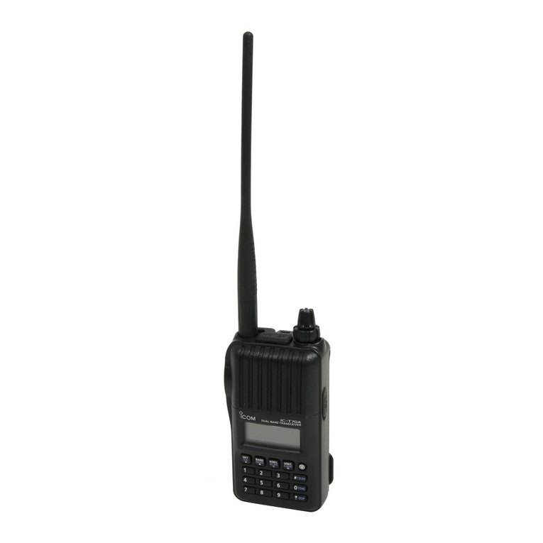
Icom IC-41W User manual

INSTRUCTION MANUAL
i41W
UHF C.R.S.TRANSCEIVER

i
IMPORTANT
READ ALL INSTRUCTIONS carefully before using
the IC-41W UHF C.R.S. transceiver.
KEEP THIS INSTRUCTION MANUAL, as it con-
tains important operating information that may be useful in
the future.
EXPLICIT DEFINITIONS
WORD DEFINITION
RDANGER! Personal death, serious injury or an explo-
sion may occur.
RWARNING! Personal injury, fire hazard or electric
shock may occur.
CAUTION Equipment damage may occur.
NOTE
If disregarded, inconvenience only. No risk
of personal injury, fire or electric shock.
GENERAL INFORMATION
i. The Citizen Band Radio Service is licensed in Australia by
the ACMA Radiocommunications (Citizens Band Radio
Stations) Class Licence and in New Zealand the Ministry
of Economic Development New Zealand (MED). Opera-
tion is subject to conditions contained in the General User
Radio Licence for Citizens Band Radio.
ii. The transceiver must not be operated on channel 5 and
35, unless in an emergency. No voice transmissions are
permitted on channels 22 and 23, as these are used for
data (telemetry/telecommand). The transceiver will inhibit
transmission on channels 22 and 23.
iii. Always listen on a channel (or observe channel busy indi-
cator) to ensure it is not already being used before trans-
mitting.
iv. This transceiver operates on 12.5 kHz channel spacing.
During the changeover period from 25 kHz to 12.5 kHz,
there may be some loss of quality and/or audio level when
12.5 kHz (narrowband) transmissions are received on 25
kHz (wide band) equipment, and vice-versa. There may
also be interference caused by older equipment operat-
ing on channels adjacent to narrowband channels, as the
channel setting on these may cause some ‘overlap.’
Icom, Icom Inc. and the Icom logo are registered trademarks of Icom Incor-
porated (Japan) in Japan, the United States, the United Kingdom, Germany,
France, Spain, Russia and/or other countries.

ii
PRECAUTIONS
CAUTION: MAKE SURE the flexible antenna, bat-
tery pack and jack cover are securely attached to the trans-
ceiver, and that the antenna and battery pack are dry before
attachment. Exposing the inside of the transceiver to dust or
water will result in serious damage to the transceiver.
DO NOT operate the transceiver near unshielded electri-
cal blasting caps or in an explosive atmosphere.
DO NOT
push [PTT] when not actually intending to transmit.
DO NOT use or place the transceiver in direct sunlight or in
areas with temperatures below –30°C or above +60°C.
The basic operations, transmission and reception of the trans-
ceiver are guaranteed within the specified operating tempera-
ture range. However, the LCD display may not be operate
correctly, or show an indication in the case of long hours of
operation, or after being placed in extremely cold areas.
DO NOT modify the transceiver. The transceiver warranty does
not cover any problems caused by unauthorized modification.
DO NOT use harsh solvents such as benzine or alcohol
when cleaning, as they will damage the transceiver surfaces.
BE CAREFUL! The transceiver will become hot when
operating it continuously for long periods of time.
RDANGER! NEVER short the terminals of the battery
pack.
RDANGER! Use and charge only specified Icom bat-
tery packs with Icom radios or Icom chargers. Only Icom bat-
tery packs are tested and approved for use with Icom radios
or charged with Icom chargers. Using third-party or coun-
terfeit battery packs or chargers may cause smoke, fire, or
cause the battery to burst.
RWARNING! NEVER hold the transceiver so that
the antenna is very close to, or touching exposed parts of
the body, especially the face or eyes, while transmitting. The
transceiver will perform best if the microphone is 5 to 10 cm
away from the lips and the transceiver is vertical.
RWARNING! NEVER operate the transceiver while
driving a vehicle. Safe driving requires your full attention—
anything less may result in an accident.

iii
BE CAREFUL! The IC-41W meets IP67* requirements
for dust-tight and waterproof protection. However, once the
transceiver has been dropped, dust-tight and waterproof pro-
tection cannot be guaranteed because of possible damage to
the transceiver’s case or the waterproof seal.
* Only when the jack cover or the optional HM-168LWP is
attached.
Even when the transceiver power is OFF, a slight current still
flows in the circuits. Remove the battery pack or batteries from
the transceiver when not using it for a long time. Otherwise,
the installed battery pack or batteries will become exhausted,
and will need to be recharged or replaced.
MAKE SURE to turn the transceiver power OFF before
connecting the supplied/optional equipment.
This device complies with Standard Aus-
tralia Specification No. AS/NZS 4365-2002
and AS/NZS 4295: 2004.
PRECAUTIONS (Continued)

iv
TABLE OF CONTENTS
IMPORTANT................................................................................i
EXPLICIT DEFINITIONS.............................................................i
GENERAL INFORMATION..........................................................i
PRECAUTIONS.......................................................................... ii
TABLE OF CONTENTS............................................................. iv
1 ACCESSORIES.................................................................1–2
Supplied Accessories■........................................................1
Attaching/Using the Accessories■.......................................1
AntennaD.........................................................................1
Battery PackD..................................................................1
Belt ClipD.........................................................................2
Jack CoverD.....................................................................2
2 UNIT DESCRIPTION.........................................................3–6
Front panel■.........................................................................3
Display■...............................................................................5
3 BASIC OPERATION........................................................7–10
Turning the Power ON■.......................................................7
Battery type■.......................................................................7
Backlight■............................................................................8
Keylock■..............................................................................8
Channel/Zone Selection■....................................................8
Channel SelectionD.........................................................8
Zone SelectionD
(available only when two or more zones are set).....8
Receiving/Transmitting■......................................................9
ReceivingD.......................................................................9
TransmittingD...................................................................9
Priority Channel■...............................................................10
To set the Priority ChannelD..........................................10
To switch to the Priority ChannelD.................................10
To cancel the Priority ChannelD....................................10
Monitor■.............................................................................10
Squelch■............................................................................10
4 SET MODE....................................................................11–15
SquelchD.......................................................................12
CTCSS/DTCSD.............................................................12
Auto Power OFFD..........................................................12
BacklightD......................................................................12
BeepD............................................................................13
Beep LevelD...................................................................13
Mic GainD.....................................................................13
Battery VoltageD............................................................13
Signal MonitorD.............................................................13
Power SaveD................................................................13
TOT (Time-Out Timer)D.................................................14
Lock-outD.......................................................................14
Scan Resume TimerD....................................................14
Scan RestartD...............................................................14
Roger BeepD.................................................................14
Own IDD........................................................................15
5 REPEATER OPERATION ...................................................16
Repeater Operation■.........................................................16

v
6 SCAN.............................................................................17–20
Scanning Preparation■......................................................17
Scan type selectionD.....................................................17
Tag Channel SettingD....................................................17
Scan Resume ConditionD..............................................18
Open Scan■.......................................................................18
Group and Priority Scan■..................................................19
Repeater■..........................................................................20
Repeater search scan flowD..........................................20
7 TONE SQUELCH ..........................................................21–23
Setting Up a CTCSS/DTCS CodeD...............................21
Turning the tone squelch operation ON or OFFD..........23
Setting up and using the pocket BeepD.........................23
8 SELCALL (Selective Calling) ......................................24–27
Calling■..............................................................................24
TX Code Channel SelectionD........................................24
To select a TX code channelD.......................................24
TX code number editD...................................................25
Receiving■.........................................................................26
Receiving an individual call (default setting)D...............26
Recalling a memorised receive selcall codeD...............26
When receiving a group callD........................................26
Quiet Mode■......................................................................27
To monitor the channelD................................................27
To enable selcall muteD.................................................27
Stun■.................................................................................27
9 OTHER FUNCTIONS ....................................................28–30
Smart Ring/ATSD...........................................................28
RX FrequencyD..............................................................29
PTT HoldD....................................................................30
10 BATTERY CHARGING..................................................31–35
Caution■............................................................................31
Charging cautionD.........................................................32
Rapid charging with the BC-160■......................................33
Optional battery chargers■................................................33
AD-106 installationD......................................................33
Rapid charging with the BC-119N+AD-106D.................34
Rapid charging with the BC-121N+AD-106D.................34
11 OPTIONS.......................................................................36–39
MB-93 contents■...............................................................36
Attaching■..........................................................................36
Detaching■........................................................................37
Optional HM-168LWP description■...................................38
Attachment■......................................................................38
BATTERY PACKD..........................................................39
CHARGERSD................................................................39
BELT CLIPSD................................................................39
DC CABLESD................................................................39
OTHER OPTIONSD.......................................................39
12 SPECIFICATIONS ...............................................................40
13 WARRANTY AND REGISTRATION ...................................41
TABLE OF CONTENTS (Continued)
1
1
ACCESSORIES
11
Supplied Accessories■
Belt clip
AC adapter
(for the battery charger)
Battery charger
Battery pack
Flexible antenna
Attaching/Using the Accessories■
AntennaD
Connect the supplied antenna to the antenna
connector as shown.
CAUTION:
•NEVER carry the transceiver by
holding only the antenna.
•DO NOT
connect the antenna other
than listed on page 39.
•
Transmitting without an antenna
may damage the transceiver.
Battery PackD
To attach the battery pack:
Slide the pack in the direction of the arrow (q), until the bat-
tery release button makes a ‘click’ sound.
NOTE: Push on the bottom of the pack to make sure the
release button is firmly locked.
To release the battery pack:
Push the battery release button in the direction of the arrow
(w), then slide the battery pack out.
NEVER release or attach the battery pack when the unit is
wet or soiled. This may result in water or dust getting into
the transceiver/battery pack, which may cause damage to
the transceiver.
NOTE: Keep the battery terminals clean. It's a good idea to
regularly clean them.
q
w
Battery release button

2
1ACCESSORIES
Belt ClipD
To attach the belt clip:
Release the battery pack if it is attached.q
Slide the belt clip in the direction of the arrow (see below)w
until a ‘click’ sound is heard.
To detach the belt clip:
Release the battery pack if it is attached.q
Pinch to lift the clip atwq(see below) and slide the belt clip
out of the holding bracket. (w)
q
w
Jack coverD
To attach the jack cover:
qAttach the jack cover to the [MIC/SP] jack.
wTighten the screws.
w
[MIC/SP] jack
Jack cover
q
q
q
w
CAUTION:
•Attach the jack cover when the op-
tional speaker-microphone is not
used.
•Usethesuppliedscrewsonly.
To detach the jack cover:
qUnscrew the screws using a phillips
screwdriver.
wDetach the jack cover for the speak-
er-microphone.

3
2
UNIT DESCRIPTION
1
2
1
Front panel■
q
w
r
eu
i
y
Microphone
Speaker
t
o!0!1!2
q ANTENNA CONNECTOR
Connects the supplied antenna.
w TOP KEY [TOP]
Toggles Normal (N), Function (F) and Set (S) modes.
In Normal mode
Push to turn Function mode ON. (“F” is displayed)➥
Push and hold for 2 seconds to enter set mode (p. 11).➥
In Function mode
Push to return to Normal mode.➥
When a receive channel is selected (once enabled),➥
push and hold for 2 seconds to enter RX VFO (receive
frequency select) mode. (p. 29
)
NOTE : After 30 seconds in Function mode with no opera-
tion, unit will return to Normal mode.
e SIDE1 KEY [Side1]
In Normal mode
Push to toggle the monitor (open tone squelch) func-➥
tion ON or OFF. (p. 10)
Push and hold for 2 seconds to activate the following➥
functions in order:
•Tone squelch (only receive calls with same tone squelch
code). “T SQL ”appears. (p. 21)
•Pocket beep (informs that a call was missed). “T SQL ë”
appears. (p. 21)
•Notoneoperation.“TSQLë” disappears.
In Function mode
Push to enter squelch setting mode, then push [CH Up]➥
or [CH Down] to set the squelch level. (p. 10)
Push and hold for 2 seconds to turn the ATS (Auto-➥
matic Transponder System) function ON or OFF.
(p. 28)
r PTT SWITCH [PTT] (p. 9)
Push and hold to transmit. Release to receive.➥
A PTT hold function is also available. See page 30 for➥
more information.
t CH UP/CH DOWN KEYS
y VOLUME CONTROL
Rotate to turn power ON or OFF and set operating volume.
u EXTERNAL SPEAKER JACK
Connect an optional speaker microphone. Ensure power is
OFF before connecting external devices.

4
2UNIT DESCRIPTION
i LCD DISPLAY (p. 5)
o SCAN/TAG KEY
In Normal mode
Push to start or stop scanning. This is dependent on➥
tagged channels. (p. 17)
Push and hold for 2 seconds to set or clear displayed➥
channel as tagged. (p. 17)
In Function mode
Push to enter the Selcall code channel selection mode,➥
when a CB channel is selected. (p. 24)
Push and hold for 2 seconds to transmit to the Selcall code➥
channel, when a CB channel is selected. (p. 25)
!0 O.G.P/RS KEY
In Normal mode
Push repeatedly to cycle through open, group and➥
priority scan. (“ ,” “ ” or “ ” will be displayed.)
(pp. 18, 19)
Push and hold for 2 seconds to start/stop the repeater➥
scan. (p. 20)
In Function mode
When a CB channel is selected, push to toggle the➥
quiet function ON or OFF. (p. 27)
Push and hold for 2 seconds to display a history of re-➥
ceived ID codes. (p. 26)
!1 PRIO/SET.P KEY
In Normal mode
Push to change the selected channel to the priority➥
channel. (p. 10)
Push and hold for 2 seconds to set the displayed chan-➥
nel as the priority channel. (pp. 10, 19)
In Function mode
Push to transmit the smart-ring signal (in CTCSS➥
mode). (p. 28)
Push and hold for 2 seconds to clear the priority chan-➥
nel setting. (p. 10)
!2 LOW/ KEY
In Normal mode
Push to toggle the transmit output power level. (p. 9)➥
Push and hold for 2 seconds to electronically lock all➥
keys except [PTT], [Side1], [Top], (while in Func-
tion mode only) and .
Push and hold again for 2 seconds to unlock all keys.➥
In Function mode
➥
When a Repeater channel is selected, push to toggle
between duplex (repeater access) and simplex (no re-
peater access) operation.
This is dependent on default
settings.
Push and hold for 2 seconds to enter zone selection➥
mode. (p. 8)

5
2
UNIT DESCRIPTION
2
Display■
qw r o
i
uy
e
!0
!1 !4 !5 !6
!3
!2
t
q TRANSMIT INDICATOR
Appears when transmitting.
w BUSY INDICATOR
Appears while the channel is busy.
e SIGNAL STRENGTH INDICATOR
Indicates relative signal strength level.➥
Blinks when ATS is in use.➥
r TONE INDICATORS (p. 23)
“T” appears while the subaudible tone encoder is in use.➥
“T SQL” appears while the tone squelch/DTCS squelch➥
function is in use.
t BELL INDICATOR
Appears when the pocket beep function is in use.➥
(p. 23)
Blinks when the specified selcall or smart ring call is➥
received. (pp. 26, 28)
y QUIET INDICATOR
Appears when the quiet function is ON. (p. 27)
u PRIORITY CHANNEL INDICATOR
Appears when the priority channel is set. (p. 10)
i KEY LOCK INDICATOR
Appears when the keylock function is ON. (p. 8)
o BATTERY INDICATOR
Appears or blinks when the battery capacity decreases to
a specified level.
!0 ALPHANUMERIC DISPLAY
Displays the operating channel number, channel name,
set mode contents etc.
!1 FUNCTION INDICATOR
Appears when the function mode is ON. This allows sec-
ondary functions to be accessed.

6
2UNIT DESCRIPTION
!2 LOW POWER INDICATOR
Appears when low output power is selected, or the unit➥
is operating in dry (alkaline) battery mode.
When the battery power decreases below the specified➥
level, the unit will switch to low power automatically.
!3 OPEN SCAN INDICATOR
Appears when open scan is selected.
!4 GROUP SCAN INDICATOR
Appears when group scan is selected.
!5 PRIORITY SCAN INDICATOR
Appears when priority scan is selected.
!6 SCAN CHANNEL INDICATOR
Appears when the selected channel is specified as a
tagged channel.
INFORMATION✓
“N/A” appears when the pushed key is not available.

7
3
BASIC OPERATION
3
Turning the Power ON■
Prior to using the transceiver for the first time, the battery
pack must be fully charged for optimum life and operation.
Rotate the [VOL] knob clockwise to turn the power ON.➥
If the transceiver is programmed with a start-up password,➥
this needs to be entered before operation can commence.
To input the password, first refer to the table below.
KEY
NUMBER 0
5
4
9
3
8
2
7
1
6
[CH Down]
CH
Down
[VOL]
The password is made up of a four-digit code (e.g. 1234, 5420
etc). Push the corresponding buttons to enter your password.
Please note that each key represents two digits, meaning
that, for example, the passwords 3764 and 8769 are entered
in exactly the same way (i.e. no multiple or extended push-
ing required). When entering the password, no information
will be displayed on screen. If, after inputting four digits, the
“PASSWD” does not disappear, the password entered is in-
correct. To try again, turn the power OFF and ON again.
Battery type■
The transceiver can be used with the supplied Li-ion battery
pack or the optional battery case with third party AA batter-
ies. In order to maximise the transceiver’s effectiveness, it is
important that the transceiver is switched to the appropriate
mode before operation.
To do this:
Ensure the transceiver power is OFF.q
While pushing and holding the [Top] and [PTT] buttons,w
rotate the volume knob to turn the power ON
•Thedisplaywilleithershow“dry”(AAbatterycase),orLi-ion.
(battery pack)
•Atthisstage,the[Top]and[PTT]buttonscanbereleased.
If the mode is now correct, the transceiver is ready for op-e
eration. If the incorrect mode is selected, repeat the above
process.
NOTE: In ‘dry’ mode, the transceiver is preset to low output
power. (1W)

8
3BASIC OPERATION
Backlight■
The transceiver features a backlit LCD display for low-light
operation. The modes available for the backlight can be
changed via the set mode.
To enter set mode, push and hold [Top] for 2 seconds, thenq
release.
Push [Top] several times until “Light” appears.w
Push [CH Up] or [CH Down] to set the backlight mode.e
•ON : Backlight is on continuously.
•A2 : Lights for 5 seconds when LCD indication is
changed or any key except [PTT] is pushed.
•AT : Lights for 5 seconds when a selcall signal is transmitted/
received or any key except [PTT] is pushed.
•OF : Backlight never lights.
r To exit set mode, push and hold [Top] for 2 seconds, or
turn transceiver OFF.
Keylock■
This function electronically locks all keys except for [PTT],
[Side 1], [Top], (when in function mode only) and , to pre-
vent accidental channel changing and function access.
To lock the keypad:
Push and hold➥for 2 seconds to toggle the lock func-
tion ON and OFF. “ ” is displayed when the keypad is
locked.
Channel/Zone Selection■
Channel SelectionD
Changing channels on a UHF CB is important to ensure that you
can communicate with the intended person(s).The 80 channels
available on the UHF CB band also help to allow clear, uninter-
rupted communication. The IC-41W can access all 80 channels
on the UHF CB band, as well as designated repeater channels.
It is also capable of storing a combination of up to 48 receive
only and private channels. (dealer programmable)
Push the [CH Up] and [CH Down] buttons to scroll through the➥
available channels.
•
It is also possible to push and hold these buttons for continuous scrolling.
•
“CB-xx” appears when a CB channel is selected and RX-xx appears when
an RX channel is selected. (where “xx” represents the channel number)
Zone SelectionD
(available only when two or more zones are set)
A zone is a grouping of private channels, mainly used for
commercial applications. It allows only certain groups or busi-
ness departments to communicate within the allocated zone.
Push [Top] to enter function mode, then push and holdq
for 2 seconds to enter the zone selection mode.
Push [CH Up] or [CH Down] to select the desired zone,w
then push again to confirm.
NOTE:
•
The selected channel is retained when the transceiver is turned off.
•TheCB-05,CB-R5andCB-35channelsareusedforemergen-
cy use, and are required to be left open for this use only. The
CB-22 and CB-23 channels are used for data transmission,
meaning voice transmission is inhibited.

9
3
BASIC OPERATION
3
Receiving/Transmitting■
NOTE: Transmitting without an antenna may damage the
transceiver. See page 1 for more information.
ReceivingD
•If“TSQL”or“TSQLë” appears on the display, the user
will only be able to receive transmissions from others
who have programmed in the same tone squelch code.
(p. 21)
•If“T SQL” or “T SQL ë”do not appear, the user can
receive all transmissions.
Select the desired operating channel.q
When receiving a signal, “w” appears.
Push [Side 1] to toggle the monitor function ON or OFF.e
(p. 10)
TransmittingD
Wait for the channel to become clear to avoid interference.q
While pushing and holding [PTT], speak into the micro-w
phone at a normal voice level.
When transmitting, “e” appears.
r
A PTT hold function is also available. See page 30 for details.
Important:
To maximise the clarity of the signal:
•Pause briey after pushing [PTT].This will ensure the
first part of your message is heard.
•Holdthemicrophoneabout5to10cmfromyourmouth.
•Transmit inhibit function – The transceiver will restrict
transmission under the following conditions:
- The channel is busy, or different CTCSS/DTCS code is
received. (depending on the transmission lockout function
setting)
- The selected channel is a receive only channel.
(e.g. CB22, CB23)
•Power Output
- Depending on the setting, it may be useful to reduce/in-
crease the power output of the transceiver. Simply push
to toggle between high (5W) and low (1W).“LOW” will
be displayed when low output power is selected. Select
low power to conserve battery power, or high power for
longer distance communications.
•Time-out/Penalty/Lockout Timer
-
These functions limit transmission over the air and can be
activated or modified via dealer programming.

10
3BASIC OPERATION
Priority Channel■
The priority channel allows the user to have quick access to a
specific channel. Only one channel can be set as the Priority
Channel. “P” appears when the Priority Channel is set.
To set the Priority ChannelD
Select the desired channel using [CH Up] and [CH Down]q
Push and holdwfor 2 seconds to set the current channel
as the Priority Channel.
To switch to the Priority ChannelD
Push➥to switch from the current channel to the Pri-
ority Channel. “N/A” appears when there is no Priority
Channel set.
To cancel the Priority ChannelD
Push [Top] to enter the Function Mode, then push and➥
hold for 2 seconds to cancel the Priority Channel. “P”
disappears.
Monitor■
The monitor function opens the squelch or tone squelch, al-
lowing weak signals to be received. This allows quick access
to an open squelch setting, to allow weak transmissions to
be received.
To toggle the monitor function on or off, push [Side 1].➥
•“ ” blinks when the monitor function is in use.
Squelch■
In order to receive signals clearly, the squelch level can be
adjusted to suit the operating environment. This eliminates
background noise when there are no signals present. A high-
er setting is better for inner city or noisy areas, and lower set-
ting is more beneficial in quiet, rural and country areas.
To adjust the squelch sensitivity:
Push [Top] to enter second function mode, then pushq
[Side 1] to enter the squelch setting mode.
Push [CH Up] or [CH Down] to adjust the squelch levelw
from 0 to 9. (0= lowest setting, 9= highest setting)
Push [Side 1] to exit the squelch setting mode.e

11
4
SET MODE
4
The Set Mode allows the user to change various settings in
the transceiver to suit their operating requirements. Available
settings may differ, depending on the preprogramming of the
optional CS-41S c l o n i n g s o f t w a r e . The Set Mode can be
accessed by pushing and holding [Top] for 2 seconds. If no
key is pushed for 30 seconds, the transceiver will return to
the normal mode.
The following diagram shows the selection sequence of the
Set Mode Functions:
When in the Set Mode:
Push [Top] to select the desired item.q
Push [CH Up] or [CH Down] to adjust the setting.w
Push and hold [Top] for 2 seconds to exit the Set Mode, ore
simply turn OFF the transceiver.
Please note that the default factory setting omits both the
squelch level and your own ID from the set mode sequence
These can be activated through the dealer programming soft-
ware, if required. The squelch level can also be modified us-
ing the process described in section 5.
DSet mode construction
• Own ID*
• Lock-out • TOT • Power Save • Signal Moni • Battery Voltage
• Squelch Level*• CTCSS/DTCS • Auto Power OFF • Backlight
• Mic Gain
• Beep Level
• Beep
• Roger Beep
• Scan Restart
• Scan Stop Timer
Starting item
: Push [Top]

12
4SET MODE
SquelchD
In order to receive signals clearly, the squelch level can be
adjusted to suit the operating environment. This eliminates
background noise when there are no signals present. A high-
er setting is better for inner city or noisy areas, and lower set-
ting is more beneficial in quiet, rural and country areas.There
are 10 available squelch levels. (0=lowest setting, 9=highest
setting)
Squelch level 2 (default) Squelch level 0 (“ ”appears)
D CTCSS/DTCS
Select the desired CTCSS tone frequency or DTCS code.
Pushing toggles the CTCSS/DTCS setting mode.
CTCSS/DTCS is explained further in page 21.
CTCSS tone frequency
setting mode (default)
DTCS code setting mode
Push
Auto Power OFFD
The transceiver can be set to automatically turn off after a set
period of inactivity (i.e. no key has been pushed). This can be
set anywhere from 0.5 to 4.0 hours, in 0.5 hour steps.
Auto power OFF
is OFF (default)
2.0 hours setting
DBacklight
The transceiver features a backlit LCD display for low-light operation.
•ON :Backlightisoncontinuously.
•A2(Auto2) :Lights for 5 seconds when LCD indication is
changed or any key except [PTT] is pushed.
•AT(Auto) :Lights for 5 seconds when a selcall signal is
transmitted/received or any key except [PTT]
is pushed.
•OF(OFF) :Nobacklightavailable.
Backlight Auto (default) Backlight ON

13
4
SET MODE
4
BeepD
By default, confirmation beep tones are turned on. This can
be toggled ON or OFF by the set mode, for silent operation.
Beep tone ON (default) Beep tone OFF
DBeep Level
The volume level of the key touch beep can be altered from 1
(softest) to 5 (loudest).
D
Beep level 3 (default) Beep level 1
Mic Gain
The sensitivity of the microphone can be changed from 1
(minimum sensitivity) to 5 (maximum sensitivity). With a
higher sensitivity, the microphone will register softer voices,
although, it may pick up more ambient noise.
Mic gain level 3 (default) Mic gain level 1
Battery VoltageD
The transceiver can be set to display the remaining battery
charge for a 2 second period after being turned ON.
Battery voltage
OFF (default)
Battery voltage ON
Signal MonitorD
This function controls the mute condition during selcall code
signal and roger beep emission. By default, it is turned ON.
Signal monitor ON (default) Signal monitor OFF
DPower Save
The auto power save function works by deactivating the re-
ceiver circuit, which reduces battery consumption. If a signal
is not received, or the unit is inactive for 5 seconds, the trans-
ceiver will enter power save mode.
Power save ON (default) Power save OFF

14
4SET MODE
TOT (Time-Out Timer)D
The time-out timer limits the length of one continuous trans-
mission. This helps conserve battery charge in the event of
accidental continuous transmission. By default, this is turned
OFF.
TOT OFF (default) TOT ON
DLock-out
This allows the user to select the temporary transmission in-
hibit capability, preventing communication overlap, which can
lead to missed or broken transmissions.
•RP(RepeaterLockout):Transmission is permitted only
while receiving a matched CTCSS
tone or when no signal is received.
•BU(BusyLockout) :Transmission is inhibited while re-
ceiving a signal.
•OF(OFF) :Norestrictions.
Lockout OFF (default) Repeater lockout setting
Scan Resume TimerD
The scan resume condition can be set as a pause (P5) or
timer scan (15/10/5). When a signal disappears, scanning will
resume after 5 seconds, regardless of the setting.
15/10/5 : Scan pauses for 15/10 or 5 seconds when a signal
is detected, then resumes.
P5 : Scan pauses until the signal disappears, and then
resumes after 5 seconds.
Scan resume timer
P5 (default)
10 sec. setting
Scan RestartD
When in scan mode, the scan restart function resumes scan-
ning 10 seconds after a transmission has been performed.
Scan restart timer
OFF (default)
Scan restart timer ON
DRoger Beep
The roger beep emits a sound as acknowledgement that the
transmission has ceased.
Roger beep OFF (default) Roger beep ON
Table of contents
Other Icom Transceiver manuals

Icom
Icom IC-7800 Installation and operating instructions

Icom
Icom IC-M91D User manual

Icom
Icom IC-F29DR3 Installation guide

Icom
Icom IC-2200H User manual

Icom
Icom IC-F310S User manual

Icom
Icom IC-F3161T User manual

Icom
Icom IC-7410 User manual

Icom
Icom IC-F5061 User manual

Icom
Icom IC-V201 User manual

Icom
Icom IC-2340H User manual