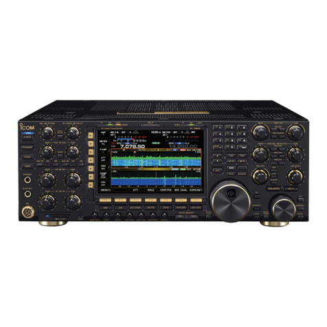
Icom IC-9700 User manual

SERVICE
MANUAL
VHF/UHF ALL MODE TRANSCEIVER
|9700
S-15513XZ- C1
March 2019
www.PH4X.com

INTRODUCTION
This service manual describes the latest technical
information for the IC-9700 VHF/UHF ALL MODE
TRANSCEIVER at the time of publication.
MODEL
VERSION VERSION
NUMBER
IC-9700
USA #12
EUR #13
ITA #15
TPE #17
KOR #18
EXP #19
To upgrade quality, any electrical or mechanical parts and
internal circuits are subject to change without notice or
obligation.
SERVICE CAUTION
NEVER connect the transceiver to an AC outlet or
to a DC power supply that outputs more than the
specified voltage. This will ruin the transceiver.
DO NOT expose the transceiver to rain, snow or
liquids.
DO NOT reverse the polarity of the DC power cable
when directly connecting to the transceiver.
DO NOT apply an RF signal of more than 20 dBm
(100 mW) to the antenna connector. This could
damage the transceiver’s front-end.
ORDERING PARTS
Be sure to include the following four points when
ordering replacement parts:
1. 10-digit Icom part number
2. Component name
3. Equipment model name and unit name
4. Quantity required
<ORDER EXAMPLE>
1180004430 XC6209F502MR IC-9700 MAIN UNIT 5 pieces
8110011570 3913 U-COVER IC-9700 CHASSIS 1 piece
Addresses are provided on the inside back cover for
your convenience.
REPAIR NOTES
1. Make sure that the problem is internal before
disassembling the transceiver.
2. DO NOT open the transceiver until the transceiver
is disconnected from its power source.
3. DO NOT short any circuits or electronic parts.
An insulated tuning tool MUST be used for all
adjustments.
4. DO NOT keep power ON for a long time when the
transceiver is defective.
5. NEVER directly transmit power into any test
equipment such as Standard Signal Generator or
a Sweep Generator, otherwise the RF power may
damage them.
6. ALWAYS connect a 50 dB to 60 dB attenuator
between the transceiver and such test equipment.
7. READ the instructions of the test equipment
thoroughly before connecting it to the transceiver.
Icom, Icom Inc. and the Icom logo are registered trademarks of Icom Incorporated (Japan) in Japan, the United States, the
United Kingdom, Germany, France, Spain, Russia, Australia, New Zealand, and/or other countries. www.PH4X.com
TABLE OF CONTENTS
SECTION 1 SPECIFICATIONS
SECTION 2 INSIDE VIEWS
SECTION 3 INTERFACE INFORMATION
SECTION 4 ADJUSTMENT PROCEDURE
4 -1 PREPAR ATION ……………………………………………………………………………………… 4-1
4-2 FRONT PANEL OPERATION VERIFICATION…………………………………………………… 4-4
4-3 TRANSMIT ADJUSTMENTS ……………………………………………………………………… 4-5
4-4 REFERENCE ADJUSTMENTS …………………………………………………………………… 4-8
4-5 RECEIVE ADJUSTMENTS ………………………………………………………………………… 4-9
SECTION 5 PARTS LIST
SECTION 6 MECHANICAL PARTS
SECTION 7 BOARD LAYOUTS
SECTION 8 WIRING DIAGRAM
SECTION 9 BLOCK DIAGRAM
SECTION 10 SCHEMATIC DIAGRAM
DISTRIBUTORS ADDRESS
www.PH4X.com

SECTION 1 SPECIFICATIONS
1-1
MGeneral
• Frequency range:
RX/TX
144 MHz band (MHz) 430 MHz band (MHz) 1200 MHz band (MHz)
[USA], [EXP] 144.000000 ~ 148.000000 430.000000 ~ 450.000000 1240.000000 ~ 1300.000000
[EUR]
144.000000 ~ 146.000000
430.000000 ~ 440.000000
[KOR] 1260.000000 ~ 1300.000000
[ITR] 430.000000 ~ 434.000000
435.000000 ~ 438.000000
1240.000000 ~ 1245.000000
1270.000000 ~ 1298.000000
[TPE] 430.000000 ~ 432.000000 1260.000000 ~ 1265.000000
• Operating mode: A1A, A3E, J3E, F1B, F1D, F2D, F3E, F7W
• Number of memory channels: 107 (99 Simplexes+6 Program scan edges+2 Calls)×3 Bands
99 (Satellite memories)
• Power supply voltage: 13.8 V DC ±15%
• Polarity: Negative ground
• Antenna impedance: 50 Ω
• Power consumption: Stand-by
Maximum audio
Transmit (high power)
1.2 A (typical)
Less than 1.8 A
Less than 18 A
• Operating temperature range: −10ºC ~ +60ºC (14ºF ~ 140ºF)
• Frequency stability: ±0.5 ppm (−10ºC ~ +60ºC, 14ºF ~ 140ºF)
• Frequency resolution: Minimum 1 Hz
• Dimensions (projections not included):240 (W)×94 (H)×238 (D) mm (9.4 (W)×3.7 (H)×9.4 (D) inches)
• Weight (approximate):4.7 kg (10 Ib 6 oz)
www.PH4X.com

1-2
MTransmitter
• Output power:
144 MHz band 430 MHz band 1200 MHz band
SSB, CW, FM, RTTY, DV 0.5 ~ 100 W 0.5 ~ 75 W 0.1 ~ 10 W
AM 0.125 ~ 25 W 0.125 ~ 18.75 W 0.025 ~ 2.5 W
DD – – 0.1 ~ 10 W
• Modulation method:
SSB
FM
AM
DV, DD
Digital PSN modulation
Digital Reactance modulation
Digital Low Power modulation
Digital GMSK modulation
• Spurious/Unwanted emissions:
Harmonics
Out-of-band
Less than −63 dB (144 MHz band)
Less than −61.8 dB (430 MHz band)
Less than −53 dB (1200 MHz band)
Less than −60 dB (144/430 MHz bands)
Less than −50 dB (1200 MHz band)
• Carrier suppression: More than 50 dB
• Unwanted sideband suppression: More than 50 dB
• Microphone impedance: 600 Ω
www.PH4X.com

1-3
MReceiver
• Receive systems:
144/430 MHz bands
1200 MHz band
RF direct sampling
Down conversion IF sampling
• Intermediate frequencies (1200 MHz band only):
[USA], [EUR], [EXP]
[ITA]
[TPE]
[KOR]
311 ~ 371 MHz
311 ~ 316 MHz, 341 ~ 369 MHz
331 ~ 336 MHz
331 ~ 371 MHz
• Sensitivity (For all version/PREAMP and IP+ ON):
SSB, CW (Filter shape=SOFT)
AM
FM
DV
DD (1200 MHz band only)
Less than −19 dBμV (0.11 μV) (at 10 dB S/N)
Less than 0 dBμV (1.0 μV) (at 10 dB S/N)
Less than −15 dBμV (0.18 μV) (at 12 dB SINAD)
Less than −9 dBμV (0.35 μV) (at 1% BER (PN9))
Less than +4 dBμV (1.59 μV) (at 1% BER (PN9))
The input signal strength level of this receive sensitivity is measured at the load end (PD).
• Sensitivity (For [EUR], [ITA]/PREAMP and IP+ ON):
SSB, CW (BW=2.4 kHz, Filter shape=SOFT)
AM (BW=4 kHz, 60% modulation)
FM (BW=7 kHz, 60% modulation)
Less than −6 dBμV emf (at 12 dB SINAD)
Less than 0 dBμV emf (at 12 dB SINAD)
Less than −6 dBμV emf (at 12 dB SINAD)
• Selectivity:
SSB (BW=2.4 kHz, Filter shape=SHARP)
CW, RTTY (BW=500 Hz)
AM (BW=6 kHz)
FM (BW=15 kHz)
DV (Channel spacing=12.5 kHz)
DD (Channel spacing=300 kHz)
More than 2.4 kHz/–3 dB, Less than 3.6 kHz/–60 dB
More than 500 Hz/–3 dB, Less than 700 Hz/–60 dB
More than 6.0 kHz/–3 dB, Less than 15 kHz/–60 dB
More than 12.0 kHz/–6 dB, Less than 20 kHz/–60 dB
Less than –50 dB
Less than –40 dB
• Spurious and image rejection ratio:
SSB, CW
AM, FM, DV
DD
More than 70 dB (144/430 MHz bands)
More than 50 dB (1200 MHz band)
More than 60 dB (144/430 MHz bands)
More than 50 dB (1200 MHz band)
• Audio output power: More than 2.0 W ( at 10% distortion into an 8 Ω load , at the
1 kHz reference)
• Audio output impedance: 8 Ω
• RIT variable range: ±9.999 kHz
• ANF attenuation: More than 30 dB (at 1 kHz single tone)
• MNF attenuation: More than 70 dB
• NR attenuation: More than 6 dB (Internal noise suppression ratio in the SSB
mode)
www.PH4X.com

SECTION 2 INSIDE VIEWS
2-1
CLOCK GENERATOR
(IC8701)
ADC
(IC7501)
[DATA] (J2901)
[ACC] (J2911)
[LAN] (J1901)
[REF IN 10MHz]
(W131:CHASSIS)
J9151
CPLD
(IC301)
FLASH ROM
(IC331)
FPGA
(IC7601)
DAC
(IC7201)
MAIN-CPU
(IC101)
LVDS DRIVER
(IC8693)
CLOCK DIVISION IC
(IC8692)
Inside the shielded case.
SUB-CPU
(IC311)
DV-DSP
(IC502)
USB HUB
(IC1601)
USB CODEC
(IC1531)
J9501
J2881
SDRAM
(IC102)
DAC
(IC2001)
APC AMPLIFIER
(IC2541)
ALC AMPLIFIER
(IC2501)
J9401
J9101
J9301
J9201
J3071
J3091
J3081
J3021
J3111
J3101
J9001
J8661
[USB] (J1601)
[REMOTE]/[KEY]
(J2891)
[EX-SP MAIN]/
[EX-SP SUB]
(J2891)
REFERENCE
OSCILLATOR
(X1)
Inside the shielded case.
+5 V REGULATOR
(IC1221)
• MAIN UNIT (TOP VIEW)
MAIN UNIT
www.PH4X.com

2-2
POWER AMPLIFIER
(Q301)
POWER AMPLIFIER
(Q301)
PREAMPLIFIER
(IC1161)
PREAMPLIFIER
(IC1161)
RF AMPLIFIER
(Q1181)
PREAMPLIFIER
(IC321)
TX/RX SWITCH
(RL51)
POWER AMPLIFIER
(Q81)
SAW FILTER
(FI321)
PRE DRIVE
(IC141)
DRIVER
(Q101)
YGR AMPLIFIER
(IC191)
Inside the shielded case.
PLL IC
(IC271)
Inside the shielded case.
J431
J301
J501
J251 J101
J1201 J6
J1 J41
J61
IF AMPLIFIER
(IC421)
IF FILTER
(FI431)
TX/RX SWITCH
(RL401)
DRIVER
(Q201)
DRIVER
(Q201)
PER DRIVE
(IC101)
PER DRIVE
(IC101)
J1
J101
J1201
[144MHz ANT]
(J1: CHASSIS UNIT)
[430MHz ANT]
(J2: CHASSIS UNIT)
[1200MHz ANT]
(J3: CHASSIS UNIT)
[DC13.8V]
(W51: CHASSIS UNIT)
SAW FILTER
(FI1191)
• PA-A/PA-B/PA-C UNIT (TOP VIEW)
PA-C UNIT PA-A UNIT
PA-B UNIT
www.PH4X.com

2-3
TOUCH SCREEN
CONTROLLER
(IC152)
FRONT CPU
(IC501)
MAIN DIAL
(EP1)
LCD DRIVER
(IC101)
Inside the
shielded case.
J401
J1
J51
J451
J421
J2
J2
J1
J61
J71
J201
J101
J1
J601
• FRONT UNIT (BOTTOM VIEW: DISPLAY/VR-A/VR-B/RIT/PHONE/MIC/SD UNIT)
• DISPLAY UNIT (TOP VIEW)
RIT UNIT
DISPLAY UNIT
PHONE UNIT
VR-B UNIT
VR-A UNIT
MIC UNIT
SD UNIT
[EXIT] (S13)
[QUICK] (S12)[M.SCOPE] (S11)
[MENU] (S9)
[NR] (S8)
[NB] (S7)
[NOTCH] (S6)
[P.AMP/ATT] (S5)
[VOX/BK-IN] (S4)
[CALL/DR] (S3)
[TRANSMIT] (S2)
[FUNCTION] (S10)
[POWER] (S1)
[MPAD] (S25)
[TONE/RX>CS] (S24)
[SCAN] (S23)
[V/M] (S22)
[A/B] (S21)
[SPLIT] (S20)
[RIT] (S17)
[PBT] (S19)
[XFC] (S14)
[AFC/AUTO TUNE]
(S15)
[SPEECH/LOCK] (S16)
[kHz/M-ch] (S18)
www.PH4X.com

SECTION 3 INTERFACE INFORMATION
3-1
SECTION 3 INTERFACE INFORMATION
● FRONT panel
[PHONES]
• 3.5 mm (⅛ in) (d)
[MIC]
[PHONES]
Main band audio
Sub band audio
GND
3.5 (d) mm (⅛in)
• Output impedance: 8 ~ 16 Ω
• Output level: More than 5 mW into an 8 Ω
load.
[MIC]
qMicrophone input
w+8 V DC output
eFrequency up/down
rSquelch line output
tPTT
yGND (PTT ground)
iAF output
uGND
(Microphone ground)
PIN No. DESCRIPTION
q
Microphone input
NOTE: This pin outputs 8 V DC power supply for
the Icom microphone.
w+8 V DC output (Maximum 10 mA)
eFrequency up/down
External keypad*input
rGrounded when squelch opens.
tPTT
yPTT/External keypad*ground
uMicrophone ground
iAF output [EXT-SP MAIN]/[EXT-SP SUB]
(varies with the AF control.)
*External keypad
PIN e
PIN y
1.5 kΩ
±5%
1.5 kΩ
±5%
2.2 kΩ
±5%
4.7 kΩ
±5%
S1S2S3S4
1
2
345
6
7
8
MIC
External keypad
Front panel
view
[MIC]
connector
www.PH4X.com

3-2
● REAR panel (1)
[REF IN 10MHz]
• SMA connector: 50 Ω
[REMOTE]
• 3.5 mm (⅛ in) (d)
[DC 13.8 V]
[KEY]
• 3.5 mm (⅛ in) (d)
[EXT-SP MAIN]/[EXT-SP SUB]
• 3.5 mm (⅛ in) (d)
[DATA]
• 2.5 mm (d)
[DC 13.8 V]
Rear panel view
+
−
• Input voltage: 13.8 V DC ±15%
[REMOTE]
3.5 mm (⅛ in) (d)
GND
I/O
[DATA]
2.5 mm (¹⁄10 in) (d)
GND TxD
RxD
• Data communication: RS-232C compliant
[REF IN 10MHz]
SMA connector
• Input frequency: 10 MHz
• Impedance: 50 Ω (unbalanced)
• Input level: –10 dBm (approximate)
[KEY]
Connects to a Paddle key or Straight key.
• Paddle key
3.5 mm (⅛in) (d)
Dot
Com
Dash
• Straight key
3.5 mm (⅛in) (d)
+
−
[EXT-SP MAIN]/[EXT-SP SUB]
Audio −
Audio +
3.5 mm (⅛ in) (d)
• Output impedance: 4~8 Ω
• Output level: More than 2.0 W at 10%
distortion into an 8 Ω load.
www.PH4X.com

3-3
● REAR panel (2)
[ACC]
• 8-pin
[ACC]
ACC PIN
No.
PIN
NAME DESCRIPTION SPECIFICATIONS
1
2
3
4 5
6 7
8
8-pin
Rear panel
view
1RTTY Controls RTTY keying.
High level: More than 2.4 V
Low level: Less than 0.6 V
Current flow: Maximum 2 mA
2GND Connects to ground. –
3SEND*1Input/output pin.
An external unit controls
the transceiver.
When this pin goes to
ground, the transceiver
transmits.
Input voltage (RX): 2.0 ~ 20.0 V
Input voltage (TX): −0.5 ~ +0.8 V
Current flow: Maximum 20 mA
The pin goes low
when the transceiver
transmits.
Output voltage (TX):
Less than 0.1 V
Current flow: Maximum 200 mA
4MOD Modulator input.
Connects to the internal modulator circuit.
Input impedance: 10 kΩ
Output level: Approx. 100 mV rms*2
5AF/IF
(IF=12 kHz)*3
Fixed AF detector or receive IF (12 kHz)
signal output.
Output impedance: 4.7 kΩ
Output level: 100~300 mV rms*4
6 SQL S
Squelch output.
This pin goes to ground when the
squelch opens (TX/RX indicator lights
green).
SQL open: Less than 0.3 V/5 mA
SQL closed: More than 6.0 V/100 μA
713.8 V 13.8 V output when power is ON. Output current: Maximum 1 A
8ALC ALC voltage input. Input level: −4 ~ 0 V
Input impedance: More than 10 kΩ
*1 When the SEND terminal controls an inductive load, such
as a relay, a counter-electromotive force can malfunction
or damage the transceiver.
To prevent this, we recommend adding a switching diode,
such as an 1SS133, on the load side of the circuit to
absorb the counter-electromotive force.
When the diode is added, a delay in relay switching may
occur.
Be sure to check its switching action before operating.
(Example) ACC socket
To a non-Icom
linear amplifier
Relay
Switching diode
eSEND
u13.8 V
*2The MOD input level is adjustable in the MENU.
100 mV rms is at 50% as the default.
MENU » SET > Connectors > ACC MOD Level
*3The AF/IF (IF=12 kHz) settings are selectable to output a
12 kHz IF signal in the MENU. In that case.
MENU » SET > Connectors > ACC Output Select
*4The AF/IF (IF=12 kHz) output level is adjustable in the
MENU.
Approximately 200 mV rms is at the 50% as the default.
MENU » SET > Connectors > ACC IF Output Level
www.PH4X.com

4-1
SECTION 4 ADJUSTMENT PROCEDURE
4-1 PREPARATION
■REQUIRED EQUIPMENT
EQUIPMENT GRADE AND RANGE EQUIPMENT GRADE AND RANGE
DC power supply Output voltage: 13.8 V±15%
Current capacity: 25 A or more Shunt plug Modified 3.5 mm (⅛ inch) monaural plug.
(See the illustration shown on page 4-2.)
RF power meter
(50 Ω terminated)
Measuring range: 1 ~ 120 W
Frequency range: 0.1 ~ 1500 MHz
SWR: Less than 1.2 : 1
Standard signal
generator (SSG)
Frequency range: 0.1 ~ 1500 MHz
Output level: −20 to 90 dBμ
(−127 to −17 dBm)
10 MHz reference
signal generator Frequency accuracy: ±5×10⁻⁴ ppm or less Audio generator
(AG)
Frequency range: 300 ~ 3000 Hz
Output level: 1 ~ 500 mV
AC millivoltmeter Measuring range: 10 mV to 10 V Dummy Loads Impedance: 100 Ω
Capacity: More than 120 W
■CONNECTIONS
●Connections on the Front panel
[MIC]
Audio
generator
[MIC]
MIC
MICE
AC
millivoltmeter
●Connections on the Rear panel
RF POWER METER
(120 W/50 Ω)
STANDARD SIGNAL GENERATOR
(0.1~1500 MHz)
NEVER TRANSMIT while the SSG is connected.
DUMMY LOAD
(100 Ω/120 W)
Used for SWR meter adjustments. (VSWR 2:1)
to [144MHz ANT] to [430MHz ANT]
to [REF IN 10MHz]
to [1200MHz ANT]
10 MHz REFERENCE
SIGNAL GENERATOR
(−10 dBm)
to [DC 13.8V]
DC POWER SUPPLY
(13.8 V/25 A)
Red
Black
www.PH4X.com

4-2
■ENTERING THE ADJUST MODE
1. Turn OFF the power.
2. Connect the shunt plug to the [REMOTE] connector on
the rear panel. (See below)
to [REMOTE]
3.5 mm (⅛ inch)
monaural plug
(Shunt)
3. While holding down both [MENU] and [FUNCTION], turn
ON the transceiver power to enter the adjust mode.
[POWER]
[MENU] [FUNCTION]
4. The adjust mode main menu is displayed.
■KEY ASSIGNMENTS FOR THE ADJUST MODE
• Touch [▼] to select the next adjustment item, touch [▲] to
select the previous adjustment item.
• Rotate [MAIN DIAL] to set or modify the adjustment value.
• Touch [SET] to store the adjusted value, and select the
next adjustment item.
• Push [EXIT] to return to the previous screen.
Stores the adjusted value.
Selects the next adjustment item.
Selects the previous adjustment item.
Adjustment item name
Adjustment value
[MAIN DIAL][EXIT]
www.PH4X.com

4-3
■ENTERING THE ADJUST MODE
• FRONT PANEL OPERATION VERIFICATION MENU
• MAIN MENU
• TX/ID ADJUST MENU
• REF ADJUST MENU • RX ADJUST MENU
Enter the FRONT panel operation verification menu.
Enter the TX/ID adjust menu.
Enter the REF adjust menu.
Enter the RX adjust menu.
Starts the 1.2 GHz band
adjustment.
Starts the 430 MHz band
adjustment.
Starts the VHF band adjustment.
Starts idling current adjustment.
Starts the 1.2 GHz B
band adjustment.
Starts the 1.2 GHz A band
adjustment.
Starts the 430 MHz band adjustment.
Starts the VHF band adjustment.
Starts the touch screen
calibration.
Starts the LED and LCD verification.
Starts the volume verification.
Starts the key verification.
Starts the reference frequency adjustment.
www.PH4X.com

4-4
4-2 FRONT PANEL OPERATION VERIFICATION
1. Touch [FRONT] on the main adjustment menu screen.
2. Touch [KEYch] to enter to the key operation verification mode.
3. Follow the instructions displayed on the screen, and push the corresponding key.
4. Follow the instructions displayed on the screen, and turn the corresponding dial and sensor.
5. Follow the instructions displayed on the screen, and insert/remove the SD card.
6. Follow the instruction displayed on the screen, and verify the corresponding LED is lit.
7. Push the [TONE (RX→CS)] key, and verify the LCD screen changes in order of red, green, blue, minimum, and
maximum backlight brightness.
8. Push the [TONE (RX→CS)] key to start the touch screen calibration, and touch the dot in order of the instructions
displayed on the screen.
9. Push [EXIT] to return to the main adjustment menu screen.
www.PH4X.com

4-5
4-3 TRANSMIT ADJUSTMENTS
Touch [TX/ID] on the main adjustment menu screen.
ADJUSTMENT ADJUSTMENT ITEM
DISPLAY SETTING CONDITION OPERATION
IDLING
-Preparation-
1 – – Touch [ID] to enter to the TX idling
current adjustment mode.
2 VDL IDL Set • Receiving Touch [SET].
-Adjustment- 3VHF ID SET • Automatically transmitted. Touch [SET].
(Two beeps sound after adjustment
of each item is completed.)
4VHF FIDV
5VHF DIDV
6UHF ID SET
7UHF FIDV
8UHF DIDV
9 1.2G ID SET
10 1.2G FIDV
11 1.2G DIDV
VHF TX OUTPUT
POWER
-Preparation-
1 – • Connect the RF power meter to
the [144MHz ANT] connector.
• Connect the audio generator to
[MIC] connector, and set it to:
Frequency: 1.5 kHz
Waveform: Sine wave
Level: 30 mV rms
Touch [VHF] to enter to the VHF
output power adjustment mode.
-Adjustment- 2 TX POWER VHF SET • Receiving Touch [SET].
3 TX Total VHF Gain • Automatically transmitted. Set to 50 W by [MAIN DIAL], then
touch [SET].
(Two beeps sound after adjustment
of the item is completed.)
4 POWER VHF2 MIN Set to 0.5 W by [MAIN DIAL], then
touch [SET].
(Two beeps sound after adjustment
of the item is completed.)
5 POWER VHF2 1% Set to 1 W by [MAIN DIAL], then
touch [SET].
(Two beeps sound after adjustment
of the item is completed.)
6 POWER VHF2 10% Set to 10 W by [MAIN DIAL], then
touch [SET].
(Two beeps sound after adjustment
of the item is completed.)
7 POWER VHF2 50% Set to 50 W by [MAIN DIAL], then
touch [SET].
(Two beeps sound after adjustment
of the item is completed.)
8 POWER VHF2 100% Set to 100 W by [MAIN DIAL], then
touch [SET].
(Two beeps sound after adjustment
of the item is completed.)
VHF TX
BALANCE
-Adjustment-
1 POWER VHF Balance SET • Receiving Touch [SET].
2 POWER VHF1 100% • Automatically transmitted. Set to 100 W by [MAIN DIAL], then
touch [SET].
(Two beeps sound after adjustment
of each item is completed.)
3 POWER VHF3 100%
VHF AM CARRIER
POWER R ATE
-Adjustment-
1 POWER AM Ratio VHF • Receiving Touch [SET].
2 • Automatically transmitted. Set to 25 W by [MAIN DIAL], then
touch [SET].
(Two beeps sound after adjustment
of the item is completed.)
VHF ALC
-Adjustment-
1ALC VHF • Automatically transmitted. Touch [SET].
(Two beeps sound after adjustment
of the item is completed.)
VHF DRIVE GAIN
-Adjustment-
1 DRIVE VHF • Automatically transmitted. Touch [SET].
(Two beeps sound after adjustment
of the item is completed.)
4-5
www.PH4X.com

4-6
4-3 TRANSMIT ADJUSTMENTS (CONTINUED)
ADJUSTMENT ADJUSTMENT ITEM
DISPLAY SETTING CONDITION OPERATION
VHF Id APC
-Adjustment-
1ID-APC • Receiving Touch [SET].
2 • Automatically transmitted. Touch [SET].
(Two beeps sound after adjustment
of the item is completed.)
VHF SWR METER
-Preparation-
If a 100 Ω dummy load (or a dummy load with a VSWR of 2:1) is unavailable, skip the SWR meter adjustment.
1 – • Connect the 100 Ω dummy load
to [144MHz ANT] connector.
–
2SWR2 (VHF) • Automatically transmitted. Touch [SET].
(Two beeps sound after adjustment
of the item is completed.)
UHF TX OUTPUT
POWER
-Preparation-
1 – • Connect the RF power meter to
the [430MHz ANT] connector.
• Connect the audio generator to
[MIC] connector, and set it to:
Frequency: 1.5 kHz
Waveform: Sine wave
Level: 30 mV rms
Touch [UHF] to enter to the UHF
output power adjustment mode.
-Adjustment- 2 TX POWER UHF SET • Receiving Touch [SET].
3 TX Total UHF Gain • Automatically transmitted. Set to 37.5 W by [MAIN DIAL], then
touch [SET].
(Two beeps sound after adjustment
of the item is completed.)
4 POWER UHF2 MIN Set to 0.5 W by [MAIN DIAL], then
touch [SET].
(Two beeps sound after adjustment
of the item is completed.)
5 POWER UHF2 1% Set to 0.75 W by [MAIN DIAL], then
touch [SET].
(Two beeps sound after adjustment
of the item is completed.)
6 POWER UHF2 10% Set to 7.5 W by [MAIN DIAL], then
touch [SET].
(Two beeps sound after adjustment
of the item is completed.)
7 POWER UHF2 50% Set to 37.5 W by [MAIN DIAL], then
touch [SET].
(Two beeps sound after adjustment
of the item is completed.)
8 POWER UHF2 100% Set to 75 W by [MAIN DIAL], then
touch [SET].
(Two beeps sound after adjustment
of the item is completed.)
UHF TX BALANCE
-Adjustment-
1 POWER UHF Balance SET • Receiving Touch [SET].
2 POWER UHF1 100% • Automatically transmitted. Set to 75 W by [MAIN DIAL], then
touch [SET].
(Two beeps sound after adjustment
of each item is completed.)
3 POWER UHF3 100%
4 POWER UHF4 100%
UHF AM CARRIER
POWER R ATE
-Adjustment-
1 POWER AM Ratio UHF • Receiving Touch [SET].
2 • Automatically transmitted. Set to 18.75 W by [MAIN DIAL], then
touch [SET].
(Two beeps sound after adjustment
of the item is completed.)
UHF ALC
-Adjustment-
1ALC UHF • Automatically transmitted. Touch [SET].
(Two beeps sound after adjustment
of the item is completed.)
UHF DRIVE GAIN
-Adjustment-
1DRIVE UHF • Automatically transmitted. Touch [SET].
(Two beeps sound after adjustment
of the item is completed.)
UHF SWR METER
-Preparation-
If a 100 Ω dummy load (or a dummy load with a VSWR of 2:1) is unavailable, skip the SWR meter adjustment.
1 – • Connect the 100 Ω dummy load
to [430MHz ANT] connector.
–
2SWR2 (UHF) • Automatically transmitted. Touch [SET].
(Two beeps sound after adjustment
of the item is completed.)
www.PH4X.com

4-7
4-3 TRANSMIT ADJUSTMENTS (CONTINUED)
ADJUSTMENT ADJUSTMENT ITEM
DISPLAY SETTING CONDITION OPERATION
1.2GHz TX
OUTPUT POWER
-Preparation-
1 – • Connect the RF power meter to
the [1200MHz ANT] connector.
• Connect the audio generator to
[MIC] connector, and set it to:
Frequency: 1.5 kHz
Waveform: Sine wave
Level: 30 mV rms
Touch [1.2G] to enter to the 1.2GHz
output power adjustment mode.
-Adjustment- 2 TX POWER 1.2G SET • Receiving Touch [SET].
3 TX Total 1.2G Gain • Automatically transmitted. Set to 5 W by [MAIN DIAL], then
touch [SET].
(Two beeps sound after adjustment
of the item is completed.)
4 POWER 1.2G3 MIN Set to 0.1 W by [MAIN DIAL], then
touch [SET].
(Two beeps sound after adjustment
of each item is completed.)
5 POWER 1.2G3 1%
6 POWER 1.2G3 10% Set to 1 W by [MAIN DIAL], then
touch [SET].
(Two beeps sound after adjustment
of the item is completed.)
7 POWER 1.2G3 50% Set to 5 W by [MAIN DIAL], then
touch [SET].
(Two beeps sound after adjustment
of the item is completed.)
8 POWER 1.2G3 100% Set to 10 W by [MAIN DIAL], then
touch [SET].
(Two beeps sound after adjustment
of the item is completed.)
1.2GHz TX
BALANCE
-Adjustment-
1 POWER 1.2G Balance SET • Receiving Touch [SET].
2 POWER 1.2G2 100% • Automatically transmitted. Set to 10 W by [MAIN DIAL], then
touch [SET].
(Two beeps sound after adjustment
of each item is completed.)
3 POWER 1.2G4 100%
4 POWER 1.2G1 100%
1.2GHz AM
CARRIER POWER
RATE
-Adjustment-
1 POWER AM Ratio 1.2G • Receiving Touch [SET].
2 • Automatically transmitted. Set to 2.5 W by [MAIN DIAL], then
touch [SET].
(Two beeps sound after adjustment
of the item is completed.)
1.2GHz ALC
-Adjustment-
1 ALC 1.2G • Automatically transmitted. Touch [SET].
(Two beeps sound after adjustment
of the item is completed.)
1.2GHz DRIVE
GAIN
-Adjustment-
1 DRIVE 1.2G • Automatically transmitted. Touch [SET].
(Two beeps sound after adjustment
of the item is completed.)
1.2GHz SWR
METER
-Preparation-
If a 100 Ω dummy load (or a dummy load with a VSWR of 2:1) is unavailable, skip the SWR meter adjustment.
1 – • Connect the 100 Ω dummy load
to [1200MHz ANT] connector.
–
2 SWR2 (1.2G) • Automatically transmitted. Touch [SET].
(Two beeps sound after adjustment
of the item is completed.)
• After the adjustment, the transceiver shows the TX/ID adjustment menu.
• Push [EXIT] to return to the main adjustment menu screen.
www.PH4X.com

4-8
4-4 REFERENCE ADJUSTMENTS
Touch [REF] on the main adjustment menu screen.
ADJUSTMENT ADJUSTMENT ITEM
DISPLAY SETTING CONDITION OPERATION
REFERENCE
FREQUENCY
-Preparation-
1 – • Connect the 10 MHz reference
signal generator to the [REF IN
10 MHz] connector.
Touch [REF] to enter to the
reference frequency adjustment
mode.
-Adjustment- 2 REF OSC 1 • Set the 10 MHz reference signal
generator to:
Level: −10 dBm
• Receiving
Touch [SET].
(Two beeps sound after adjustment
of the item is completed.)
• After the adjustment, the transceiver shows the "REF OSC 2" adjustment item.
• Push [EXIT] twice to return to the main adjustment menu screen.
www.PH4X.com
Other manuals for IC-9700
5
Table of contents
Other Icom Transceiver manuals

Icom
Icom IC-F5010 series User manual

Icom
Icom IC-7300 Installation instructions

Icom
Icom ic-f1000d series User manual

Icom
Icom IC-F51 User manual

Icom
Icom IC-40Jr User manual

Icom
Icom IC-F8101 User manual

Icom
Icom IC-725 User manual

Icom
Icom IC-281H User manual

Icom
Icom IC-H16T MKII User manual

Icom
Icom IC-F3400DP Series User manual
Popular Transceiver manuals by other brands

Alinco
Alinco DJ-AXD4 user manual

Sitex
Sitex Metadata MDA-5 Installation & operation manual

BLACKHAWK!
BLACKHAWK! USB510W quick start guide

Pocket Wizard
Pocket Wizard MiniTT1 Guide rapide

Uni-Com
Uni-Com Mini UTP Transceiver ETP-20028T installation manual

Delta
Delta 1x9 Bi-Directional Transceiver Module... Specification sheet