Icom IC-M504 User manual

INSTRUCTION MANUAL
iM504
VHF MARINE TRANSCEIVER

i
FOREWORD
Thank you for purchasing this Icom product. The IC-M504
vhf marine transceiver is designed and built with Icom’s
state of the art technology and craftsmanship. With proper
care, this product should provide you with years of trouble-
free operation.
We want to take a couple of moments of your time to thank
you for making the IC-M504 your radio of choice, and hope
you agree with Icom’s philosophy of “technology first.” Many
hours of research and development went into the design of
your IC-M504.
DFEATURES
❍Simple operation with large keys
❍Easy to hear speaker
❍Built-in DSC meets ITU Class D requirement
❍Rugged waterproof construction
❍Optional COMMANDMIC (HM-162/HM-157)
are available
❍Easy to make individual DSC calls using Icom's
MA-500TR Class B AIS Transponder
IMPORTANT
READ ALL INSTRUCTIONS carefully and completely
before using the transceiver.
SAVE THIS INSTRUCTION MANUAL — This in-
struction manual contains important operating instructions
for the IC-M504.
EXPLICIT DEFINITIONS
WORD DEFINITION
RWARNING! Personal injury, fire hazard or electric
shock may occur.
CAUTION Equipment damage may occur.
NOTE
If disregarded, inconvenience only. No risk
of personal injury, fire or electric shock.
CLEAN THE TRANSCEIVER AND MICROPHONE
THOROUGHLY WITH FRESH WATER after exposure to
water including salt, otherwise, the keys and switch may
become inoperable due to salt crystallization.

IN CASE OF EMERGENCY
If your vessel requires assistance, contact other vessels and
the Coast Guard by sending a Distress call on Channel 16.
Or, transmit your Distress call using digital selective calling
on Channel 70.
NOTE
A WARNING STICKER is supplied with the transceiver.
To comply with FCC regulations, this sticker must be affixed
in such a location as to be readily seen from the operating
controls of the radio as in the diagram below. Make sure the
chosen location is clean and dry before applying the sticker.
EXAMPLE
WARNING
STICKER
USING CHANNEL 16
DISTRESS CALL PROCEDURE
1. “MAYDAY MAYDAY MAYDAY.”
2. “THIS IS ...............” (name of vessel).
3. Say your call sign or other indication of the vessel (AND
9-digit DSC ID if you have one).
4. “LOCATED AT ...............” (your position).
5. State the nature of the distress and assistance required.
6. Give any other information which might facilitate the
rescue.
USING DIGITAL SELECTIVE CALLING (Ch 70)
DISTRESS CALL PROCEDURE
1. While lifting up the key cover, push and hold [DIS-
TRESS] for 5 sec. until you hear 5 short beeps change
to one long beep.
2. Wait for an acknowledgment on Channel 70 from a
coast station.
•Aftertheacknowledgementisreceived,Channel16isauto-
matically selected.
3. Push and hold [PTT], then transmit the appropriate in-
formation as listed above.
ii

iii
RADIO OPERATOR WARNING
WARNING
Icom requires the radio operator to meet the
FCC Requirements for Radio Frequency Expo-
sure. An omnidirectional antenna with gain not
greater than 9 dBi must be mounted a mini-
mum of 5 meters (measured from the lowest
point of the antenna) vertically above the main
deck and all possible personnel. This is the minimum safe
separation distance estimated to meet all RF exposure com-
pliance requirements. This 5 meter distance is based on the
FCC Safe Maximum Permissible Exposure (MPE) distance
of 3 meters added to the height of an adult (2 meters) and is
appropriate for all vessels.
For watercraft without suitable structures, the antenna must
be mounted so as to maintain a minimum of 1 meter verti-
cally between the antenna, (measured from the lowest point
of the antenna), to the heads of all persons AND all persons
must stay outside of the 3 meter MPE radius.
Do not transmit with radio and antenna when persons are
within the MPE radius of the antenna, unless such persons
(such as driver or radio operator) are shielded from antenna
field by a grounded metallic barrier. The MPE Radius is the
minimum distance from the antenna axis that person should
maintain in order to avoid RF exposure higher than the al-
lowable MPE level set by FCC.
FAILURE TO OBSERVE THESE LIMITS MAY ALLOW
THOSE WITHIN THE MPE RADIUS TO EXPERIENCE RF
RADIATION ABSORPTION WHICH EXCEEDS THE FCC
MAXIMUM PERMISSIBLE EXPOSURE (MPE) LIMIT.
IT IS THE RESPONSIBILITY OF THE RADIO OPERATOR
TO ENSURE THAT THE MAXIMUM PERMISSIBLE EXPO-
SURE LIMITS ARE OBSERVED AT ALL TIMES DURING
RADIO TRANSMISSION. THE RADIO OPERATOR IS TO
ENSURE THAT NO BYSTANDERS COME WITHIN THE
RADIUS OF THE MAXIMUM PERMISSIBLE EXPOSURE
LIMITS.
Determining MPE Radius
THE MAXIMUM PERMISSIBLE EXPOSURE (MPE) RA-
DIUS HAS BEEN ESTIMATED TO BE A RADIUS OF
ABOUT 3M PER OET BULLETIN 65 OF THE FCC.
THIS ESTIMATE IS MADE ASSUMING THE MAXIMUM
POWER OF THE RADIO AND ANTENNAS WITH A MAXI-
MUM GAIN OF 9dBi ARE USED FOR A SHIP MOUNTED
SYSTEM.

iv
TABLE OF CONTENTS 1
2
3
4
5
6
7
8
9
10
11
12
13
14
15
16
FOREWORD ..................................................................................... i
IMPORTANT...................................................................................... i
EXPLICIT DEFINITIONS................................................................... i
IN CASE OF EMERGENCY............................................................. ii
NOTE................................................................................................ ii
RADIO OPERATOR WARNING ...................................................... iii
TABLE OF CONTENTS................................................................... iv
PRECAUTIONS................................................................................ v
1 OPERATING RULES ..................................................................1
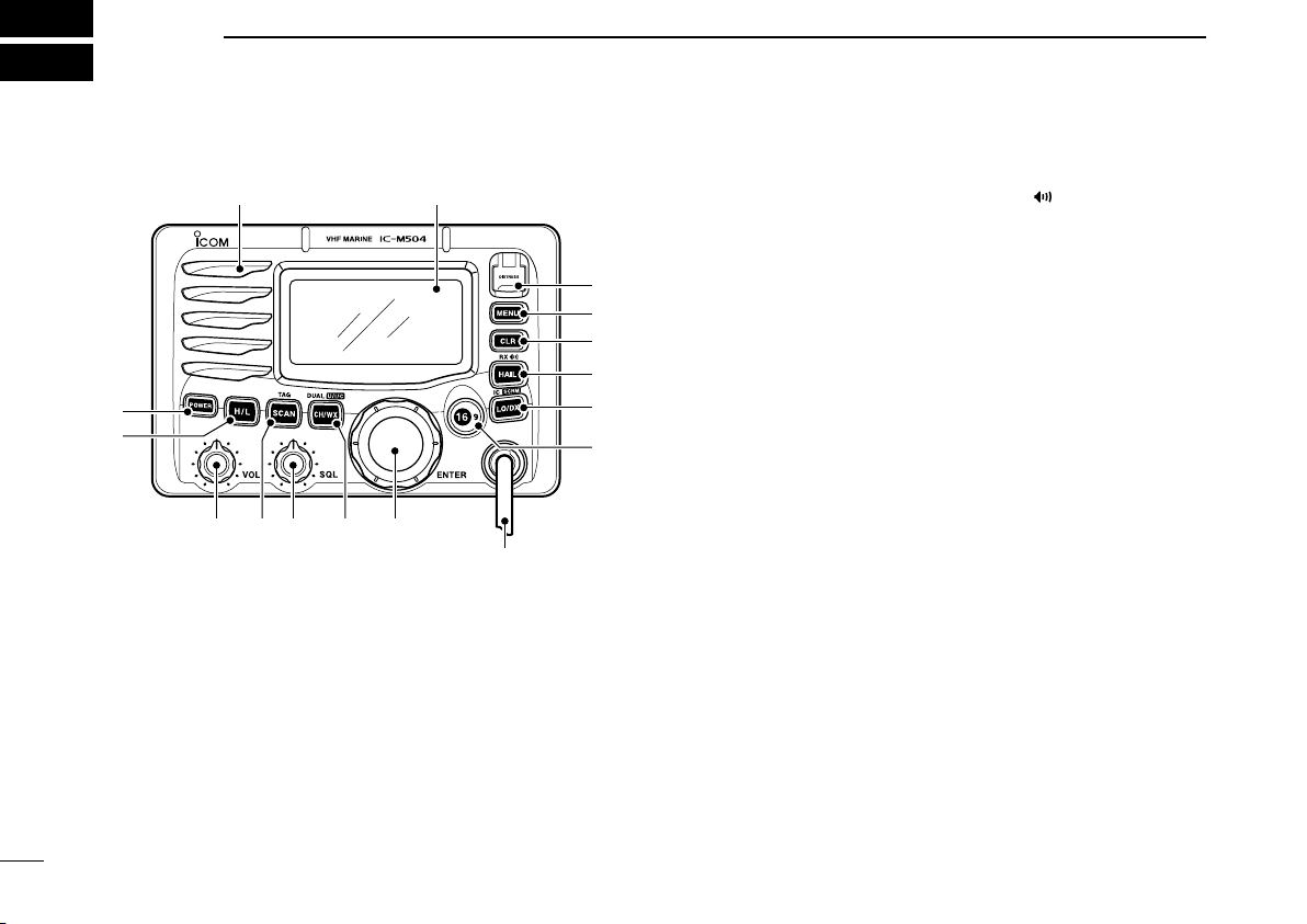
2 PANEL DESCRIPTION ...........................................................2−5
■ Front panel ...............................................................................2
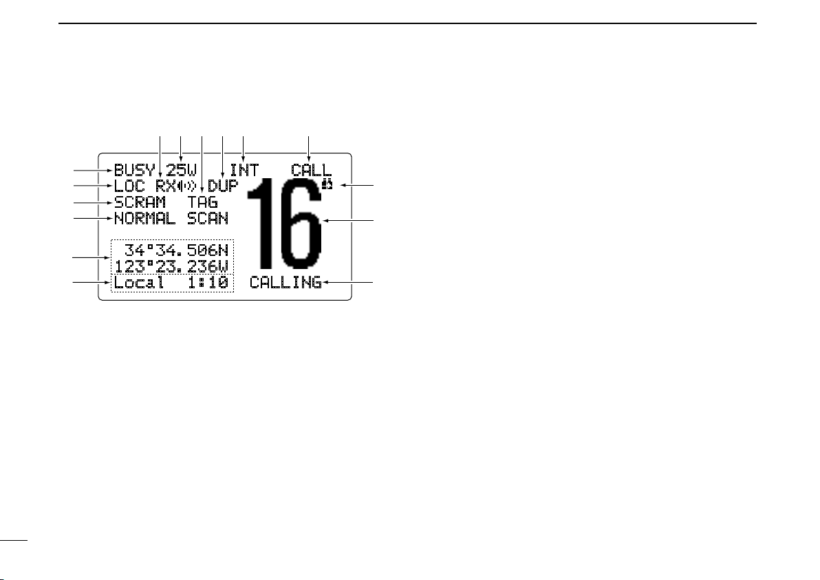
■ Function display .......................................................................4
■ Microphone ..............................................................................5
3 BASIC OPERATION .............................................................6−11
■ Channel selection.....................................................................6
■ Receiving and transmitting.......................................................8
■ Call channel programming .......................................................9
■ Channel comments ................................................................10
■ Microphone Lock function ......................................................10
■ Display backlight ....................................................................10
■ Optional voice scrambler operation........................................11
4 SCAN OPERATION ............................................................12−13
■ Scan types............................................................................. 12
■ Setting TAG channels ............................................................13
■ Starting a scan.......................................................................13
5 DUALWATCH/TRI-WATCH .......................................................14
■ Description.............................................................................14
■ Operation............................................................................... 14
6 DSC OPERATION...............................................................15−49
■ MMSI code programming ...................................................... 15
■ MMSI code check ..................................................................16
■ DSC address ID.....................................................................17
■
Position and time programming ........................................................ 21
■ Position and time indication ...................................................22
■ GPS information indication ....................................................22
■ Distress call ...........................................................................23
■ Transmitting DSC calls...........................................................26
■ Receiving DSC calls ..............................................................41
■ Received messages ..............................................................45
■ DSC Set mode.......................................................................47
7 OTHER FUNCTIONS ..........................................................50−54
■ Intercom operation.................................................................50
■ RX Speaker function..............................................................51
■ Hailer operation .....................................................................52
■ Automatic foghorn function ....................................................53
8 SET MODE..........................................................................55−57
■ Set mode programming .........................................................55
■ Set mode items......................................................................55
9 CONNECTIONS AND MAINTENANCE..............................58−66
■ Connections...........................................................................58
■ Fuse replacement..................................................................59
■ Supplied accessories.............................................................59
■ Antenna .................................................................................59
■ Mounting the transceiver .......................................................60
■ MB-75 installation ..................................................................61
■ UT-112 installation .................................................................62
■ HM-162/HM-157 installation ..................................................63
10 TROUBLESHOOTING ..............................................................67
11 SPECIFICATIONS AND OPTIONS.....................................68−69
■ Specifications.........................................................................68
■ Options ..................................................................................69
12 CHANNEL LIST ........................................................................70
13 TEMPLATE ...............................................................................71
14 FCC INFORMATION .................................................................73

v
PRECAUTIONS
RWARNING! NEVER
connect the transceiver to an AC
outlet. This may pose a fire hazard or result in an electric shock.
CAUTION: Changes or modifications to this device, not
expressly approved by Icom Inc., could void your authority to
operate this device under FCC regulations.
RWARNING! NEVER connect the transceiver to a
power source of more than 16 V DC or use reverse polarity.
This will ruin the transceiver.
RWARNING! NEVER cut the DC power cable between
the DC plug at the back of the transceiver and fuse holder. If
an incorrect connection is made after cutting, the transceiver
may be damaged.
CAUTION: NEVER
place the transceiver where normal
operation of the vessel may be hindered or where it could
cause bodily injury.
CAUTION:
KEEP the transceiver and microphone at
least 3.3 ft (1 m) away from the vessel’s magnetic navigation
compass.
DO NOT use or place the transceiver in areas with tem-
peratures below –4°F (–20°C) or above +140°F (+60°C) or,
in areas subject to direct sunlight, such as the dashboard.
DO NOT use chemical agents such as benzine or alcohol
when cleaning, as they may damage the transceiver sur-
faces. If the transceiver becomes dusty or dirty, wipe it clean
with a soft, dry cloth.
BE CAREFUL! The transceiver rear panel will become
hot when operating continuously for long periods.
Place the transceiver in a secure place to avoid inadvertent
use by children.
BE CAREFUL! The transceiver and the optional HM-
162 commandmic iii™/HM-157 commandmic ii™meet IPX8
requirements for waterproof protection. However, once the
transceiver has been dropped, waterproof protection cannot
be guaranteed because of possible damage to the trans-
ceiver’s case or the waterproof seal.
Approved Icom optional equipment is designed for optimal
performance when used with an Icom transceiver.
Icom is not responsible for the destruction or damage to an
Icom transceiver in the event the Icom transceiver is used
with equipment that is not manufactured or approved by Icom.
Icom, Icom Inc. and the Icom logo are registered trademarks of Icom Incor-
porated (Japan) in Japan, the United States, the United Kingdom, Germany,
France, Spain, Russia and/or other countries.
COMMANDMIC II and COMMANDMIC III are trademarks of Icom Incorpo-
rated (Japan) in the United States.

1
1
OPERATING RULES
DPRIORITIES
•Readallrulesandregulationspertainingtoprioritiesand
keep an up-to-date copy handy. Safety and Distress calls
take priority over all others.
•YoumustmonitorChannel16whenyouarenotoperating
on another channel.
•Falseorfraudulentdistresssignalsareprohibitedandpun-
ishable by law.
DPRIVACY
•Informationoverheardbutnotintendedforyoucannotlaw-
fully be used in any way.
•Indecentorprofanelanguageisprohibited.
DRADIO LICENSES
(1) SHIP STATION LICENSE
You must have a current radio station license before using
the transceiver. It is unlawful to operate a ship station which
is not licensed.
Inquire through your dealer or the appropriate government
agency for a Ship-Radiotelephone license application. This
government-issued license states the call sign which is your
craft’s identification for radio purposes.
(2) OPERATOR’S LICENSE
A Restricted Radiotelephone Operator Permit is the license
most often held by small vessel radio operators when a radio
is not required for safety purposes.
The Restricted Radiotelephone Operator Permit must be
posted or kept with the operator. Only a licensed radio op-
erator may operate a transceiver.
However, non-licensed individuals may talk over a trans-
ceiver if a licensed operator starts, supervises, ends the call
and makes the necessary log entries.
Keep a copy of the current government rules and regulations
handy.
Radio license for boaters (U.S.A. only)
The Telecommunications Act of 1996 permits recreational
boaters to have and use a VHF marine radio, EPIRB, and
marine radar without having an FCC ship station license.
Boaters traveling on international voyages, having an HF
single sideband radiotelephone or marine satellite termi-
nal, or required to carry a marine radio under any other
regulation must still carry an FCC ship station license.
For further information, see the FCC Ship Radio Stations
Fact Sheet.
1

2
PANEL DESCRIPTION
2
■Front panel
qDISTRESS KEY [DISTRESS]
Push for 5 sec. to transmit a Distress call. (p. 23)
wDSC MENU KEY [MENU]
Push to toggle the DSC menu appear or disappear. (p. 15)
eCLEAR KEY [CLR]
Push to cancel the entered function, exit Set mode. (p. 55)
r HAIL/RX SPEAKER KEY [HAIL•RX ]
➥Push to turn the hailer mode ON or OFF. (p. 52)
➥Push and hold for 1 sec. to turn the RX Speaker mode
ON or OFF. (p. 51)
➥While pushing and holding [H/L], push to turn the auto
foghorn function ON. (p. 54)
t ATTENUATOR/INTERCOM KEY [LO/DX•IC•SCRM]
➥Push to turn the Attenuator function ON or OFF. (p. 8)
•“LOC” appears when the Attenuator function is turned ON.
➥Push and hold for 1 sec. to activate an optional Inter-
com function. (p. 50)
➥Push and hold to call the optional command micro-
phone while in Intercom mode. (p. 50)
➥While pushing and holding [H/L], push to turn the voice
scrambler function ON or OFF. (p. 11)
y CHANNEL 16/CALL CHANNEL KEY [16•9]
➥Push to select Channel 16. (p. 6)
➥Push and hold for 1 sec. to select Call channel. (p. 6)
•“CALL” appears when Call channel is selected.
➥Push and hold for 3 sec. to enter Call channel program-
ming condition when Call channel is selected. (p. 9)
➥While pushing and holding [H/L], push to enter the
channel comment programming condition. (p. 10)
➥Advance the cursor while in the channel comment pro-
gramming condition. (p. 10)
➥While turning power ON, push to enter Set mode.
(p. 55)
Function display (p. 4)Speaker
q
e
r
t
y
w
uio!0!1
!2
!3
Depends on version

3
2
PANEL DESCRIPTION
u CHANNEL SELECTOR [DIAL•ENTER]
➥Rotate to select the operating channels, Set mode set-
tings, etc. (pp. 6–8, 55)
➥While pushing and holding [H/L], rotate to adjust the
brightness of the LCD and key backlight. (p. 10)
➥Push to enter the input channel comment, selected
item, etc. (pp. 10, 55)
➥Rotate to check TAG channels, changes scanning di-
rection or resumes the scan manually during scan.
(p. 13)
➥While pushing and holding [HAIL•RX ], rotate to ad-
just the audio level in RX Speaker mode. (p. 51)
➥Push and hold for 1 sec. to display the GPS information
when a GPS receiver is connected. (p. 22)
iCHANNEL/WEATHER CHANNEL KEY
[CH/WX•DUAL•U/I/C]
➥Selects and toggles the regular channel and Weather
channel when pushed momentarily. (p. 7)
➥Push and hold for 1 sec. to start Dualwatch or Tri-
watch. (p. 14)
➥Push to stop Dualwatch or Tri-watch when either is ac-
tivated. (p. 14)
➥Move the cursor backward while in the channel com-
ment programming condition. (p. 10)
➥While pushing and holding [H/L], push to select one of
three channel groups in sequence. (p. 7)
•U.S.A.,InternationalandCanadianchannelsareavailable.
oSQUELCH CONTROL [SQL]
Rotate to set the squelch threshold level. (p. 8)
!0 SCAN/TAG KEY [SCAN•TAG] (p. 13)
➥Push to start and stop Normal or Priority scan.
➥Push and hold for 1 sec. to set or clear the displayed
channel as a TAG (scanned) channel.
➥While pushing and holding [H/L], push for 3 sec. to
clear or set all TAG channels in the selected channel
group.
!1 VOLUME CONTROL [VOL] (p. 8)
Rotate to adjust the audio level.
!2 TRANSMIT POWER KEY [H/L]
➥Push to toggle the power high or low. (p. 8)
•Somechannelsaresettolowpoweronly.
➥While pushing this key, some keys perform secondary
functions.
!3 POWER KEY [POWER] (p. 8)
➥Push to turn power ON.
➥Push and hold for 1 sec. to turn power OFF.
2

4
2PANEL DESCRIPTION
■Function display
BUSY 25W INT CALL
LOC RX DUP
SCRAM TAG
NORMAL SCAN
-34°34.506N
123°23.236W
Local 1:10 CALLING
qwerty
!5
!4
!3
!2
o
u
!1
!0
i
qRX SPEAKER INDICATOR (p. 51)
Appears during the RX Speaker mode.
wPOWER INDICATOR (p. 8)
➥“ 25W” appears when high power is selected.
➥“ 1W” appears when low power is selected.
eTAG CHANNEL INDICATOR (p. 13)
Appears when a TAG channel is selected.
rDUPLEX INDICATOR (p. 7)
Appears when a duplex channel is selected.
tCHANNEL GROUP INDICATOR (p. 7)
Indicates whether an U.S.A. “USA,” International “INT,”
Canadian “CAN” or weather “WX” channel is in use.
yCALL CHANNEL INDICATOR (pp. 6, 9)
Appears when the call channel is selected.
uLOW BATTERY INDICATOR
Blinks when the battery voltage drops to approx. 10 V DC
or below.
iCHANNEL NUMBER READOUT
Indicates the selected operating channel number.
oCHANNEL COMMENT INDICATOR
Channel comment appears if programmed. (p. 10)
•“WAIT” blinks while transmitting or operating the hailer funci-
tion, by using an optional command microphone. (p. 52)
!0 TIME ZONE INDICATOR
➥Shows the current time data when a GPS receiver is
connected, or the time data is manually programmed.
•“??” may blink every 2 sec. instead of current time data,
when the GPS current time data is invalid. After 23.5 hours
have passed, “No Time” will appear.
•“??” may blink every 2 sec. instead of current time data,
after 4 hours have passed from the time that was manually
programmed. The manually programmed time data is held
for 23.5 hours only, and after that, “No Time” will appear.
➥“ Local” appears when the offset time data is set.
(p. 47)
➥“ No Time” appears when no GPS receiver is con-
nected and no time data is input manually.

5
2
PANEL DESCRIPTION
2
!1 POSITION INDICATOR
➥Shows the current position data when a GPS re-
ceiver is connected, or the time data is manually pro-
grammed.
•“??” may blink every 2 sec. instead of position data when
the GPS position data is invalid. The last position data is
held for 23.5 hours only, and after that, “No Position”
will appear.
•
“??” may blink every 2 sec. instead of position data, after 4
hours have passed from the time that is manually programmed.
The manually programmed position data is held for 23.5 hours
only, and after that, “No Position” will appear.
➥“ No Position” appears when no GPS receiver is
connected and no position data is input manually.
!2 SCAN INDICATOR
➥“ PRI-SCAN 16” appears during Priority scan;
“NORMAL SCAN” appears during Normal scan. (p. 13)
➥“ DUAL 16” appears during Dualwatch; “TRI 16” ap-
pears during Tri-watch. (p. 14)
!3 SCRAMBLER INDICATOR (p. 11)
Appears when the voice scrambler function is activated.
(only when the optional scrambler unit is installed.)
!4 LOCAL INDICATOR (p. 8)
Appears when the Attenuator function is turned ON.
!5 BUSY/TRANSMIT INDICATOR (p. 8)
➥“ BUSY” appears when receiving a signal or when the
squelch opens.
➥“ TX” appears while transmitting.
■Microphone
Microphone
Speaker
w
q
e
qPTT SWITCH [PTT]
Push and hold to transmit; release to receive. (p. 8)
wCHANNEL UP/DOWN KEYS [Y]/[Z]
➥Push either key to change the operating memory chan-
nel, Set mode settings, etc. (pp. 6, 7, 55)
➥Checks TAG channels, changes scanning direction or
resumes the scan manually during scan. (p. 13)
eTRANSMIT POWER KEY [HI/LO]
➥Toggles power high and low when pushed. (p. 8)
•Somechannelsaresettolowpoweronly.
➥While pushing and holding [HI/LO], turn power ON
to toggle the Microphone Lock function ON or OFF.
(p. 10)

6
BASIC OPERATION
3
■Channel selection
DChannel 16
Channel 16 is the distress and safety channel. It is used for
establishing initial contact with a station and for emergency
communications. Channel 16 is monitored during both Du-
alwatch and Tri-watch. While standing by, you must monitor
Channel 16.
➥Push [16•9] momentarily to select Channel 16.
➥Push [CH/WX•DUAL•U/I/C] to return to the condition be-
fore selecting Channel 16, or rotate [DIAL] to select an op-
erating channel.
DChannel 9 (Call channel)
Each regular channel group has a separate leisure-use call
channel. The call channel is monitored during Tri-watch. The
call channels can be programmed (p. 9) and are used to
store your most often used channel in each channel group
for quick recall.
➥Push [16•9] for 1 sec. to select the call channel of the se-
lected channel group.
•“CALL” and call channel number appear.
•Eachchannelgroupmayhaveanindependentcallchannel
after programming a call channel. (p. 9)
➥Push [CH/WX•DUAL•U/I/C] to return to the condition
before selecting call channel, or rotate [DIAL] to select an
operating channel.
25W INT
TAG
34°34.506N
123°23.236W
UTC 12:00 CALLING
Push
25W INT CALL
TAG
34°34.506N
123°23.236W
UTC 12:00 CALLING
Push
for 1 sec.

7
3
BASIC OPERATION
3
D
U.S.A., international and Canadian channels
The IC-M504 is pre-programmed with 57 U.S.A., 57 inter-
national and 61 Canadian channels. These channel groups
may be specified for the operating area.
qPush [CH/WX•DUAL•U/I/C] to select a regular channel.
•
If a weather channel appears, push [CH/WX•DUAL•U/I/C] again.
wWhile pushing and holding [H/L], push [CH/WX•DUAL•
U/I/C] to change the channel group, if necessary.
•U.S.A.,InternationalandCanadianchannelgroupscanbese-
lected in sequence.
eRotate [DIAL] to select a channel.
•“DUP” appears for duplex channels.
DWeather channels
The IC-M504 has 10 pre-programmed weather channels.
These are used for monitoring broadcasts from NOAA (Na-
tional Oceanographic and Atmospheric Administration.)
The transceiver can automatically detect a weather alert
tone on the selected weather channel while receiving on an-
other channel, during standby on a regular channel or while
scanning. (p. 56)
qPush [CH/WX•DUAL•U/I/C] once or twice to select a
weather channel.
•“WX” appears when a weather channel is selected.
•“WX ALERT” appears when the Weather Alert function is in
use. (p. 56)
wRotate [DIAL] to select a channel.
25W USA
34°34.506N
123°23.236W
UTC 12:00 PORT OPR
25W INT
DUP
34°34.506N
123°23.236W
UTC 12:00 TELEPHONE
25W CAN
34°34.506N
123°23.236W
UTC 12:00 CCG
Push +
WX ALERT
34°34.506N
123°23.236W
UTC 12:00163.275MHz
WX
34°34.506N
123°23.236W
UTC 12:00163.275MHz
Push once or twice
When weather alert is OFF. When weather alert is ON.

8
3BASIC OPERATION
■Receiving and transmitting
CAUTION: Transmitting without an antenna may dam-
age the transceiver.
qPush [POWER] to turn power ON.
wSet the audio and squelch levels.
➥Rotate [SQL] fully counterclockwise in advance.
➥Rotate [VOL] to adjust the audio output level.
➥Rotate [SQL] clockwise until the noise disappears.
eWhile pushing and holding [H/L], push [CH/WX•DUAL•
U/I/C] to change the channel group. (p. 7)
rRotate [DIAL] to select the desired channel. (pp. 6, 7)
•Whenreceivingasignal,“BUSY” appears and audio is emitted
from the speaker.
•Furtheradjustmentof[VOL] may be necessary.
tPush [LO/DX•IC•SCRM] to turn the receive Attenuator
function ON or OFF, if necessary.
•“LOC” appears when the receive Attenuator function is in use.
yPush [H/L] to select the output power if necessary.
•“25W” or “1W” appears when high or low power is selected, re-
spectively.
•Chooselowpowerforshortrangecommunications,choose
high power for longer distance communications.
•Somechannelsareforlowpoweronly.
uPush and hold [PTT] to transmit, then speak into the mi-
crophone.
•“TX” appears.
•Channel70cannotbeusedfortransmissionotherthanDSC.
iRelease [PTT] to receive.
Simplex channels, 3, 21, 23, 61, 64, 81, 82 and 83 CAN-
NOT be lawfully used by the general public in U.S.A. wa-
ters.
IMPORTANT: To maximize the readability of your trans-
mitted signal, pause a few sec. after pushing [PTT], hold
the microphone 2 to 4 inches (5 to 10 cm) from your
mouth and speak into the microphone at a normal voice
level.
t
Microphone
qy
reww
iu
rey

9
3
BASIC OPERATION
3
■Call channel programming
Call channel is used to select Channel 9 (default); however,
you can program the call channel with your most often-used
channels in each channel group for quick recall.
q
While pushing and hold-
ing [H/L], push [CH/
WX•DUAL•U/I/C] one or
more times to select the de-
sired channel group (U.S.A.,
International or Canada) to
be programmed.
wPush [16•9] for 1 sec. to
select the call channel of
the selected channel group.
•“CALL” and call channel
number appear.
ePush [16•9] again for 3 sec.
(until a long beep changes
to 2 short beeps) to enter
call channel programming.
•Channelnumberstartsblink-
ing.
rRotate [DIAL] to select the
desired channel.
tPush [16•9] to program the
displayed channel as the
call channel.
•Push[CLR] to cancel.
•Thechannelnumberstops
blinking.
25W INT
DUP
34°34.506N
123°23.236W
UTC 12:00 INTL
25W INT CALL
TAG
34°34.506N
123°23.236W
UTC 12:00 CALLING
25W INT CALL
TAG
34°34.506N
123°23.236W
UTC 12:00 CALLING
25W INT CALL
DUP
34°34.506N
123°23.236W
UTC 12:00 INTL
25W INT CALL
DUP
34°34.506N
123°23.236W
UTC 12:00 INTL

10
3BASIC OPERATION
■Channel comments
The channels can be labelled with a unique alphanumeric ID
of up to 10 characters.
Capital letters, small letters, 0 to 9, some symbols (– . /) and
space can be used.
qSelect the desired channel.
•CancelDualwatch,Tri-watchorScaninadvance.
wWhile pushing and holding [H/L], push [16•9] to edit the
channel comment.
•Acursorandthefirstchar-
acter start blinking alter-
nately.
eSelect the desired char-
acter by rotating [DIAL].
•Push [16•9] or [CH/WX•
DUAL•U/I/C] to move the
cursor forward or backward,
respectively.
rRepeat step eto input all characters.
tPush [DIAL•ENTER] to input and set the comment.
•Push[CLR] to cancel.
•Thecursorandthecharacterstopblinking.
yRepeat steps qto tto program other channel com-
ments, if desired.
■Microphone Lock function
The Microphone Lock function electrically locks [Y]/[Z]and
[HI/LO] keys on the supplied microphone. This prevents ac-
cidental channel changes and function access.
➥While pushing and holding [HI/LO] on the microphone,
turn power ON to toggle the Lock function ON or OFF.
[HI/LO]
[Y]/[Z]
■Display backlight
The function display and keys can be backlit for better visibil-
ity under low light conditions.
➥While pushing and holding [H/L], rotate [DIAL] to adjust
the brightness of the LCD and key backlight. After adjust-
ing, push [DIAL•ENTER].
•Thebacklightisadjustablein7levelsandOFF.
25W INT
34°34.506N
123°23.236W
UTC 12:00PLEASURE__

11
3
BASIC OPERATION
3
■Optional voice scrambler operation
DActivating the scrambler
The optional voice scrambler provides private communica-
tions. In order to receive or send scrambled transmissions you
must first activate the scrambler function. To activate the func-
tion, an optional scrambler unit is necessary. See pp. 57, 62
for setting the scrambler unit. Ask your dealer for details.
The scrambler function automatically turns OFF when
Channel 16 or 70 is selected.
qRotate [DIAL] to select an operating channel other than
Channel 16 and 70.
wWhile pushing and holding [H/L], push [LO/DX•IC•SCRM]
to turn the optional scrambler function ON.
•“SCRAM” appears.
eTo turn the scrambler function OFF, repeat step w.
•“SCRAM” disappears.
DProgramming scrambler codes
When an optional scrambler unit is installed, 32 codes (1 to
32) are available for programming. In order to understand
one another, all transceivers in your group must have the
same scramble code. This function may not be available de-
pending on dealer setting.
qTurn power OFF.
wWhile pushing [16•9], turn power ON to enter set mode.
eAfter the display appears, release [16•9].
rRotate [DIAL] to select the “Scrambler Code,” push
[DIAL•ENTER].
tRotate [DIAL] to select the desired scrambler code.
yPush [DIAL•ENTER] to set and exit the scrambler code
item.
uPush [CLR], or rotate [DIAL] to select “Exit,” push
[DIAL•ENTER] to exit set mode.
--Set Mode--
Scrambler Code
˘5
4
3
2
1
<ENT OK>
--Set Mode--
Dual/Tri
Beep
Contrast
Foghorn Frequency
Radio Power
Scrambler Type
˘Scrambler Code
--Set Mode--
˘Scan Type
Scan Timer
WX Alert
Dual/Tri
Beep
Contrast
Foghorn Frequency
+
to enter set mode.
Push
to select code,
then push.
Rotate
to select item,
then push.
Rotate
Select
Select
[Example]: Programming scrambler code 5.

12
SCAN OPERATION
4
■Scan types
Scanning is an efficient way to locate signals quickly over a
wide frequency range. The transceiver has Priority scan and
Normal scan.
When the Weather Alert function is turned ON, the previ-
ously selected (last used) weather channel is also checked
while scanning. (p. 56)
Set the TAG channels (scanned channel) before scanning.
Clear the TAG channels which inconveniently stop scanning,
such as those for digital communication use. (Refer to right
page for details.)
Choose Priority or Normal scan in Set mode. (p. 55)
PRIORITY SCAN
Priority scan searches through all TAG channels in se-
quence while monitoring Channel 16. When a signal is
detected on Channel 16, scan pauses until the signal
disappears; when a signal is detected on a channel other
than Channel 16, scan becomes Dualwatch until the sig-
nal disappears.
NORMAL SCAN
Normal scan, like Priority scan, searches through all TAG
channels in sequence. However, unlike Priority scan,
Channel 16 is not checked unless Channel 16 is set as a
TAG channel.
CH 06
CH 01
CH 16
CH 02
CH 05 CH 04
CH 03
CH 01 CH 02
CH 06
CH 05 CH 04
CH 03

13
4
SCAN OPERATION
4
■Setting TAG channels
For more efficient scanning, add the desired channels as
TAG channels or clear the TAG for unwanted channels.
Channels that are not tagged will be skipped during scan-
ning. TAG channels can be assigned to each channel group
(USA, INT, CAN) independently.
q
While pushing and holding [H/L], push [CH/WX•DUAL•U/I/C]
to select the desired channel group (USA, INT or CAN.)
wSelect the desired channel to be set as a TAG channel.
ePush [SCAN•TAG] for 1 sec. to set the displayed channel
as a TAG channel.
•“TAG” appears in the display.
rTo cancel the TAG channel setting, repeat step e.
•“TAG” disappears.
✔Clearing (or setting) all tagged channels
While pushing and holding [H/L], push [SCAN•TAG] for 3
sec. (until a long beep changes to 2 short beeps) to clear all
TAG channels setting in the channel group.
•RepeataboveproceduretosetallTAGchannels.
■Starting a scan
Set scan type (Priority or Normal scan) and scan resume
timer in advance, using Set mode. (p. 55)
qWhile pushing and holding [H/L], push [CH/WX•DUAL•
U/I/C] to select the desired channel group (USA, INT,
CAN) if desired.
wSet TAG channels as described at left.
eMake sure the squelch is closed to start a scan.
rPush [SCAN•TAG] to start Priority or Normal scan.
•“PRI-SCAN 16” appears at the channel comment indicator
during Priority scan.
•“NORMAL SCAN” appears at the channel comment indicator
during Normal scan.
•Whenasignalisdetected,scanpausesuntilthesignaldisap-
pears or resumes after pausing 5 sec. according to Set mode
setting. (Channel 16 is still monitored during Priority scan.)
•Rotate[DIAL] to check the scanning TAG channels, to change
the scanning direction or resume the scan manually.
•Abeeptonesoundsand“16” blinks at the channel comment
indicator when a signal is received on Channel 16 during Prior-
ity scan.
Push
Scan starts. When a signal is received
25W INT
DUP
34°34.506N
123°23.236W
UTC 12:00 INTL
BUSY 25W INT
DUP
NORMAL SCAN
34°34.506N
123°23.236W
UTC 12:00 SAFETY
25W INT
DUP
TAG
NORMAL SCAN
34°34.506N
123°23.236W
UTC 12:00
[Example]: Starting a normal scan.

14
DUALWATCH/TRI-WATCH
5
■Description
Dualwatch monitors Channel 16 while you are receiving
on another channel; Tri-watch monitors Channel 16 and the
call channel while receiving another channel. Dualwatch/Tri-
watch is convenient for monitoring Channel 16 when you are
operating on another channel.
■Operation
qSelect Dualwatch or Tri-watch in Set mode. (p. 56)
wRotate [DIAL] to select the desired operating channel.
ePush [CH/WX•DUAL•U/I/C] for 1 sec. to start Dualwatch
or Tri-watch.
•“DUAL 16” appears during Dualwatch; “TRI 16” appears
during Tri-watch.
•AbeeptonesoundswhenasignalisreceivedonChannel16.
rTo cancel Dualwatch/Tri-watch, push [CH/WX•DUAL•U/I/C]
again.
DUALWATCH/TRI-WATCH SIMULATION
•IfasignalisreceivedonChannel16,Dualwatch/Tri-
watch pauses on Channel 16 until the signal disappears.
•IfasignalisreceivedonthecallchannelduringTri-
watch, Tri-watch becomes Dualwatch until the signal dis-
appears.
•TotransmitontheselectedchannelduringDualwatch/
Tri-watch, push and hold [PTT].
[Example]: Operating Tri-watch on INT Channel 25
Dualwatch Tri-watch
Call channel
Ch 88
Ch 16 Ch 88 Ch 16 Ch 88 Ch 9
25W INT
DUP
TRI 16
34°34.506N
123°23.236W
UTC 12:00 TELEPHONE
BUSY 25W INT CALL
TAG
TRI 16
34°34.506N
123°23.236W
UTC 12:00 CALLING
Tri-watch starts. Signal is received on call
channel.
BUSY 25W INT
DUP
TRI 16
34°34.506N
123°23.236W
UTC 12:00 TELEPHONE
Signal received on Channel
16 takes priority.
25W INT
DUP
TRI 16
34°34.506N
123°23.236W
UTC 12:00 TELEPHONE
Tri-watch resumes after the
signal disappears.
Other manuals for IC-M504
3
Table of contents
Other Icom Transceiver manuals