Icom IC-F310S User manual

INSTRUCTION MANUAL
This device complies with Part 15 of
the FCC Rules. Operation is subject to
the condition that this device does not
cause harmful interference.
VHF TRANSCEIVER
UHF TRANSCEIVER
iF320S
iF310S
iF410S
iF420S

i
RWARNING! NEVER connect the transceiver to an
AC outlet. This may pose a fire hazard or result in an electric
shock.
NEVERconnect the transceiver to a power source of more
than 16 V DC such as a 24 V battery. This connection will ruin
the transceiver.
NEVER cut the DC power cable between the DC plug and
fuse holder. If an incorrect connection is made after cutting,
the transceiver might be damaged.
NEVER place the transceiver where normal operation of
the vehicle may be hindered or where it could cause bodily
injury.
NEVER allow children to touch the transceiver.
NEVERexpose the transceiver to rain, snow or any liquids.
USE supplied microphone only. Other microphones have
different pin assignments and may damage the transceiver.
CAUTIONSIMPORTANT
READ ALL INSTRUCTIONS carefully and com-
pletely before using the transceiver.
SAVE THIS INSTRUCTION MANUAL— This
instruction manual contains important operating instructions
for the IC-F300S/F400S series VHF/UHF TRANSCEIVERS.
EXPLICIT DEFINITIONS
The following explicit definitions apply to this manual.
WORD DEFINITION
RWARNING Personal injury, fire hazard or electric shock
may occur.
CAUTION Equipment damage may occur.
NOTE If disregarded, inconvenience only. No risk
of personal injury, fire or electric shock.
Versions of the IC-F310S/F320S/F410S/F420S which display
“CE” on the serial number seal, comply with the essential re-
quirements of the 89/336/EEC directive for Electromagnetic
Compatibility. SmarTrunk II™ is a trademark of SmarTrunk Systems, Inc.

ii
TABLE OF CONTENTS
IMPORTANT ........................................................................ i
EXPLICIT DEFINITIONS ..................................................... i
CAUTIONS .......................................................................... i
TABLE OF CONTENTS ...................................................... ii
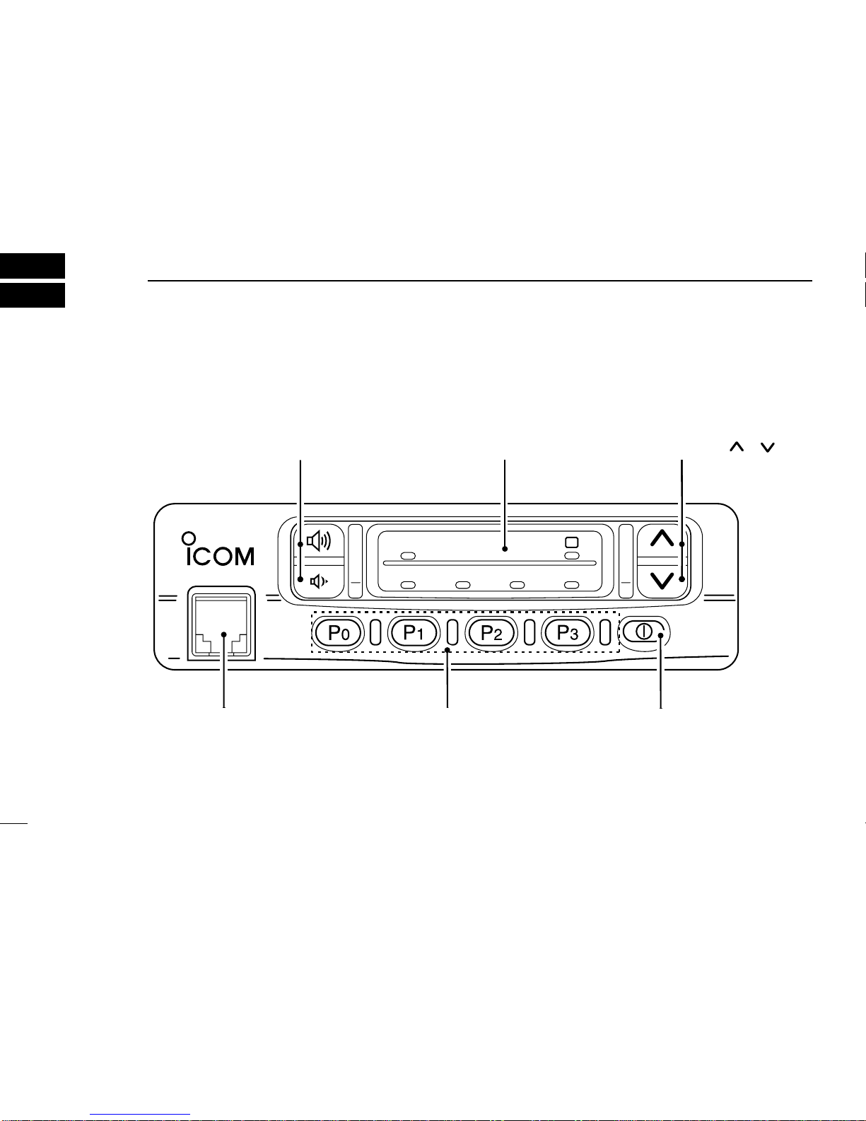
1 PANEL DESCRIPTION ............................................. 1–5
■Front panel ............................................................................ 1
■Function LED ........................................................................ 2
■Programmable function keys ................................................ 3
2 OPERATION ............................................................. 6–8
■Turning power ON ................................................................ 6
■Channel selection ................................................................. 6
■Receiving and transmitting ................................................... 7
DTransmitting notes .......................................................... 7
DDTMF transmission ........................................................ 8
DScrambler function ......................................................... 8
■User set mode ...................................................................... 8
DEntering user set mode .................................................. 8
3 CONNECTION AND MAINTENANCE .................... 9–12
■Rear panel and connection ................................................... 9
■Supplied accessories .......................................................... 10
■Mounting the transceiver...................................................... 11
■Optional UT-96/UT-105/UT-109/UT110 installation ............. 11
■Optional OPC-617 installation ............................................. 12
■Antenna ............................................................................... 12
■Fuse replacement ............................................................... 12
■Cleaning ............................................................................. 12
4 OPTIONAL SmarTrunk II™ OPERATION ........... 13–15
■SmarTrunk II™ and conventional modes ........................... 13
■SmarTrunk II™ operation ................................................... 13
5 OPTIONS .................................................................... 16
DO NOT use or place the transceiver in areas with tem-
peratures below –30°C or above +60°C or, in areas subject
to direct sunlight, such as the dashboard.
AVOID operating the transceiver without running the vehi-
cle’s engine. The vehicle’s battery will quickly run out if the
transceiver is in transmission while the vehicle’s engine is
OFF.
AVOID placing the transceiver in excessively dusty envi-
ronments.
AVOID placing the transceiver against walls. This will ob-
struct heat dissipation.
AVOID the use of chemical agents such as benzine or al-
cohol when cleaning, as they damage the transceiver sur-
faces.
BE CAREFUL! The transceiver will become hot when
operating continuously for long periods.
For U.S.A. only
CAUTION: Changes or modifications to this transceiver, not ex-
pressly approved by Icom Inc., could void your authority to operate
this transceiver under FCC regulations.

1
1
PANEL DESCRIPTION
■Front panel
TX / RX
4321
S
rMICROPHONE
CONNECTOR (p. 2) PROGRAMMABLE
FUNCTION KEYS [P0],[P1],[P2],[P3] (p. 3)
ePOWER SWITCH (p. 2)
FUNCTION LED (p. 2) wCH UP/DOWN KEYS []/[](p. 3)
qVOLUME UP/DOWN KEYS (p. 2)

1
PANEL DESCRIPTION
2
qVOLUME UP/ DOWN KEYS
Push to adjust the audio output level.
• Minimum audio level is pre-programmed.
wCH UP/DOWN [ ]/[ ] KEYS
•Push to select the operating channel.
•Can be programmed for one of several functions by your-
dealer. (See p. 3)
ePOWER SWITCH
Turns the power ON and OFF.
• The following functions are available at power ON as options:
• Automatic scan start
• Password prompt
rMICROPHONE CONNECTOR
Connect the supplied microphone or optional DTMF mi-
crophone for SmarTrunk II™ operation here.
NEVER connect other microphones. The pin assignments
may be different and the transceiver may be damaged.
MICROPHONE
The supplied microphone has a PTT switch and a hanger
hook.
• The following functions are available when the microphone is on
or off hook:
• Automatic scan start when hung up.
• Automatic priority channel selection when off.
• Sets to ‘Inaudible’ condition (mute condition) when hung up.
• Sets to ‘Audible’ condition (unmute condition) when off.
■Function LED
qTRANSMIT/RECEIVE INDICATOR
•Turns red: when transmitting.
•Turns green: when channel is busy.
•Green and red blink simultneously: when the specified 5-
tone call is received.
•Green and red blink alternately: cloning err.
wSELECT INDICATOR
•Lights while bank 2 or CH5 to CH8 is selected. (PMR
model)
•Blinks slowly: talk around. (See p. 4)
•Blinks quickly: enter password.
eCHANNEL INDICATORS
•Indicate the operating channel.
•Blink when receiving a signal during scanning operation.
•All LEDs blink while entering the power ON password.
NOTE:
When all function LED’s blink, check that the DC battery volt-
age is not too high.
S
TX/RX
1234
e
w
q

1
3
PANEL DESCRIPTION
CALL KEYS
Transmit a 5-tone call.
• Call transmission is necessary before you call another sta-
tion depending on your signaling system.
• The [CAL A] and/or [CAL B] keys may be available when
your system employs selective ‘Individual/Group’ calls.
Ask your system operator which call is assigned to each
key.
CH UP AND DOWN KEYS
• Select an operating channel.
DTMF KEY
Push and hold this key to transmit a specified DTMF
code.
EMERGENCY KEY
Push and hold the key to transmit an emergency call.
• If you want to cancel the emergency call, push (or push
and hold) the key again before transmitting the call.
• The emergency call is transmitted one time only or re-
peatedly until receiving a control code depending on the
pre-setting.
LIGHT
Push to select the keybacklight and LED condition.
ON :Turns ON the LEDlight continuously.
OFF :Turns OFF* the LEDlight.
CALL
CAL B
CAL A
BANK
■Programmable function keys
The following functions can be assigned to the programmable
function keys [P0], [P1], [P2], [P3], [ ] and [].
Consult your Icom dealer or system operator for details con-
cerning your transceivers programming.
In the following explanations, programmable function names
are bracketed, the specifc switch used to activate the func-
tion depends on programming.
CH UP
CH DN
BEEP
ATTENUATOR
Push and hold to turn the attenuator function ON.
Push to turn the attenuator function OFF.
NOTE: The attenuator function protects desired
signals from distorting when excessively strong
signals, such as broadcast, pager signals, etc.
are nearby.
BANK KEY (PMR only)
Selects a bank (a group of 4 channels).
• When selecting 4CH×2Bank type, push one or
more times to select a channel bank for conven-
tional channels or SmarTrunk II™ channels.
BEEP
Push to turn the beep tones ON/OFF.
ATT
EMER
DTMF
LITE ON
AUTO
OFF

1
AUTO :Turns ON/OFF depending on the ACC
socket pin 1 voltage.
ON: Low (0 V) OFF: High (12 V)
*Evenwhen turned OFF, the LEDlightsslightly.
OPERATING CHANNEL KEYS
Select an operating channel directly.
OUTPUT POWER SELECTION KEYS
Select the transmit output power temporarily or per-
manently depending on the pre-setting.
• Push and hold to select low power.
• Push to cancel low power.
• Ask your Dealer or System Operator for the output power
level for each selection.
SCAN START/STOP KEY (default [P0])
Push this key to start scanning; and push again to
stop.
NOTE: Place the microphone on hook to start
scanning.
Take the microphone off hook to stop scanning.
4
PANEL DESCRIPTION
PRIORITY CHANNEL KEYS (default [P1])
Select priority A or priority B channel with each push.
TALK AROUND KEY (default [P2])
Push and hold to turn the talk around function ON.
Push to turn the talk around function OFF.
• The talk around function equalizes the transmit frequency
to the receive frequency for mobile-to-mobile communica-
tion.
MONITOR KEY (default [P3])
Activates one of (or two of) the following functions on
each channel independently:
• Push and hold the key to unmute the channel (audio is
emitted; ‘Audible’ condition).
• Push to mute the channel.
• Push the key to toggle the mute and unmute conditions
(toggles ‘Audible’ and ‘Inaudible’).
• Push the key to mute the channel (sets to ‘Inaudible’
only).
• Push the key to unmute the channel (sets to ‘Audible’
only).
• Push the key after the communication is finished to send a
‘reset code’.
NOTE: The unmute condition (‘Audible’ condition)
may automatically return to the mute condition
(‘Inaudible’ condition) after a specified period.
MONI
HIGH
LOW2
LOW1
TA
CH 3
CH 4
CH 1
CH 2
PRI A
PRI B
SCAN

1PANEL DESCRIPTION
5
TRUNKING GROUP SWITCH
Push to select the trunking group.
VOICE SCRAMBLER SWITCH
• Push and hold to turn the voice scrambler function ON.
• Push to turn the voice scrambler function OFF.
NOTE:
•Optional UT-109 (#02) or UT-110 (#02) VOICE
SCRAMBLER UNIT is required.
•IC-F320(420)S’s with serial numbers above
50000 are compatible with voice scrambler
units.
•Contact your dealer for details.
PRODUCT INFORMATION
■This IC-F310/320(F410/420)S’s with se-
rial numbers above 50000 are compati-
ble with the optional UT-109/ UT-110
voice scrambler units.
UT-109: Non-rolling type. 32 code num-
bers are available.
UT-110: Rolling type. Provides higher
communication security. 1020 (4
groups ×255) code numbers are
available.
■This transceiver requires version #02
scrambler units, do not install version
#01, as they are not compatible.
■UT-109 and UT-110 require some PC
board modifications. Please refer to the
additional installation manual.
Please contact your dealer for details.
(See pgs. 5, 8, 11, 18)
GRP
SCRM

■Channel selection
Several types are available, and the channel selection
method may differ according to your system set up.
NON-BANK TYPE:
Push the []/[]keys to select the desired operating
channel, in sequence; or,
push one of the [CH 1] to [CH 4] keys to select these channels
directly.
Select indicator LED lights when CH5 to CH8 is selected.
(PMR 8CH model)
BANK-TYPE: (PMR)
Push [BANK] to select the desired bank number.
Select indicator LED lights when bank 2 is selected.
AUTOMATIC SCAN TYPE:
Channel setting is not necessary for this type. When turning
the power ON, the transceiver automatically starts scanning.
Scanning stops when receiving a call or when taking the mi-
crophone off hook.
S
S
■Turning power ON
qPush [K
I] to turn the power ON.
wIf the transceiver is programmed for a start up passcode,
input digit codes as directed by your System operator.
• The keys in the diagram below can be used for password input:
•The transceiver detects numbers in the same block as identical.
Therefore “1234” and “6789” are the same.
eWhen all channel indicator LEDs still blink after inputting 4
digits, the input code number may be incorrect. Turn
power off and start over in this case.
OPERATION 2
6
KEY
NUMBER
P0P1P2P3
0
51
62
73
84
9

■Receiving and transmitting
RECEIVING:
qPush [K
I] to turn the power ON.
wPush []/[]to select a channel.
eWhen receiving a call, adjust the volume [UP] or [DOWN]
to a comfortable listening level.
TRANSMITTING:
rTake the microphone off hook.
•5-tone mute may be released.
•A priority channel may be selected automatically.
tWait for the channel to become clear.
•The channel is busy when TX/RX LED turns green.
yPush the [CALL] key when initiating a call from your side.
•Coded audio may be heard from the transceiver.
•This operation may not be necessary depending on your signal-
ing system. Ask your system operator or dealer.
uWhile pushing and holding [PTT], speak into the micro-
phone at your normal voice level.
iRelease [PTT] to receive.
IMPORTANT: To maximize the readability of your signal:
(1) pause briefly after pushing [PTT], (2) hold the trans-
ceiver 15 to 20 cm from your mouth, then speak into the
microphone at a normal voice level.
2OPERATION
7
DTransmitting notes
•Transmit inhibit function
The transceiver has several lockout/inhibit functions which re-
strict transmission under the following conditions:
•The channel is in mute condition.
•Channel is busy.
•No matched (or matched) CTCSS is received.
•The selected channel is a ‘receive only’channel.
•Time-out timer
After continuous transmission for a pre-programmed period,
the time-out timer is activated causing the transceiver to stop
transmitting and automatically select receive.
•Penalty timer
Once the time-out timer is activated, transmission is further
inhibited for a period determined by the penalty timer.

2
OPERATION
8
DDTMF transmission
If the transceiver has a [
DTMF
] key, the automatic DTMF
transmission function is available.
DScrambler function
A UT-109 (#02) or UT-110 (#02) optional voice scrambler unit
provides hight performance private communication between
stations with the same scrambler codes.
qPush and hold [
SCRM
] to scrambler function ON.
wPush [SCRM] to turn the function OFF.
NOTE:
•UT-109 (#02) non-rolling type scrambler unit has 32 code
numbers. UT-110 (#02) rolling type scrambler unit has
1020 (4 groups ×255) code numbers
•IC-F320(420)S’s with serial numbers above 50000 are
compatible with voice scrambler units.
Contact your dealer for details.
■User set mode
User set mode is accessed at power ON and allows you to set
seldom-changed settings. in this case you can “customize”
transceiver operation to suit your preferences and operating
style.
DEntering the user set mode
qWhile pushing and holding []and [ ], push [K
I] to
turn the user set mode ON, allowing you to set seldom-
changed settings.
wLED blinks quickly.
Available set mode functions
•Push [P 0] to set AF minimum level
•Push [P 1] to set beep ON or OFF
•Push [P 2] to set LED brightness
•Push [P 3] to set squelch level
ePush [K
I] again to exit set mode.
S

CONNECTION AND MAINTENANCE
3
9
■Rear panel and connection Antenna
red: +
black: _
Supplied DC
power cable
Optional speaker
(SP-10, SP-22)
Optional cable
(OPC-617)
t
q
w
e
r

3
CONNECTION AND MAINTENANCE
10
⁄ANTENNA CONNECTOR
Connects to an antenna. Ask your dealer about antenna
selection and placement. (See p. 12)
¤MICROPHONE HANGER
Connect the supplied microphone hanger to the vehicle’s
ground for on/off hook microphone functions. (See p. 2)
‹DC POWER RECEPTACLE
Connects to a 12 V DC battery. Pay attention to polarities.
NEVER connect to a 24 V battery. This could damage the
transceiver.
›EXTERNAL SPEAKER JACK
Connect a 4–8 Ωexternal speaker, if desired.
fiOPTIONAL CABLE (OPC-617)
Connect an external modem unit, LCD backlight control,
etc.
■Supplied Accessories
qMicrophone ...................... 1
(Some versions may not be sup-
plied with a microphone)
wMicrophone hanger and
screw set ..................... 1 set
eMicrophone hanger cable . 1
rDC power cable .................1
IC-F310S/F410S: OPC-345
IC-F320S/F420S: OPC-346
tMounting bracket .............. 1
yBracket bolts ..................... 4
uMounting screws (M5×12) . 4
iSelf-tapping screws
(M5×20) ............................. 4
oFlat washers ...................... 4
!0 Spring washers ................. 4
!1 Nuts ................................... 4
!2 Fuses ............................... 2
IC-F310S/F410S: 15 A
IC-F320S/F420S: 20 A
!3 Function name stickers*
1705 LCD SEAL(A) ..........1
D*Function name stickers
There are no names on the programmable function keys since the
needed functions can be assigned to these keys.
Attach the supplied function name stickers above the appropriate
keys.
12
3
4
56
7
8
90 A B C
LCD-STICKER

■Mounting the transceiver
The universal mounting bracket supplied with your transceiver
allows overhead mounting. Please read the following instruc-
tions carefully.
•Mount the transceiver securely with the 4 supplied screws
to a sturdy surface which can support more then 1.5 kg.
3CONNECTION AND MAINTENANCE
11
■Optional UT-96/UT-105/UT-109
and UT-110 installation
The optional UT-96/UT-105/UT-109 and UT-110 units install
as follows:
qTurn power OFF, then disconnect the DC power cable.
wUnscrew the 4 screws, then remove the bottom cover.
eInstall the unit as shown in the diagram below.
rReplace the bottom cover and screws, then the DC power
cable.
NOTE:
•UT-109 and UT-110 require some PC board modifica-
tions. Please refer to the additional installation manual.
•This transceiver requires #02 type scrambler units, do not
install #01 types, as they are not compatible.
•The sponge supplied with the UT-105 is for the IC-F30/ F40 series
transceivers only.
Flat washer
Spring washer
When using
self-tapping screws

3
CONNECTION AND MAINTENANCE
12
■Antenna
A key element in the performance of any communication sys-
tem is an antenna. Ask your dealer about antennas and the
best places to mount them.
■Fuse replacement
Two fuses are installed in the supplied DC power cable. If a
fuse blows or the transceiver stops functioning, track down
the source of the problem, if possible, and replace the dam-
aged fuse with a new, rated one.
❑Fuse rating IC-F310S/F410S: 15 A, IC-F320S/F420S: 20 A
■Cleaning
If the transceiver becomes dusty or dirty, wipe it clean with a
dry, soft cloth.
AVOID the use of solvents such as benzene or al-
cohol, as they may damage transceiver surfaces.
q
LED light cont. IN
wAF OUT
eDet. AF OUT
rMod. IN
tPTT control IN
yHorn drive cont. OUT
uAF GND
iDet. AF GND
oMod. GND
OPTIONAL CABLE PIN ASSIGNMENT
trewq
oiuy
■Optional OPC-617 installation
Install the OPC-617 as shown below.

OPTIONAL SmarTrunk II™OPERATION
4
13
■SmarTrunk II™and
conventional modes
This transceiver is capable of SmarTrunk II™functions.
The optional UT-105 allows communication in conventional
channels or SmarTrunk II™channels.
NOTE: Connect an optional HM-100T DTMF MICRO-
PHONE. Contact your dealer for details.
■SmarTrunk II™operation
These features are enabled by a dealer or system operator
and may not be available in your system. Contact your dealer
for details.
DPlacing a telephone call
Enter the phone number followed by [1], [M].
•A high-pitched beep indicates that the number is accepted.
•When the called party answers, push the [PTT] switch to talk, and
release it to listen.
DCalling another local system subscriber
Enter the subscriber number followed by [3], [M].
•A high-pitched beep indicates that the number is accepted.
•You hear ringing, then two short beeps when the subscriber an-
swers.
•If the other subscriber is on another call or out of range, you hear a
fast busy signal and the call terminates automatically.
DReceiving a call
When you hear ringing, push [M] to answer.
•For a group call, you hear a short ring followed by two short beeps.
You do not have to answer a group call to hear it over the air.

4
OPTIONAL SmarTrunk II™OPERATION
14
DTerminating a call
After completing a call, push [#] to disconnect (hang up).
IMPORTANT: If one person in the conversation terminates
a call, all participants will be cut off.
DLast number redial
Push [M], [M] to automatically redial the last number called.
•A high-pitched beep indicates that the number is accepted.
DMemory speed-dialing
To automatically dial a commonly used number from memory:
•Push [M] followed by the memory location (0–9).
DTurbo SpeeDial
To automatically dial a commonly used number with one
push:
•Push one of the turbo SpeeDials ([A], [B], [C] or [D]).
DProgramming memory speed dial
qPush and hold [M] until you hear a high-pitched beep.
wEnter the memory location (0–9, A, B, C, D), the telephone
or subscriber number, then [1], [M] (or [3], [M] if for another
system subscriber).
•A high-pitched beep indicates successful programming.
•Memories [A]–[D] are used for the Turbo SpeeDial.
DSystem busy indication
If all channels are busy, three low beeps sound after you initi-
ate a call. Try the call again later.
DPTT dispatch operation
qPush [PTT] once (without dialing) to initiate a dispatch call.
wBegin talking after you hear three beeps (one short, high-
pitched, two very-short, low-pitched).
eReceiving a dispatch call is indicated by the same three-
beep sequence.
•It is not necessary to push [M] to answer a dispatch call.
DEmergency call
Push [0], [M] to initiate an emergency call.
•Contact your dealer for details.

4OPTIONAL SmarTrunk II™OPERATION
15
DClear channel alerting
If all channels are busy, the transceiver automatically begins
searching for an open channel and beeps every ten seconds.
When two short beeps (low-pitched, then high-pitched) are
heard, a channel is available. Push [M], [M] immediately to re-
dial the last number.
NOTE: For additional operating instructions, contact your
dealer or system operator.

5
EXTERNAL SPEAKERS
SP-5
Large speaker for good audio
quality.
Input impedance: 4 Ω
Max. input power: 5 W
SP-10
Compact and easy-to-install.
Input impedance: 4 Ω
Max. input power: 5 W
SP-22
Compact and easy-to-install
Input impedance: 4 Ω
Max. input power: 5 W
MICROPHONES
HM-100T
DTMF microphone.
HM-100
Normal microphone.
16
OPTIONS
OTHER UNITS
UT-96 5-TONE UNIT
Provides 2-tone/5-tone signaling.
UT-105 SmarTrunk II™Logic
Board
Provides SmarTrunk II™capabili-
ties.
UT-109/UT-110 VOICE SCRAM-
BLER UNIT
•UT-109: Non-rolling type (max. 32
codes)
•UT-110: Rolling type (max. 1020
codes)
OPC-617 ACC CABLE
Allows you to connect to an exter-
nal terminal.
UT-109
UT-110

6-9-16 Kamihigashi, Hirano-ku, Osaka 547-0002 Japan
A-5560D-1EX
Printed in Japan
©1998 by Icom Inc.
This manual suits for next models
3
Table of contents
Other Icom Transceiver manuals