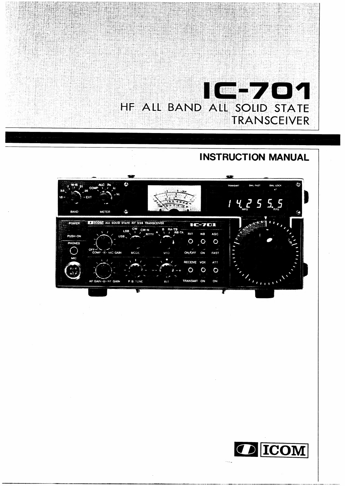
Icom IC-701 User manual

\LL
SOLID
STATE
__
TRANSCEIVER
METER
WRICOM
Ait
sous
state
ON/OFF
ON
RECEIVE
VOX
a-+
O
1°)
o
AF
GAIN~-®>
AF
GAIN
P.B.TUNE
TRANSMIT
ON ON

SECTION
SECTION
SECTION
SECTION
4-1
4-2
4-3
SECTION
5-1
5-2
5-3
5-4
5-5
SECTION
6-1
6-2
6-3
6-4
6-5
6-6
SECTION
pe
Fe2
7-3
ie
SECTION
SECTION
SECTION
SECTION
il;
(SRECIRICGATIONS
+2225
Grete
ecg
taadeeep
colds
eu
aen
ae
eet
autos
seat
1
im
a
OOS
lc
ee
eee
eee
Lee
en
Oe
ee
ee
ETS
OM
See
eee
eee
Mee
ere
ee
2
So:
INSTALLATION
4
ccs
ties
ors
oles
Ma
See
oe
ae
UES
oa
oe
ae
tote
ua
aaa
e
3
4
“OPE
RAIING
CONTROLS:
220305
co
eeh
eaten
d
Sheu
heap
ake
ened
ce
6
POINT
AINE
Eos
ce
sree
treats
tivo
a
anatase,
ned
eal
dr
act
hd
aieew
Heaton
ga
Soe
daa
Re
6
CONTROLS
“UNDER
ACCESS
COVER.
<s4.ncerx
tov
ee
tee
iees
dee
twee
Sed
ea
9
REAL:
FANEL
CONNECTIONS
2c
224i
eee
atta
toud
beeeteu
ate
agote
ww
Dome
Se
10
BD
-OPERATING:
INSTRUCTIONS.
of2
Qos
econ
aus
wlacs
1043543
tounge
cede
11
PLOW
Oe
TUNE
acco
un
Mie,
ah
ik
decade
cares
ain aon
te
athe
Strate
bkitiniies
Sige
Ses
OSB
orate
aed
11
SoS
OPERATION
Ac
feces
Joe
ccate
Pensls
PA
SARS
a
Sib
eee
eee
ee
ee
Oana
woe
Basan
13
CW
OPER
AT
ON!
shit
ee
dee
te
ee
tee
Makee
wen
earwemuee
we
ehe
beeen
ee
eae
15
Be
ee
DOIN
2
ccs
th
Get
ene
Poe
gh
ie
ee
ee
eit
teens,
wee
eae
ae
Gleretaouene
ee
ae
15
OLAER
“OPERATIONS
-4
ox
ieee
aoe
Sete
Gat
nee
os
eam
aera
eed
oe
oes
4
i
CO
THEOR
tsi
uc
os
teeters
aU
Rees
ae
sao
aes
20
ER
Ee
crits
Se
Sea
gh
hed
ae
tats
tty
heats
Shee
ope
Spree
cee
Siete
ea,
it
ci
Rt
es
Rien
ate
20
PAINS
ME
cctsinchics
te
Rat
ita
eats,
So
crite
em
gules
Aa
tcl
Wed
ieee
Sie
dare
Se le
ite
aie
ba
we
i
23
PEL“
(Pitase
bocked
‘oop
UNI
Wc.
«os.
s
bocr
sith
ise
w
alspoisk
se
Aunt
Bunton
ed
eee
26
PVE
INT
oot
i
tcp
te
es
eat
ey
Ses
See
ei
woe
Ss er
he
pare
erate
at
am
cane
Ste
ehehah
aha
28
PWV
Eh
IN
se
ote
st
apa
oterrenh
oh
2
kes
ta
eases
ty
wee
edo
oranda
aoe
eee
gh
ene
ea
ouins
32
OTLAER
CRG
GIW
ALY
sini
dv
eon
ate
a
gn
eee
8
oto
es
Sceuie
Satan
ee
eit
a
ened
BG
Bd
32
7
MAINFENANCE-AND
ADJUSTMENT
0
vc4
ces
oa
ele
ees
tee
oe
fee
OX
at
eo
ies
34
MEASURING
INSTRUMENTS
REQUIRED
FOR
ADJUSTMENT.............----
34
RECEIVER
ADJUSTMENT).
2)
scaamgciot
eae.
ieay
Se
ieah
sea
ee
te
teat
as
PAs
34
ERANS
MARV
FER:
ADIUSTMEN
To.
emiea
gave
Obata
tema
als
ein
we
Seine
oe
¢
36
Piss
GIN
(ADDU
SMEG
2
3-i,
og
ote
oh
ace
o
tase
cheat
ile
Medien
ts
Ariat
ated
Rade
Rr
ee
Y
38
S
TROUBEE
SHOOTING)
2
230
ccaneuac-ct
ns
ome
ene
oan
a
lee
aihiy
ae
40
Os:
TINS
TD
WE
<8
9
ere
ne
ooo
Be
ce
Deeb
eee
cae
a
wth
bo
le
a
ere
ind
arene
Wane
ec
tiol
42
1O>
-WORTAGE“CHARWS
ices
isdn
tte
lt
Bien
ceeded
eS
oe
Sone
ee
aunatneh
S
BaE
at;
44
TT
VBROCK
DIAGRAM
wx
oo
atoued
Ga
ten
he
bi
eee
eae
ke
see
eae
Sane
ae
48
eta
ton
seine
Rann
SSA
AAs
nine
ik
acini
mst
NA
RRR
bORintt
it
ARNIS
aL
ap
witecntesneenannetc
RRNA
cn
deme
mh
tn

SECTION
|
SPECIFICATIONS
GENERAL
Number
of
Semi-Conductors:
Transistors
128
FET
23
IC
(Includes
LS!1)
56
Diodes
265
Frequency
Coverage:
1.8MHz
~
2.0MHz
3.5MHz
~
4.0MHz
7.0MHz
~
7.5MHz
(7.3MHz~7.5MHz
Receive
Only)
14.0MHz~15.2MHz
(14.35MHz~15.2MHz
Receive
Only)
21.0MHz~21.5MHz
28.0MHz~30.0MHz
(28.0MHz~29.7MHz
Transmit
Range)
Frequency
Control:
LSI
based
100Hz
step
Digital
PLL
synthesizer.
Independent
Transmit-Receive
Frequency
Available
on
same
band.
TRANSMITTER
DC
Input
Power:
SSB
(A3J)
200
Watts
CW
(Ai),
RTTY
(Fi)
200
Watts
Continuously
Adjustable
Output
power
0~Max.
Emission
Mode:
A3J
SSB
(Upper
sideband
and
Lower
sideband)
Al
CW
Fi
RTTY
(Frequency
Shift
Keying)
Harmonic
Output:
More
than
40dB
below
peak
power
output
Spurious
Output:
More
than
60dB
below
peak
power
output
Carrier
Suppression:
More
than
40dB
below
peak
power
output
Unwanted
Sideband:
More
than
40dB
down
at
1000Hz
AF
input
Microphone:
Impedance
600
ohms
Input
Level
10
millivolts
typical
Dynamic
or
Electret
Condenser
Microphone
Frequency
Readout:
6
digit
LED
100Hz
readout.
Frequency
Stability:
Less
than
500Hz
after
switch
on
1
min
to
60
mins,
and
less
than
100Hz
after
1
hour.
Less
than
1KHz
in
the
range
of—10°C
to
+60
°C.
Power
Supply
Requirements:
DC
13.6V
+15%
Negative
ground
Current
drain
18
A
max.
(at
200W
input)
AC
power
supply
speaker
console
is
available
for
AC
operation.
Antenna
!mpedance:
50
ohms
Unbalanced
Weight:
7.3Kg
Dimensions:
111mm
x
241mm
x
311mm
(H
x
W
x
L)
RECEIVER
Receiving
System:
Triple
Conversion
Superheterodyne
with
continuous
Bandwidth
Control
Receiving
Mode:
Ai,
A3J
(USB,
LSB)
Fi
(Output
FSK
audio
signal)
IF
Frequencies:
Ist
9.0115MHz
2nd
10.75MHz
3rd
9.0115MHz
with
continuous
Bandwidth
Control
Sensitivity:
Less
than
0.25
microvolts
for
10dB
S+N/N
Selectivity:
SSB.
RTTY
+1.2KHz
at
—6dB
(Adjustable
to
+0.5KHz
Min)
+2.0KHz
at
—60dB
CW
+250Hz
at
—6dB
+700Hz
at
—60dB
CW-N
+100Hz
at
—6dB
+500Hz
at
—60dB
(with
Audio
Filter)
Spurious
Response
Rejection
Ratio:
More
than
60dB
Audio
Output:
More
than
1.5
Watts
Audio
Output
Impedance:
8
ohms
oe
ann
en
MR
er
niente
mae
eeshdeetnpedtnnnanie
ote
tennant

SECTION
2
FEATURES
ALL.
BAND,
ALL
MODE,
ALL
SOLID
STATE
The
IC-701
covers
all
the
Amateur
HF
frequencies
from
1.8MHz
to
29.999.9MHz
plus
15MHz
WWV.
It
offers
not
only
SSB,
but
also
CW
and
RTTY.
All
of
the
circuits
in
the
IC-701,
including
the
driver
and
final
power
stages
are
completely
solid
state,
and
provide
about
100
Watts
output.
COMPUTER
COMPATIBLE
TUNING
SYSTEM
The
local
oscillator
circuit
(VFO)
employs
a
C-MOS
LSI!
for
the
PLL
that
has
been
custom-made
on
the
basis
of
ICOM’s
advanced
digital
technology.
The
VFO
circuit
is
a
digital
PLL
circuit
that
controls
frequency
determination
by
pulses
produced
by
the
tuning
control.
Unlike
conventional
PLLs,
it
controls
the
VCO
by
combining
and
dividing
crystal
oscillator
frequencies.
Therefore,
its
stability
is
much
higher
than
conventional
VFOs.
In
addition,
the
pulse
control
system
makes
it
possible
to
set
and
change
frequencies
with
external
digital
signals.
With
a
computer
programmed
and
connected
to
the
rear
accessory
socket,
you
can
easily
control
frequencies,
change
bands,
scan,
on
the
IC-701.
This
system
will
give
you
the
maximum
of
performance
and
versatility.
DUAL
DIGITAL
VFO’S
The
IC-701
contains
two
built-in
digital
VFO’s
located
in
ICOM’s
custom
LSI,
providing
the
ultimate
in
versitility.
DIGITAL
READOUT
AND
FULL
METERING
The
frequency
is
presented
in
bright
easy
to
read
LEDs,
with
no
backlash
or
waiting
time.
The
mulit-function
meter
shows
you
relative
signal
strength
in
receive,
power
output,
ALC,
SWR,
compression
level,
final
transistor
voltage
and
current.
All
the
important
information
you
need
to
know.
PASS
BAND
TUNING AND
SPEECH
PROCESSOR
The
IC-701
has
a
built-in
Pass
Band
Tuning
system
developed
by
ICOM
that
allows
you
to
continuously
adjust
the
pass
band
of
the
IF.
By
turning
the
control,
you
can
eliminate
interference
from
a
nearby
signal,
thus
providing
clear
reception.
It
can
also
be
used
as
a
tone
control.
During
transmit,
the
Pass
Band
Tuning
circuit
can
be
used
as
a
Speech
Processor
providing
increased
“talk
power”
for
outstanding
D
Xing.
OUTSTANDING
PERFORMANCE
The
RF
amplifier
circuit
using
MOS
FETs,
the
Schottky
barrier
diode
balanced
mixer
and
other
circuits
provide
excellent
Cross
Modulation
and
Two-Signal
Selectivity
characteristics.
The
IC-701
has
excellent
sensitivity
demanded
especially
for
mobile
operation,
high
stability,
and
with
two
Crystal
Filters
having
high
shape
factors,
exceptional
selectivity.
The
Same
Schottky
diode
mixer
is
used
in
the
transmitter,
and,
with
the
band
pass
filter
and
high
performance
K-Constant
two
stage
low-pass
filter,
ensures
transmission
of
pure
signals
with
very
low
spurious
emission.
ADDITIONAL
CIRCUITS
The
IC-701
has
a
built-in
Noise
Blanker,
VOX,
an
Auto
Dimmer
for
control
of
the
readout
and
meter
illumination,
CW
Monitor,
APC,
SWR
detector,
and
many
other
circuits
for
your
convenience.
The
IC-701
has
everything
you
need
to
really
enjoy
HF
operation,
in
an
extremely
compact,
rugged
transceiver.
enim
ase
aetna
thecbaet
ts
talc
etna
easement
einen
es
mate
we
sonnet,

SECTION
3
INSTALLATION
BE
SURE
TO
READ
THE
FOLLOWING
INSTRUCTIONS
BEFORE
USE.
3-1
UNPACKING
Carefully
remove
your
transceiver
from
the
packing
carton
and
examine
it
for
signs
of
shipping
damage.
Should
any
be
apparent,
notify
the
delivering
carrier
or
dealer
im-
mediately,
stating
the
full
extent
of
the
damage.
It
is
recommended
you
keep
the
shipping
cartons.
In
the
event
storage,
moving,
or
reshipment
becomes
necessary
they
will
be
handy.
Accessory
cables,
plugs,
etc.,
are
packed
with
the
transceiver.
Make
sure
you
have
not
overlooked
anything.
1.
Microphone
(1C-SM2)
..........
0.0.
e
eee eee eee
1
2.
External
Speaker
Plug...
..
2.0.0...
cc
ee
eee
wees
1
Oe
SCV
FIUG*
oo
tack
ne
ieee
an
tee
seek
e
te
ee
oe
tee
1
4.
Scope
Terminal
Plug...........
0.0.02
eee
eens
1
5.
Transverter
terminal
Plug
.............005
0
eee
1
6.
Spare
Fuse
(20
Amp)
...........
000
ee
eee
eeee
2
7;
DG,
Power
Cord’.
oe
adie
Set
ied
yee
ee
es
1
8.
Accessory
Plug
(24
Pin)
............02
0c
eee
1
GO:
Accessory
Plug
PINs
-
3-4
ewiiwat-
ie
oa
ek
Sat
es
24
10.
Accessory
Plug
Boot
............
0c
cece
eee
eens
1
3-2
RECOMMENDATIONS
FOR
INSTALLATION
1.
Avoid
placing
the
IC-701
in
direct
sunlight,
high
temperature,
dusty
or
humid
places.
2.
The
left
side
of
the
unit,
when
facing
it,
functions
also
as
a
heatsink.
The
temperature
there
will
usually
become
relatively
warm
during
transmission.
Any
equipment
should
be
at
least
1
inch
(83cm)
away
from
the
unit
so
as
to
provide
good
ventilation.
Be
sure
that
nothing
is
on
and
just
behind
the
rear
PA
heatsink
to
ensure
good
ventilation.
Also
avoid
places
near
outlets
of
heaters,
air
conditioners
etc.
3.
Place
the
unit
so
that
the
controls
and
switches
can
easily
be
handled
and
the
frequency
indication
and
meter
can
easily
be
read.
4.
For
mobile
installation,
an
optional
mounting
bracket
is
available.
Select
the
best
location
that
can
stand
the
weight
of
the
unit
and
that
does
not
interfere
with
your
driving
in
any
way.
5.
Use
the
Ground
Lug!
3-3
POWER
SUPPLY
For
AC
operation,
use
the
special
power
supply
!C-701PS.
If
you
would
like
to
use
your
car
battery
or
any
other
DC
power
supply,
be
sure
that
its
output
voltage
is
12-15
Volts
and
the
current
capacity
is
at
least
20
Amps.
The
maximum
power
consumption
of
the
set
during
transmission
runs
from
16-20
Amps,
so
keep
that
in
mind
if
the
unit
is
installed
in
your
automobile,
and
turn
it
on
after
you
have
started
the
engine.
Attention
should
also
be
paid
to
the
condition
of
the
battery
and
electrical
system.
The
connection
of
the
DC
power
cord
supplied
with
the
1C-701
is
done
in
the
following
way:
First
make
sure
that
the
power
switch
of
the
unit
is
in
the
OFF
position
and
the
T/R
switch
is
in
the
receive
position.
Connect
the
cord
to
the
DC
power
supply
with
the
RED
lead
to
the
positive
terminal
and
the
BLACK
lead
to
the
negative
terminal.
(Reverse
connection
will
cause
the
protection
circuit
to
operate
and
blow
the
fuse.)
Connect
the
DC
plug
to
the
socket
on
the
rear
panel
of
the
!C-701.
Refer
to
the
drawing
below.
a
seas
O
A
|
1C-701PS
:
pSeRR
ER
RESEREREESES
AC
POWER
OUTLET
For
AC
operation
BATTERY
or
De
POWER
SOURCE
DC
POWER
CORD
For
DC
operation
3-4
ANTENNA
Antennas
play
a
very
important
role
in
radio
communi-
cation.
If
the
antenna
is
inferior,
your
transceiver
cannot
give
you
the
best
performance.
With
a
good
antenna
and
feeder
cable
having
50
ohm
impedance,
you
should
easily
get
the
desired
matching
and
performance.
Carefully
install
a
high
performance
antenna
that
suits
the
frequency
band(s)
you
wish
to
operate
on
and
place
it
as
high
as
possible.
Be
especially
careful
of
the
condition
of
the
connectors
as
loose
connections
will
deteriorate
the
per-
formance.
Be
sure
to
connect
the
ground
terminal
of
a
whip
antenna,
if
used,
to
the
body
of
your
car.
As
the
output
is
quite
high,
avoid
connecting
the
antenna
connector
to
open
lines
and
do
not
transmit
under
mismatched
conditions.
Otherwise
the
final
stage
could
be
overloaded
and
cause
a
malfunction
of
the
unit.
—-3-
eset
peas
soccer
nce
at
mene
it
rE
EN
tn
metic
pasciciien
neil
OMe
Ne
tele
ten
in
inet
te
eA
Bm
Mr
a
et

3-5
GROUND
In
order
to
prevent
electrical
shocks,
TVI,
BC!
and
other
problems,
be
sure
to
connect
a
heavy
wire
ground,
as
short
as
possible,
from
a
good
earth
point
to
the
ground
terminal
on
the
rear
panel.
3-6
MICROPHONE
The
microphone
supplied
with
the
IC-701
is
the
IC-SM2
which
contains
a
pre-amplifier.
It’s
circuit
diagram
is
shown
below.
The
IC-SM2
is
an
Electret
Condenser
type
microphone.
Schematic
diagram
of
IC-SM2
R7
200M
(2)
°
3
3
7]
°
o
°
TR1,
TR2:
2SC536
or
equivalent
A
sensitivity
contro!
is
installed
on
the
bottom
side
of
the
mic
stand.
By
turning
it
in
the
“’H”
or
“L”
direction,
the
sensitivity
will
increase
or
decrease
respectively.
Adjust
the
control
so
as
to
get
the
proper
sensitivity
considering
the
distance
to
the
mic,
the
loudness
of
your
voice
and
the
environmental
conditions.
The
wind
screen
not
only
prevents
background
noise
due
to
wind,
but
also
protects
the
mic.
Unless
required,
do
not
remove
the
screen
from
the
mic.
In
order
to
operate
the
microphone,
connect
its
plug
to
the
mic
socket
on
the
IC-701.
To
transmit,
press
the
PTT
switch
downward.
When
it
is
released,
the
IC-701
will
return
to
the
receive
condition.
For
a
long
transmis-
sion,
pull
the
PTT
switch
back
while
pressing
it
down
until
the
switch
is
locked
and
it
will
remain
in
that
position
until
it is
pushed
forward
and
released.
LOCK
RELEASE
Key
Wiring
Diagram
If
you
would
like
to
use
a
different
microphone
in
your
car,
an
optional
hand
held
dynamic
microphone
is
available.
If
other
types
of
microphones
are
used,
be
sure
their
impedance
is
between
500-600
ohms,
and
connect
a
4
pin
plug
in
the
manner
shown.
Microphone
plug
exploded
view
Microphone
connection
Microphone
(cord
side
view)
3-7
CW
KEY
When
operating
CW,
connect
the
Key
to
the
Key
Jack
with
the
plug
supplied.
The
connection
of
the
plug
is
shown
below.
If
the
terminals
have
polarity,
be
sure
to
make
the
correct
connection.
Note
that
the
keyed
voltage
when
switching
with
semiconductors
or
relays
with
resistors
in
the
circuit,
should
be
adjusted
to
be
below
0.4
Volts!
3-8
RTTY
When
operating
RTTY,
connect
the
ACC
socket
pins
8
(ground)
and
9
to
your
tele-typewriter
through
a
high
speed
relay
or
a
level
converter
to
TTL
level,
and
the
tones
for
your
terminal
unit
will
be
available
from
pin
4.
For
details,
refer
to
“How
to
use
RTTY”,
and
“Transmit
and
Receive”’
sections
in
this
manual.

3-9
EXTERNAL
SPEAKER
The
IC-701
contains
an
internal
speaker,
and
is
also
designed
so
that
it
can
drive
an
external
speaker
from
the
external
(EXT)
speaker
jack
on
the
rear
panel.
Be
sure
the
impedance
of
the
external
speaker
is
8
ohms,
and
remember
that
with
the
external
speaker
connected,
the
internal
speaker
is
disabled.
3-10
HEADPHONES
Any
good
headphone
set,
including
stereo
type,
that
have
4-16
ohms
impedance
can
be
used.
With
the
plug
inserted
halfway
into
the
PHONES
jack,
both
the
headphone
and
speaker
will
operate. This
is
convenient
when
others
wish
to
listen
in
on
the
station,
or
you
wish
to
record
contacts
using
a
tape
recorder
connected
to
the
headphone
jack.
With
a
stereo
headphone
set
inserted
this
way,
however,
the
headphone
will
lose
the
sound
on
one
side.
With
the
plug
inserted
completely,
only
the
headphone
works.
3-11
POWER
SUPPLY
It is
highly
recommended
that
you
use
the
[C-701PS
power
supply
for
base
operation.
If
you
wish
to
use
another
power
source,
make
sure
that
it
meets
the
voltage,
current,
and
regulation
requirements.
Pay
particular
attention
to
the
overvoltage
protection
as
a
runaway
regulator
can
destroy
the
IC-701.
Make
certain
that
more
than
18
Volts
does
not
get
applied
to
the
unit.
When
the
power
switch
is
in
the
ON
position,
do
not
connect
the
power
cord,
antenna,
external
speaker,
Accessory
plug,
or
the
mi-
crophone
to
avoid
possible
trouble.
Be
sure
not
to
transmit
with
the
antenna
disconnected.
If
the
fuse
blows,
replace
it
with
a
new
20
Amp
fuse
after
fixing
the
cause.
Avoid
turning
the
power
switch
ON
and
OFF
repeatedly
over
a
short time.
Frequent
repetitions
may
cause
the
frequency
indicator
to
display
the
wrong
frequencies.
If
such
a
malfunction
should
occur,
turn
OFF
the
switch
and
a
few
seconds
later
turn
it
ON
again.
3-12
CAUTIONS
As
the
unit
has
already
been
closely
adjusted
with
highly
sophisticated
measuring
instruments,
never
tamper
with
the
turnable
resistors,
coils,
trimmers,
etc.
IN
THE
PLL
UNIT,
THE
HEART
OF
THE
TRAN-
SCEIVER,
A
C-MOS
LSI
IS
INCORPORATED.
IF
THE
SEAL
IS
BROKEN
WHEN
A
FAILURE
OCCURS
WITHIN
THE
TERMS
OF
THE
GUARANTEE,
THE
REPAIR
MAY
BE
AT
THE
USERS
EXPENSE,
SO
DO
NOT
ATTEMPT
TO
OPEN
THE
PLL
CASE!
C-MOS
is
also
used
in
the
digital
driver
unit
as
well
as
the
PLL.
C-MOS
ICs
are
very
susceptible
to
excessive
static
charges
and
over
current
and
care
must
be
used
when
handling
them.
Therefore,
avoid
touching
the
driver
unit
and
the
nearby
circuitry
unless
absolutely
necessary.
When
it
is
necessary
to
check
the
circuitry,
observe
the
following
points.
Ground
all
measuring
instruments,
the
soldering
iron,
and
other
tools.
Do
not
connect
or
disconnect
the
C-MOS
IC
from
its
socket,
or
solder
it
when
the
power
is
ON.
Do
not
apply
voltage
of
less
than
—0.5
or
more
than
+5
Volts
to
the
input
terminals
of
the
IC.
DO
NOT
MEASURE
WITH
AN
OHMMETER.
3-13
COOLING
FAN
The
rear
of
the
PA
unit
is
designed
to
achieve
effective
natural
cooling.
But
with
200
Watts
input,
the
final
stage
circuit
produces
quite
a
bit
of
heat
and
its
temperature
may
rise
during
a
very
long,
continuous
transmission.
If
the
temperature
becomes
high
enough,
the
built-in
cooling
fan
will
start
to
spin.
The
fan
is
connected
to
the
temperature
monitoring
circuit
which
detects
the
temperature
of
the
final
stage
transistors.
The
operation
of
this
fan
is
as
follows:
1.
The
fan
does
not
work
during
all
reception.
2.
During
transmission,
it
does
not
work
if
the
detected
temperature
is
below
a
certain
level.
3.
When
the
temperature
exceeds
that
level
during
a
transmission,
the
fan
will
start
to
move
air
across
the
heatsink
to
cool
it.
4.
If
the
temperature
of
the
final
stage
transistors
rises
to
the
danger
point,
the
fan
will
turn
at
a
much
higher
speed
and
frequency
display
will
start
to
flash.
THIS
MEANS
STOP
TRANSMITTING!
1,
2
and
3
are
normal
conditions.
4
is
abnormal.
If
the
meter
and
display
start
to
flash,
stop
transmitting
and
check
for
the
cause
of
the
excess
heat.
This
could
be
antenna
mismatch,
environmental
problems,
etc.,
but
be
sure
to
rectify
the
problem
before
beginning
to
operate
again.
—5—
i
er
A
ae
waa
tnt
So
eS
aR
OR
lm
Li
tS
AORN
eR
ON
the
ene
en
BAM
enh
Rr

SECTION
4
OPERATING
CONTROLS
4-1
FRONT
PANEL
@
DIAL
LOCK
INDICATOR
LED
@
FREQUENCY
DISPLAY
@
DIAL
TS
INDICATOR
LED
@
TRANSMIT
INDICATOR
LED
@
MULTI-FUNCTION
METER
78
5
ALC
Po
ef
ee
COMP
4.4
“io
35
Sm!
>
aT
@
BAND
SWITCH
en
mr
(.
@®
METER
SELECT
whe
SWITCH
rd
@
POWER
SWITCH
®
PHONES
JACK—33
®
MIC
CONNECTORS
/
4
WB.
TINE
/’
fj
i
@
COMP
(SPEECH
PROCESSOR)
CONTROL
@®
MIC
GAIN
CONTROL
@
AF
GAIN
CONTROL
@
RF
GAIN
CONTROL
@
MODE
SELECT
SWITCH
(PASS
BAND
TUNING
(
VFO
SWITCH
@
RIT
CONTROL
1.
BAND
SWITCH
The
BAND
SELECT
SWITCH
is
a
7
position
rotary
switch
used
for
selecting
one
of
the
6
Amateur
bands
covered
by
the
IC-701
with
a
7th
position
for
external
control.
The
selectable
bands
are
1.8MHz,
3.5MHz,
7MHz,
14MHz,
21MHz
and
28MHz.
In
the
EXT
position,
the
band
can
be
selected
remotely.
However,
the
switch
should
not
be
put
in
the
EXT
position
without
having
the
remote
control
connected.
This
will
cause
the
rotary
switch
to
rotate
continuously
and
may
cause
excessive
wear
or
damage.
2.
MULTI-FUNCTION
METER
With
the
{C-701
in
the
receive
mode,
this
meter
acts
as
an
S
meter
regardless
of
the
position
of
the
meter
select
—-6-—-
11c-70O8
8
RATB
-
.
Lo
SBR
pit
NB
oRaC
ee,
@
DIAL
LOCK
BUTTON
@
TUNING
CONTROL
KNOB
@
TUNING
SPEED
BUTTON
12
AGC
SWITCH
@
ATTENUATOR
SWITCH
(®
NOISE
BLANKER
SWITCH
(9
VOX
SWITCH
1)
RIT
SWITCH
@
TRANSMIT/RECEIVE
SWITCH
switch.
Signal
strength
is
indicated
on
a
scale
of
$1-S9
and
$9+20dB
to
S9+60dB.
In
the
transmit
mode,
the
meter
has
5
functions
as
outlined
below
which
are
selected
by
the
meter
select
switch.
3.
METER
SELECT
SWITCH
In
the
transmit
mode
the
meter
has
5
functions.
1.
Ve
Indicates
the
collector
voltage
of
the
final
transistors.
2.
Ic
Indicates
the
collector
current
of
the
final
transistors.
3.
Po
Indicates
the
relative
output
power.
SWR
can
eenicnenne
eines
te
cca
area
ah
ete
ast
at
ea
ORthtee
am
iat
ne
nlite
nee
EEE
Ane
aoe
emabaeSiNeS
|

be
measured
by
placing
the
SWR/SWR
SET
switch
in
the
SWR
position.
(This
switch
is
located
under
the
access
cover
on
the
top
of
the
IC-701.
4.
ALC
In
this
position,
the
meter
begins
to
function
when
the
RF
output
power
reaches
a
certain
level.
5.
COMP
Indicates
the
compression
level
when
the
speech
processor
is
in
use.
4.
POWER
SWITCH
The
POWER
SWITCH
is
a
push-lock
type
switch
which
controls
the
input
DC
power
to
the
IC-701.
When
the
external
AC
power
supply
(IC-701PS)
is
used,
the
switch
also
acts
as
the
AC
power
supply
switch.
When
the
switch
is
pushed
in
and
locked,
power
is
supplied
to
the
set.
When
the
switch
is
pushed
again
and
released,
power
is
cut
to
all
circuits
except
the
PA
unit.
5,
PHONE
JACK
This
jack
accepts
a
standard
1/4
inch
headphone
plug
for
a
4-16
ohm
headphone
set.
Stereo
headphones
can
be
used
without
modification.
6.
MIC
CONNECTOR
Connect
the
supplied
microphone
or
optional
microphone
to
this
jack.
If
you
wish
to
use
a
different
microphone
than
the
IC-SM2,
refer
to
the
drawing
on
page
4.
Mic-
rophone
impedance
should
be
500-600
ohms.
7.
COMP
(SPEECH
PROCESSOR)
CONTROL
The
IC-701
contains
a
built-in
RF
speech
processor
which
is
turned
ON
by
turning
the
center
knob
clockwise
from
the
OFF
position
(a
click
will
be
heard).
In
the
ON
position
it
works
as
the
RF
drive
control
as
explained
below.
In
the
CW
and
RTTY
modes,
it
works
as
the
output
level
control
of
the
IC-701.
When
RF
speech
processor
operation
is
not
desired,
the
COMP
control
should
be
turned
completely
counter-clockwise
and
clicked
OFF.
8.
MIC
GAIN
CONTROL
Adjusts
the
level
of
modulation
according
to
the
input
of
the
microphone.
Clockwise
rotation
increases
microphone
gain.
As
the
input
will
vary
with
different
microphones
and
different
voices,
the
knob
should
be
turned
until
the
MULTI-FUNCTION
METER
needle,
in
the
ALC
mode,
starts
to
move
slightly
within
the
ALC
zone.
In
the
SSB
mode,
with
the
RF
speech
processor
in
use,
the
MIC
GAIN
CONTROL
sets
the
clipping
limits,
while
the
COMP
control
sets
the
RF
drive
level
up
to
the
maximum
power
level
where
ALC
begins
at
the
saturation
point
of
the
amplifiers.
9.
AF
GAIN
CONTROL
Controls
the
audio
output
level
in
the
receive
mode.
Clockwise
rotation
increases
audio
output.
10.
RF
GAIN
CONTROL
Controls
the
gain
of
the
RF
section
in
the
receive
mode.
Clockwise
rotation
gives
the
maximum
gain.
As
the
control
is
rotated
counter-clockwise,
the
needle
of
the
MULTI-FUNCTION
METER
rises,
and
only
signals
stronger
than
the
level
indicated
by
the
needle
will
be
heard.
11.
MODE
SELECT
SWITCH
This
switch
selects
the
mode
of
operation
for
both
transmit
and
receive.
USB
Upper
Sideband,
mainly
for
14,
21
and
28MHz
bands.
LSB
Lower
Sideband,
mainly
for
1.8,
3.5
and
7MHz
bands.
CW
Continuous
Wave,
for
CW
operation
on
all
bands.
~CW-N
Narrow
CW.
The
audio
band-pass
filter
is
auto-
matically
turned
ON
in
this
position
to
improve
selectivity
when
receiving.
RTTY
Radio
Teletype.
For
use
on
all
available
bands.
12.
P.
B.
TUNE
(PASS
BAND
TUNING)
CONTROL
This
control
allows
continuous
tuning
of
the
pass
band
selectivity
moving
the
edge
of
the
filter
up
to
1.5KHz
from
either
the
upper
or
lower
side
in
SSB
and
RTTY.
This
not
only
improves
selectivity,
but
also
can
improve
the
audio
quality.
The
normal
position
is
in
the
center
(12:00
o'clock) position
and
is
2.4KHz
wide
in
SSB.
13.
VFO
SWITCH
With
this
switch
you
can
select
the
VFO
you
want
to
operate
from
two
separate
VFO’s
that
are
built-in
to
the
IC-701.
It
also
selects
the
relationship
of
the
two
VFO’s.
The
switch
performs
the
following
operations
according
to
its
position.
*
A:
Selects
““A’’
VFO
for
both
transmit
and
receive.
*
B:
Selects
‘“B’’
VFO
for
both
transmit
and
receive.
*
RA-TB
:
Selects
‘““A’’
VFO
for
receive
and
‘B’’
VFO
for
transmit.
*
RB-TA:
Selects
‘‘B’’
VFO
for
receive
and
“A’’
VFO
for
transmit.
In
addition,
when
the
VFO
is
switched
from
“‘A’’
VFO
to
“B’
VEO,
the
frequency
indicated
on
the
frequency
display
just
prior
to
switching
goes
into
a
memory
inside
the
LSI.
Thus
even
if
‘“B’’
VFO
is
being
used,
switching
to
“A”
again
will
enable
you
to
operate
at
the
initial
frequency.
Switching
from
“‘B”
to
“A”
results
in
the
same
operation.
However,
if
switching
is
done
with
the
BAND
SWITCH
(or
external
control),
the
VFO
frequency
displayed
will
disappear
and
the
lower
end
frequency
of
the
band
selected
will
be
displayed.
If
you
wish
to
operate
on
the
frequency
that
was
memorized
in
the
VFO
that
was
not
used
when
switching
bands,
simply
return
to
the
original
band
and
then
to
the
other
VFO
and
the
initiall
memorized
frequency
will
appear.
more
detail
later
in
this
manual.
This
is
explained
in
14.
RIT
CONTROL
Shifts
the
receiver
frequency
+800Hz
either
side
of
the
transmit
frequency.
When
the
RIT
is
ON,
the
RIT
LED
is
illuminated.
The
LED
also
represents
the
‘‘0’’
position.
Rotating
the
control
to
the
(+)
side
raises
the
receiver
frequency,
and
rotating
to
the
(—)
side
lowers
the
receiver
frequency.
With
the
RIT
ON,
if
the
tuning
knob
@j)
is
moved
one
increment,
the
RIT
circuit
is
automatically
pulsed
OFF.
Therefore
it
is
not
necessary
to
manually
turn
—TJT-—-
net
eee
Mea
attra
ear
petri
seememagmicatsrimrtn
jm
wneraeecevainnth
tenses
pote
sateen
AR
eR
an
AR
nk
NS
bint
atin
ae
BER
see

OFF
the
RIT
when
changing
operating
frequency.
The
frequency
shift
by
tuning
the
RIT
Control
is
not
indicated
on
the
frequency
display.
15.
RIT
SWITCH
This
is
a
spring-loaded
switch
for
the
RIT
control.
To
turn
ON
the
RIT,
push
down
once.
If
OFF
is
desired,
push
down
again.
When
the
RIT
is
ON
the
LED
above
the
RIT
control
knob
is
lit.
This
also
indicates
the
center
position
of
the
RIT
control.
With
the
RIT
circuit
OFF
the
LED
is
also
OFF.
Also
if
the
RIT
is
ON
and
the
Tuning
Knob
is
rotated
one
increment
it
will
pulse
the
RIT
OFF
unless
the
internal
jumper
has
been
changed.
16.
NB
(NOISE
BLANKER)
SWITCH
When
pulse
type
noise
such
as
automobile
ignition
noise
is
present,
set
this
switch
to
the
ON
(down)
position.
The
noise
will
be
reduced
to
provide
comfortable
reception.
17.
AGC
(AUTOMATIC
GAIN
CONTROL)
SWITCH
With
this
switch
you
can
change
the
time
constant
on
the
AGC
circuit.
With
the
switch
in
the
AGC
(up)
position,
the
circuit
operates
as
a
‘“hang’’
AGC
and
maintains
the
AGC
voltage
for
a
specific
time,
thus
it is
suitable
for
SSB
reception.
With
the
switch
in
the
FAST
(down)
position,
the
circuit
is
OFF,
and
AGC
is
suitable
for
stations
suffering
from
fast
fading
or
operating
in
the
CW
mode.
18.
TRANSMIT/RECEIVE
(T/R)
SWITCH
This
switch
is
for
manually
switching
from
transmit
to
receive
and
vice
versa.
Set
the
switch
to
RECEIVE
(up)
and
the
!C-701
is
in
the
receive
mode.
Set
the
switch
to
TRANSMIT
(down)
and
it
switches
to
transmit.
When
switching
with
the
PTT
switch
on
the
microphone
or
with
the
VOX
switch
set
to
ON
the
T/R
switch
must
be
in
the
RECEIVE
position.
19.
VOX
SWITCH
This
switches
the
VOX
circuit
ON
and
OFF.
When
it
is
in
the
ON
(down)
position,
in
SSB,
T/R
switching
is
accomplished
by
means
of
a
voice
signal.
!n
CW
operation,
semi-break-in
switching
by
means
of
keying
is
possible.
20.
ATT
(ATTENUATOR)
SWITCH
Turn
the
ATT
switch
ON
(down)
when
strong
nearby
signals
disturb
signal
reception
or
make
“’S”
readings
difficult.
in
the
ON
position,
a
10dB
attenuator
is
inserted
into
the
receiving
antenna
circuit,
reducing
interfering
signals
and
giving
more
stable
reception.
In
normal
operation
the
ATT
switch
is
left
in
the
OFF
(up)
position.
21.
TUNING
CONTROL
KNOB
Rotating
the
TUNING
CONTROL
KNOB
clockwise
in-
creases
the
frequency,
while
rotating
it
counter-clockwise
decreases
the
frequency.
The
frequency
is
changed
in
100Hz
steps
which
correspond
to
the
smaller
vernier
marks
on
the
knob.
The
larger
marks
represent
1KHz
steps.
One
complete
rotation
of
the
tuning
knob
results
in
a
5KHz
frequency
increase
or
decrease
in
100Hz
steps
exactly
as
shown
by
the
small
vernier
marks.
22.
TUNING
SPEED
BUTTON
Pushing
the
TUNING
SPEED
BUTTON
will
illuminate
the
DIAL
FAST
display
LED,
and
the
small
vernier
marks
on
the
tuning
knob
are
changed
to
correspond
to
10KHz
steps.
At
the
same
time,
the
1KHz
and
100Hz
digits
are
cleared
on
the
display
to
show
‘0.0’...
When
the
Tuning
Speed
Button
is
depressed
again,
the
dial
fast
display
LED
goes
OFF
and
the
small
vernier
marks
will
again
correspond
to
100Hz
steps.
This
button
will
allow
you
to
quickly
QSY
over
a
great
frequency
range.
23.
DIAL
LOCK
BUTTON
After
the
IC-701
is
set
to
a
certain
frequency
for
rag
chewing,
mobile
operation,
etc.,
pushing
the
DIAL
LOCK
BUTTON
will
illuminate
the
DIAL
LOCK
display
LED
and
the
VFO
is
electronically
locked
at
the
displayed
frequency,
thus
inactivating
the
operation
of
the
tuning
knob.
To
change
frequency,
the
dial
lock
must
first
be
disengaged
by
pushing
the
dial
lock
button
again.
The
dial
lock
display
LED
will
go
OFF
and
the
frequency
will
change
with
the
direction
of
the
tuning
knob
rotation.
Turning
the
power
OFF
will
release
the
dial
lock
and
clear
the
displayed
frequency.
24.
FREQUENCY
DISPLAY
The
frequency
of
the
IC-701
is
displayed
on
7
segment
LEDs.
Since
the
1MHz
and
1KHz
decimal
points
are
displayed,
the
frequency
can
easily
be
read.
The
fre-
quencies
indicated
are
the
carrier
frequencies
of
each
mode
in
USB,
LSB
and
CW.
In
the
RTTY
mode,
the
space
frequency
is
displayed.
Since
the
local
oscillation
frequency
is
shifted
in
accordance
with
modes,
no
tuning
will
be
required
if
you
change
modes.
Remember,
if
you
turn
the
RIT
control
ON
to
change
the
receive
frequency
and
rotate
the
RIT
control
knob,
the
frequency
displayed
will
not
change.
25.
TRANSMIT
INDICATOR
LED
When
your
set
is
in
the
transmit
mode,
this
LED
is
lit.
26.
DIAL
TUNING
SPEED
INDICATOR
LED
illuminates
when
the
TUNING
SPEED
BUTTON
is
pressed
to
set
the
dial
to
fast
tuning.
27.
DIAL
LOCK
INDICATOR
LED
illuminates
when
the
DIAL
LOCK
BUTTON
is
pressed
to
lock
the
dial.
ntineinn
se
tonal
sine
is
ANN
denna
neh
sense
min
ml

4-2
CONTROLS
UNDER
ACCESS
COVER
@
DIM
SWITCH
@RTTY
SHIFT
SWITCH
@
SWR
SWITCH
6)
CW
MONITOR
CONTROL
2
SWR
SET
CONTROL
@
FREQUENCY
SET
CONTROL
DIM
GAIN
CONTROL
28.
DIM
SWITCH
When
this
switch
is
set
to
DIM,
the
luminosity
of
the
frequency
display
and
the
meter
automatically
decreases
when
the
ambient
level
is
reduced
below
a
set
level.
Therefore,
under
dim
lighting
such
as
at
night,
it
decreases
the
luminosity
to
a
lower
level
for
easy
indicator
reading.
When
the
switch
is
at
the
OFF
position,
the
dimmer
function
is
disabled.
29.
RTTY
SHIFT
SWITCH
This
switch
shifts
transmit
frequency
and
shift
spacing.
Normally
the
shift
is
170Hz,
but
in
some
cases
850Hz
is
still
used.
Set
the
switch
for
the
desired
shift.
30.
SWR
SWITCH
When
measuring
SWR,
calibration
SET
and
SWR
reading
functions
are
selected
with
this
switch.
Remember,
at
the
factory,
the
switch
is
in
the
SET
position
and
fixed
in
place
with
a
plastic
screw
to
prevent
it
from
switching
to
SWR.
Remove
the
screw
before
attempting
to
read
SWR!
SWR
must
be
read
only
in
the
Po
meter
position.
31.
CW
MONITOR
(MONI)
CONTROL
This
control
adjusts
the
audio
volume
of
the
side
tone
(monitor)
audio
during
CW
transmit
operation.
Adjust
it
to
your
desired
level
for
easy
listening.
32.
SWR
SET
CONTROL
This
control
calibrates
the
meter
needle
to
the
Po
SET
position
when
you
want
to
determine
the
value
of
SWR.
The
meter
must
be
in
the
Po
position
and
the
set
must
be
transmitting
a
carrier.
ete
er
7
ee
2
6)
VOX
DELAY
CONTROL
8
ANTI
VOX
CONTROL
6)
CW
DELAY
CONTROL
6)
VOX
GAIN
CONTROL
33.
FREQUENCY
SET
CONTROL
This
control
is
for
fine
adjustment
of
the
VXO
section
frequency
of
the
PLL
unit,
which
is
the
local
oscillator
frequency.
Do
not
turn
it
unless
you
want
to
change
the
frequency.
34.
VOX
GAIN
CONTROL
This
control
adjusts
input
signal
level
via
the
microphone
to
the
VOX
circuit.
For
VOX
operation
in
SSB,
adjust
the
control
so
that
the
VOX
circuit
will
operate
with
normal
speech.
35.
CW
DELAY
(CW
time
delay
constant)
CONTROL
In
Semi-break-in
CW
operation,
this
controls
the
TX/RX
switchover
time
delay.
Adjust
it
to
suit
your
keying
speed.
36.
ANTI
VOX
CONTROL
In
VOX
(SSB)
operation,
the
VOX
circuit
may
be
operated
by
sound
from
the
speaker
causing
a
switch
to
transmit.
This
trouble
can
be
prevented
by
adjusting
the
input
level
of
the
ANTI
VOX
circuit
with
this
contro!
along
with
the
VOX
gain
control
so
that
the
VOX
circuit
only
operates
from
the
operator’s
voice,
not
by
sound
from
the
speaker.
37.
VOX
DELAY
(VOX
time
constant)
CONTROL
This
controls
the
TX
to
RX
switching
time.
Adjust
it
so
TX
to
RX
switching
will
not
occur
during
short
pauses
in
normal
speech.
38.
DIM
GAIN
(dimmer
circuit)
CONTROL
The
threshold
for
the
functioning
of
the
dimmer
circuit
can
be
adjusted
by
turning
the
DIM
GAIN
CONTROL.
Turning
the
control
counter-clockwise
will
lower
the
operation
threshold
of
the
circuit.
—-9Q—
estate
ca
ce
ops
A
AER
nna
A
ec
anhee
tanecmnnt
bee

4-3
REAR
PANEL
CONNECTIONS
6)
RECEIVER
INPUT
TERMINAL
@
RECEIVER
ANTENNA
OUTPUT
TERMINAL
@ANTTENA
CONNECTOR
@EXTERNAL
SPEAKER
JACK
@KEY
JACK
@FUSE
HOLDER
@
GROUND
TERMINAL
39.
RECEIVER
INPUT
TERMINAL
This
is
an
input
terminal
which
is
connected
directly
to
the
receiver.
40.
RECEIVER
ANTENNA
OUTPUT
TERMINAL
This
is
a
terminal
to
which
received
signals
from
the
~
antenna
connector
are
conducted
after
the
signal
passes
through
the
transmit/receive
antenna
switching
circuit.
Usually
the
receiver
IN
and
OUT
terminals
are
jumpered.
The
receiver
antenna
output
terminal
is
usually
used
when
another
receiver
is
used
or
a
pre-amplifier
is
connected
to
the
IC-701.
41.
ANTENNA
(ANT)
CONNECTOR
This
is
used
to
connect
the
antenna
to
the
set.
Its
impedance
is
50
ohms
and
connects
with
a
PL
259
connector.
42.
EXTERNAL
SPEAKER
JACK
When
an
external
speaker
is
used,
connect
it
to
this
jack.
Use
a
speaker
with
an
impedance
of
8
ohms.
When
the
external
speaker
is
connected,
the
built-in
speaker
does
not
function.
43.
KEY
JACK
For
CW
operation,
connect
the
key
here.
For
electronic
keying
the
terminal
voltage
must
be
less
than
0.4V
DC.
44.
FUSE
HOLDER
This
holds
the
fuse
for
the
DC
power
circuit.
If
the
fuse
is
blown,
replace
it
with.a
new
20
Amp
fuse
after
checking
the
cause.
Open
the
fuse
holder
with
a
Phillips
head
driver.
4)SCOPE
TERMINAL
@TRANSVERTER
TERMINAL
@
ACCESSORY
SOCKET
POWER
SOCKET
45.
GROUND
TERMINAL
To
prevent
electrical
shock,
TVI,
BCI
and
other
problems,
be
sure
to
ground
the
equipment
through
the
GROUND
TERMINAL.
For
best
results
use
as
heavy
a
gauge
wire
or
strap
as
possible
and
make
the
connection
as
short
as
possible,
even
in
mobile
installations.
46.
POWER
SOCKET
Connect
the
DC
power
cord
or
cable
from
the
!C-701PS
or
suitable
DC
source
to
this
connector.
47.
ACC
(ACCESSORY)
SOCKET
Accessories
and
controls
can
be
used
with
the
IC-701
and
connected
to
the
ACC
socket
on
the
rear
panel.
NOTE:
Pins
14-24
are
terminals
for
digital
control
and
are
con-
nected
to
the
input
terminal
of
the
C-MOS
IC.
By
no
means
apply
any
voltage
not
within
the
range
of
—0.5
to
+5
Volts.
For
details,
refer
to
page
20.
48.
X-VERTER
(TRANSVERTER)
TERMINAL
VHF
and
UHF
operation
using
a
suitable
transverter
with
the
IC-701
is
possible.
This
terminal
is
for
Transverter
connection.
The
output
is
a
few
milliwatts.
Refer
to
the
tranverters
instruction
for
recommended
hookup.
49.
SCOPE
TERMINAL
This
terminal
brings
out
the
9.011MHz
IF
signal
from
the
mixer
in
the
receiver.
Not
only
observation
of
the
received
signal,
but
also
of
signals
of
a
the
selected
band
width
are
possible
by
using
a
panadaptor
or
panascope.
rican
nian
nce
ican
re
ORE
setennnkttnenncniahe
ned
ath
ela
Deceit
MM
A
ANN
Renn
nN
EAA
BONE:
A

SECTION
5
OPERATING
INSTRUCTIONS
5-1
HOW
TO
TUNE
The
following
instructions
are
for
tuning
in
any
mode.
Please
read
carefully
and
understand
fully
before
turning
on
your
unit.
Proper
tuning
is
necessary
for
optimum
operation.
5-1-1
TUNING
KNOB
The
transmit
or
receive
frequency
is
displayed
on
7
segment
LEDs
down
to
100Hz
digits.
Rotating
the
tuning
knob
clockwise
increases
the
frequency,
while
turning
counter-
clockwise
decreases
the
frequency
in
100Hz
steps.
The
smaller
vernier
marks
on
the
knob
represent
100Hz
and
the
larger
marks
represent
1KHz.
One
complete
rotation
of
the
tuning
knob
results
in
a
5KHz
frequency
increase
or
decrease.
When
you
receive
your
set,
calibration
of
the
tuning
knob
may
be
desirable,
as
the
large
increments
may
not
correspond
exactly
to
a
change
of
1KHz
displayed
on
the
LEDs.
Exact
calibration
is
not
necessary
as
the
displayed
LED
frequency
will
always
be
correct,
but
you
may
calibrate
the
scale
on
the
tuning
knob
for
use
as
an
analog
type
frequency
display.
To
calibrate,
set
a
large
increment
on
the
tuning
scale
to
line
up
with
the
indicator
arrow
directly
above
the
scale
and
then
turn
ON
the
power.
To
calibrate
the
scale
during
operation,
if
desired,
set
a
large
increment
on
the
tuning
scale
to
line
up
with
the
indicator
arrow
and
then
push
the
tuning
speed
button
TWICE.
By
doing
so,
the
1KHz
and
100Hz
digits
are
cleared
on
the
display
to
show
“0.0”.
The
tuning
knob
scale
may
require
recalibration
if
you:
1.
Turn
the
knob
while
the
frequency
is
locked
by
use
of
the
Dial
Lock
Button.
2.
Use
the
tuning
speed
button
when
a
large
increment
is
not
lined
up
with
the
indicator.
3.
Turn
the
knob
beyond
the
band
edge.
If
the
knob
is
too
loose
or
too
stiff
for
comforatble
use,
you
can
adjust
the
torque
by
tightening
or
loosening
the
brake
adjustment
screw
accessable
from
underneath
the
set.
Brake
adjustment
screw
Brake
Adjustment
The
following
instructions
should
be
used
to
adjust
the
tension
of
the
Tuning
Knob.
1.
Remove
the
bottom
cover
of
the
IC-701.
2.
The
Tuning
knob
tension
will
become
tighter
by
turning
the
brake
adjustment
screw
clockwise,
and
will
become
looser
by
turning
the
screw
counterclockwise.
3.
While
performing
this
adjustment,
the
Tuning
knob
must
be
turned
continuously
as
the
screw
is
adjusted
in
order
to
set
the
tension
for
a
comfortable
touch.
4.
After
the
adjustment
has
been
made,
replace
the
bottom
cover.
On
all
but
the
28MHz
band,
the
displayed
frequency
will
not
go
beyond
the
highest
band
edge
even
by
turning
the
tuning
knob
clockwise,
or
beyond
the
lowest
band
edge
by
turning
the
knob
counter-clockwise.
On
the
28MHz
band,
since
this
band
width
is
much
wider
than
the
others,
the
IC-701
provides
“‘automatic
revert’’
for
operating
con-
venience.
When
the
frequency
display
shows
29.999.9MHz
and
the
tuning
knob
is
turned
clockwise,
the
displayed
frequency
jumps
down
to
28.000.0MHz
and
continues
up
from
there.
Likewise,
by
continuing
to
turn
counter-clock-
wise
beyond
the
bottom
edge
of
the
band,
the
frequency
jumps
up
from
28.000.0MHz
to
29.999.9MHz
and
goes
down
from
that
point.
The
displayed
frequency
shows
the
carrier
frequency
in
the
USB,
LSB
and
CW
modes,
and
the
SPACE
frequency
in
the
RTTY
mode.
Therefore
recalibration
of
the
frequency
is
unnecessary
when
the
mode
is
changed.
5-1-2
DIAL
LOCK
BUTTON
After
the
IC-701
is
set
at
a
certain
frequency
for
rag
chew-
ing,
mobile
operation,
etc.,
pushing
the
Dial
Lock
button
will
illuminate
the
Dial
Lock
LED
and
the
VFO
is
locked
at
the
displayed
frequency,
thus
inactivating
the
operation
of
the
tuning
knob.
To
change
the
frequency,
the
Dial
Lock
must
first
be
disengaged
by
pushing
the
dial
lock
button
again.
The
Dial
Lock
display
LED
will
go
OFF,
and
the
frequency
will
change
with
the
direction
of
the
tuning
Knob
rotation.
Turning
OFF
the
power
will
release
the
Dial
Lock
and
clear
the
displayed
frequency.
5-1-3
TUNING
SPEED
BUTTON
Pushing
the
Tuning
Speed
Button
will
illuminate
the
dial
fast
LED
and
the
small
vernier
marks
on
the
Tuning
Knob
is
changed
to
correspond
to
10KHz
steps.
At
the
same
time,
the
1KHz
and
100Hz
digits
are
cleared
on
the
display
to
show
‘0.0’...
When
the
Tuning
Speed
Button
is
depressed
again,
the
dial
fast
display
LED
goes
OFF
and
the
small
vernier
marks
will
again
correspond
to
100Hz
steps.
This
button
will
allow
you
to
quickly
OSY
over
a
great
frequency
range.
5-1-4
VFO
SELECT
SWITCH
The
LSI
in
the
IC-701
contains
two
‘‘VFO’s”
for
both
receiving
and
transmitting.
The
VFO’s
are
labeled
“A”.
VFO
and
“‘B”
VFO
and
are
selectable
with
the
VFO
Select
Switch.
This
dual
VFO
system
gives
the
IC-701
many
very
convenient
features.
Please
read
this
section
very
carefully
and
perform
the
operation
several
times
until
you
are
comfortable
with
the
system.
tannin
ania
anteeaieien
cee
AC
IINORN
Ni
anak
eh
EES
EEC
CATON
CLOT
et
A
OT
LOLOL
LEE
AA
A
A
IEE
IIA
A
co
tna
AG
cen
ase
ted
atte
sna
Saeatoeenmacename
ot
mnaeinese
in
nese
nme
te
debe
ct
tila
dS
AN
nea
men

“1.
“A”
VEO
is
for
both
transmitting
and
receiving
and
is
selected
by
placing
the
VFO
Select
switch
in
the
“A”
position.
The
transmit
and
receive
frequency
will
be
controlled
by
“A’’
VFO,
displayed
on
the
LED
fre-
quency
readout,
and
stored
in
“A"
memory.
2.
““B’
VEO
is
for
both
transmitting
and
receiving
and
is
selected
by
placing
the
VFO
Select
switch
in
the
“B”’
position.
The
transmit
and
receive
frequency
will
be
controlled
by
“‘B’’
VFO,
displayed
on
the
LED
fre-
quency
readout,
and
stored
in
‘“B’’
memory.
3.
RA-TB:
The
receive
frequency
is
controlled
by
“A”
VFO
and
the
transmit
frequency
is
controlled
by
“B”’
VFO.
Both
frequencies
are
stored
in
their
respective
memories,
and
displayed
during
their
respective
ope-
ration
times
(““A’”
frequency
during
receive,
and
“B”’
frequency
during
transmit).
4.
RB-TA:
The
receive
frequency
is
controlled
by
“’B”
VFO
and
the
transmit
frequency
is
controlled
by
“A”
VFO,
the
reverse
of
the
above.
Again,
both
frequencies
are
stored
in
their
respective
memories,
and
displayed
during
their
respective
operation
times
(this
time
“B”’
frequency
during
receive
and
‘A’
frequency
during
transmit).
When
the
!IC-701
is
first
turned
ON,
the
frequency
displayed
on
the
LED
readout
is
the
lowest
frequency
limit
of
the
band
selected
by
the
band
switch.
FOR
EXAMPLE:
lf
the
band
switch
is
set
to
the
7MHz
band,
when
the
set
is
turned
ON,
7.000.0
will
be
displayed
on
the
LED
readout.
This
will
occur
whether
the
VFO
switch
is
in
either
the
“A”’
or
“B’
or
combination
VFO
position.
Rotating
the
tuning
knob
clockwise
will
increase
the
frequency
in
100Hz
steps.
Rotating
the
tuning
knob
counter-clockwise
will
decrease
the
frequency
in
100Hz
steps.
Note:
Rotating
the
knob
counter-clockwise
immediately
after
applying
power
will
not
lower
the
frequency
as
it
is
already
at
the
lowest
limit.
Switching
from
one
VEO
to
the
other
VFO
does
not
clear
the
first
VFO.
The
frequency
is
retained
in
the
VFO’s
memory.
EXAMPLE
lf
14.125.0MHz
is
set
with
““A’’
VFO,
and
the
VFO
switch
is
set
to
““B’’
VFO,
the
frequency
LED
readout
will
show
“B’’
VEQO’s
frequency,
but
14.125.0MHz
is
still
stored
in
“A”
VEQ’s
memory.
Returning
the
VFO
switch
to
“A”
VFO
position,
and
14.125.0
will
be
displayed
on
the
readout.
Accordingly,
if
the
switch
is
placed
in
the
“’B”
VFO
position,
the
frequency
that
was
set
with
the
“‘B”’
VFO
will
appear.
This
allows
you
to
set
a
certain
frequency
with
one
VFO,
work
up
and
down
the
band
with
the
other
VFO,
and
periodically
check
the
set
frequency
simply
by
switching
between
“A”
and
“B”
VFO.
It
also
allows
you
to
search
for
aclear
frequency
with
one
VFO,
while
keeping
your
operating
frequency
on
the
other
VFO.
When
you
have
found
a
clear
frequency,
switch
back
to
your
operating
frequency,
inform
the
station
you
are
in
contact
with
of
the
new
frequency,
and
switch
back.
It’s
that
simple!
The
1C-701
will
perform
this
operation
even
on
two
dif-
ferent
bands.
A
frequency
is
set
in
either
“A”
or
“B’’
VFO
on
one
band,
the
VFO
switch
is
set
to
the
other
VFO,
and
the
band
switch
set
to
any
other
band
you
wish
to
work.
When
you
want
to
go
back
to
the
set
frequency,
first
return
to
the
original
band
and
then
to
the
original
VFO
and
you’re
back
on
the
set
frequency.
FOR
EXAMPLE
Set
“A”
VFO
to
14.255.0MHz.
Set
the
VFO
switch
to
“B’’
VFO.
Switch
to
the
21MHz
band.
The
frequency
readout
will
read
21.000.0MHz.
Operate
anywhere
you
wish with
“B’
VFO.
When
you
want
to
return
to
14.255.0MHz,
first
switch
back
to
the
14MHz
band.
Then
switch
to
“‘A’’
VFO
and
the
frequency
readout
wil!
show
14.255.0MHz.
When
recalling
a
memorized
frequency
be
sure
to
turn
OF
F
the
dial
fast
circuit.
If
the
circuit
is
not
turned
OFF,
the
memorized
frequency’s
1KHz
and
100Hz
digits
will
both
revert
to
“0”.
RA-TB/RB-TA
These
positions
will
allow
you
to
operate
split
transmit/
receive
frequencies
on
the
same
band.
EXAMPLE:
Set
“A”
VFO
to
14.350.0MHz
and
“‘B”
VFO
to
14.255.0
MHz.
Then
set
the
VFO
select
switch
to
the
RA-TB
position.
14.350MHz
will
shown
on
the
readout
during
receive
(“A’
VFO)
and
14.255.0MHz
during
transmit
(“B’
VFO).
You
are
now
receiving
on
14.350.0MHz
and
transmitting
on
14.255.0MHz.
Setting
the
VFO
select
switch
to
RB-TA
re
rses
the
above.
Changing
bands
in
these
modes
resets
both
“A”
and
‘‘B”’
VFO
to
the
lowest
band
limit.
5-1-5
RIT
(RECEIVER
INCREMEMTAL
TUNING)
By
using
the
RIT
circuit,
you
can
shift
the
receive
fre-
quency
+800Hz
either
side
of
the
transmit
frequency
without
moving
the
transmit
frequency
itself.
Therefore,
|
when
you
get
a
call
slightly
off
frequency,
or
when
the
other
station’s
frequency
has
shifted,
you
can
tune
in
the
frequency
without
disturbing
the
transmitting
frequency.
By
pushing
the
RIT
switch
down
once
(it’s
a
spring
loaded
switch)
the
RIT
circuit
is
turned
ON
and
the
RIT
LED
is
lit.
The
receive
frequency
is
shifted
with
the
RIT
knob.
When
the
RIT
knob
is
in
the
“0”
position,
the
transmitting
and
receiving
frequencies
are
the
same.
Rotating
the
control
to
the
(+)
side
raises
the
receiving
frequency,
and
rotating
to
the
(—)
side
lowers
the
frequency.
To
turn
OFF
the
RIT
control,
again
push
on
the
RIT
switch
and
the
RIT
LED
will
go
OFF.
When
the
RIT
circuit
is
OFF,
the
transmit
and
receive
frequencies
are
the
same
regardless
of
a
ean
Minna
le
ap
A
me
ote
sates
nen
dnt
sh
nh
chin
hd
i
je
aerate
A

the
setting
of
the
RIT
contro!
knob.
When
the
RIT
circuit
is
ON,
if
the
tuning
knob
is
moved
by
one
increment,
the
RIT
circuit
is
automatically
pulsed
OFF.
However,
this
function
can
be
eliminated
by
changing
the
connecting
pins
in
the
driver
unit
as
shown
below,
in
case
you
would
like
the
RIT
to
remain
operational
when
you
turn
the
tuning
knob.
Or,
by
continuously
depressing
the
RIT
switch
with
your
finger
while
turning
the
tuning
knob,
the
RIT
circuit
will
remain
operational
while
tuning.
Other
things
to
remember
are:
The
RIT
circuit
is
ope-
rational
when
the
frequency
is
locked
with
the
dial
lock
button.
The
frequency
shifted
by
turning
the
RIT
control
is
not
indicated
on
the
frequency
display.
When
the
transmitting
and
receiving
frequencies
differ
by
more
than
800Hz,
use
“A”
and
“’B’’
VFQs
as
outlined
previously.
»
5-2
SSB
OPERATION
5-2-1
RECEIVING:
After
connecting
an
antenna,
microphone,
etc.,
set
knobs
and
switches
as
follows.
POWER
SWITCH
OFF
T/R
SWITCH
RECEIVE
(UP)
VOX
SWITCH
OFF
(UP)
ATT
SWITCH
OFF
(UP)
AGC
SWITCH
SLOW
(UP)
NOISE
BLANKER
(NB)
SWITCH
OFF
(UP)
MODE
SELECT
SWITCH
USB
or
LSB
VFO
SWITCH
BAND
SELECT
SWITCH
AF
GAIN
CONTROL
RF
GAIN
CONTROL
P.B.
TUNE
CONTROL
RIT
CONTROL
“AO
or
"BY"
Desired
Band
Completely
Counter-clockwise
Completely
Clockwise
Center
(12
o'clock)
position
Center
(12
o’clock) position
The
other
knobs
are
unrelated
to
receiving
and
need
not
be
set
at
this
time.
In
SSB
operation
there
is
both
an
USB
(upper
side
band)
and
an
LSB
(lower
side
band).
LSB
is
usually
used
on
the
1.8,
3.5
and
7MHz
bands,
while
USB
is
usually
used
on
the
14,
21
and
28MHz
bands.
Select
the
mode
according
to
the
band
in
which
you
wish
to
operate.
Now
turn
ON
the
power
switch.
The
meter
lamp
will
be
illuminated
and
the
lowest
frequency
of
the
selected
band
will
be
shown
on
the
LED
readout.
Slowly
turn
the
AF
gain
contro!
clockwise
to
a
comfortable
level.
Rotate
the
tuning
knob
until
a
signal
is
received.
The
multi-function
meter
needle
will
move
according
to
the
signal
strength,
so
tune
for
the
highest
possible
meter
reading
and
the
clearest
audio.
If
you
cannot
get
a
clear
signal,
you
may
be
receiv-
ing
in
the
opposite
sideband.
{f
so,
change
the
mode
switch
to
the
proper
sideband.
The
VFOs
in
the
IC-701
change
in
100Hz
steps.
Therefore
the
maximum
possible
difference
in
your
receiving
fre-
quency
and
the
received
signal
frequency
is
50Hz.
However,
for
normal
voice
signal
reception,
a
difference
of
50Hz
is
negligible
and
indeed
may
be
hard
to
distinguish.
Since
the
frequency
is
changed
in
100Hz
steps
with
the
IC-701,
as
opposed
to
continuous
variable
frequency
systems,
tuning
is
simplified
and
more
accurate.
5-2-2
NB
(NOISE
BLANKER)
Turn
the
noise
blanker
ON
(down)
when
there
is
pulse
type
noise,
such
as
ignition
noise
from
automobile
motors.
Noise
will
be
suppressed
and
even
weak
signals
will
be
received
comfortably.
The
noise
blanker
may
not
work
as
effectively
when
there
is
a
strong
signal
on
a
nearby
fre-
quency
or
when
there
is
continuous
(not
pulse
type)
noise.
5-2-3
AGC
(AUTOMATIC
GAIN
CONTROL)
The
IC-701
has
a
‘‘hang’’
AGC
system
which
holds
the
peak
voltage
of
rectified
AF
signals
from
the
detector
circuit
for
a
certain
period.
Therefore,
during
the
pauses
in
normal
speech
of
the
received
signal,
uncomfortable
noises
will
not
be
heard.
The
multi-function
meter
indicates
the
peak
value
for
a
certain
period,
facilitating
reading
of
the
meter
“S"
function.
For
normal
SSB
reception,
set
the
AGC
switch
in
the
UP
(slow)
position.
Set
the
AGC
switch
in
the
FAST
(down)
position,
when
tuning
or
receiving
signals
with
short
interval
fading.
When
in
the
FAST
position,
the
hang
AGC
circuit
is
turned
OFF
and
the
time
constant
is
shortened.
Use
the
FAST
position
for
RTTY
reception.
5-2-4
ATT
(ATTENUATOR)
SWITCH
Turn
the
ATT
switch
ON
(down)
when
strong
nearby
signals
disturb
signal
reception
or
make
“S’’
reading
dif-
ficult.
In
the
ON
position
a
10dB
attenuator
is
inserted
into
the
receiving
antenna
circuit,
reducing
interfering
signals
and
giving
more
stable
reception.
In
normal
operation
the
ATT
switch
is
left
in
the
OFF
(up)
position.
5-2-5
P.B.
(PASS
BAND)
TUNING
Pass
Band
Tuning
is
a
system
in
the
receive
mode
to
narrow
the
band
width
(selectivity)
of
the
frequencies
that
will
pass
through
the
crystal
filter
electrically
from
either
the
upper
or
flower
side
continuously
by
up
to
1.5KHz.
This
is
very
secre
nmin.
sh
i
AS
i
imceinanld
achat
ewe
a
ecient
rth
oeMnentna
intniet
islet
A
dni
mame
Rt

effective
in
reducing
interference
from
nearby
signals.
For
example,
while
receiving
in
the
LSB
mode,
if
you
get
interference
from
a
lower
frequency
(interfering
signals
are
high
pitched
tones),
narrow
the
band
width
by
turning
the
P.
B.
tuning
contro!
counter-clockwise.
When
the
interfer-
ing
signals
are
low
pitched
tones,
they
are
from
a
higher
frequency,
and
you
should
narrow
the
band
width
by
turning
the
P.
B.
tuning
control
clockwise.
When
receiving
in
the
USB
mode,
the
band
width
is
nar-
rowed
in
the
opposite
manner.
Interference
from
a
higher
frequency
will
be
high
pitched
tones,
and
the
P.
B.
tuning
control
should
be
turned
clockwise.
Interference
from
a
lower
frequency
will
be
low
pitched
tones
and
the
P.
B.
tuning
control
is
turned
counter
clockwise.
When
P.8.
TUNE
knob
is
turned
counter-clockwise.
Receiving
LSB
signal
BFO
frequency
Pass
band
is
narrowed
Receiving
signal
and
interfering
signal
goes
out
of
the
pass
band.
interference
interfering
signal
When
P.B.
TUNE
knob
is
turned
clockwise.
Receiving
LSB
signal
ia
interfering
signal
Pass
band
is
narrowed
and
interfering
signal
BFO
frequency
;
ig
signal
Interference
goes
out
of
the
pass
band.
Receiving
signal
This
control
can
also
be
used
for
audio
tone
adjustment,
so
it
may
be
set
for
the
most
comfortable
reception.
The
Pass
Band
Tune
functions
only
in
SSB
and
RTTY,
not
in
the
CW
mode.
5-2-6
TRANSMITTING
Before
transmitting,
listen
in
the
receive
mode
to
make
sure
your
transmission
will
not
interfer
with
other
communi-
cations.
If
possible,
use
a
dummy
load
for
adjustment
instead
of
an
antenna.
Set
knobs
and
switches
as
follows.
MIC
GAIN
CENTER
COMP
CONTROL
OFF
(counter-clockwise
til
it
“clicks’’)
METER
SELECT
SWITCH
ALC
Other
knobs
and
switches
are
Jeft
in
the
same
positions
as
for
receiving.
When
the
T/R
switch
is
moved
to
transmit,
or
when
the
PTT
(push
to
talk)
switch
on
the
microphone
is
depressed,
the
transmit
LED
is
illuminated.
By
speaking
into
the
microphone,
the
meter
needle
will
move
according
to
the
strength
of
your
voice
and
SSB
signals
will
be
transmitted.
Set
the
MIC
Gain
control
so
that
the
meter
needie
stays
well
within
the
blue
ALC
zone
at
voice
peaks.
Now
set
the
Meter
Select
switch
to
the
Ic
position.
The
meter
needle
should
be
at
about
300mA
with
no
signals
into
the
microphone.
Change
to
the
receive
mode
by
moving
the
T/R
switch
to
receive,
or
release
the
mi-
crophone
PTT
switch.
5-2-7
HOW
TO
USE
THE
SPEECH
PROCESSOR
The
IC-701
has
a
low
distortion
RF
Speech
Processor
built
into
the
set.
In
equipment
having
tubes
for
the
final
stage,
using
an
RF
Speech
Processor
causes
concern
about
possible
tube
damage
caused
by
the
increase
in
talk
power.
However,
since
the
|C-701
is
completely
solid
state,
includ-
ing
the
finals,
and
designed
for
heavy
duty
use,
this
worry
is
eliminated.
The
RF
Speech
Processor
also
enables
greater
talk
power
and
better
results
in
DX
operation.
Follow
the
steps
below
for
use
of
the
RF
Speech
Processor:
MIC
GAIN
CONTROL
TURN
FULLY
CLOCKWISE
METER
SELECT
SWITCH
ALC
POSITION
COMP
CONTROL
TURN
FROM
THE
OFF
POSITION
UNTIL
IT
“CLICKS”
ON
Switch
to
transmit
and
turn
the
COMP
contro!
slowly
clockwise
while
speaking
into
the
microphone
until
the
meter
needle
moves
within
the
ALC
blue
zone.
(usually
_
about
2/3
clockwise)
Set
the
meter
select
switch
to
the
COMP
position.
Speak
into
the
microphone
while
transmitting.
Turn
the
MIC
gain
control
down
(CCW)
so
that
at
the
voice
peaks,
the
meter
needle
is
close
to
‘0’’
on
the
COMP
scale.
Further
reduction
of
the
MIC
GAIN
control
to
a
point
where
the
meter
just
moves
in
both
COMP
and
ALC
positions
yields
the
best
voice
quality
and
maximum
peak
(not
average)
power
output.
The
mic
gain
and
compression
levels
vary
on
different
bands,
so
it
will
sometimes
be
necessary
to
repeat
the
above
procedures
carefully
for
the
best
result.
The
COMP
control
should
be
turned
OFF
or
MIC
carefully
set
for
minimum
comp
as
below
for
all
communications
other
than
DX
operation
for
a
very
natural
voice
quality.
5-2-8
HOW
TO
USE
THE
VOX
CIRCUIT
The
IC-701
has
a
built-in
VOX
(voice
operated
relay)
which
allows
automatic
T/R
switching
by
voice
signals
into
the
microphone.
For
VOX
use,
set
the
knobs
inside
the
top
cicistre
Abi
shinee
beds
sit
Nk
AND
ei
ll
ee
NS
AORN
Se
RRO
NR
AON
Senlt
t
SAMIR
ren
St
tne
tabtanten
bn
al
mtb
atta
Hine
ANE
ANS

access
cover
as
follows:
VOX
GAIN
CONTROL
FULLY
COUNTER-CLOCKWISE
ANTI
VOX
CONTROL
FULLY
COUNTER-CLOCKWISE
VOX
DELAY
CONTROL
FULLY
CLOCKWISE
Turn
the
VOX
switch
on
the
front
pane!
to
the
ON
(down)
position.
Leaving
the
T/R
switch
in
the
receive
position
and
without
pushing
the
PTT
switch,
turn
the
VOX
gain
control
clockwise
while
speaking
into
the
microphone.
At
a
certain
point,
the
T/R
switching
circuit
will
be
activated
by
your
voice.
This
is
the
proper
position
for
the
VOX
Gain
control.
Set
the
VOX
Gain
control
at
a
level
which
provides
for
T/R
switching
at
your
normal
voice
level.
Transmit-release
time
(the
time
delay
before
the
set
auto-
matically
returns
to
receive
when
you
stop
talking)
is
controlled
by
the
VOX
delay
control.
Turning
the
control
counter-clockwise
makes
the
time
shorter.
Set
it
at
a
position
which
is
comfortable
and
which
allows
for
short
pauses
in
normal
speech.
Adjust
the
ANT!
VOX
control
so
that
the
VOX
circuit
is
not
activated
by
sounds
from
the
speaker
by
turning
the
control
clockwise
while
receiving
a
signal.
5-3
CW
OPERATION
5-3-1
RECEIVING
For
CW
reception,
set
the
MODE
Select
Switch
to
the
CW
or
CW-N
position.
Other
switches
and
knobs
are
set
the
same
as
for
SSB
reception.
The
Pass
Band
Tune
circuit
is
preset
internally
for
CW
reception, therefore,
when
the
MODE
Select
Switch
is
set
at
the
CW
or
CW-N
(CW
NARROW)
position,
the
Pass
Band
tuning
control
on
the
front
panel
is
inactivated.
In
addition
to
a
crystal
band
pass
filter,
an
audio
active
filter
is
built-into
this
unit.
When
the
MODE
Select
Switch
is
set
at
the
CW-N
position,
this
audio
filter
is
activated
and
the
total
selectivity
of
CW
reception
is
improved.
Also,
with
this
filter,
internal
noise
is
reduced
for
comfortable
CW
reception
and
an
improved
signal
to
noise
(S/N)
ratio.
5-3-2
TRANSMITTING
Insert
the
keyer
plug
into
the
KEY
Jack
on
the
rear
panel
of
the
unit,
and
set
knobs
and
switches
as
follows:
COMP
CONTROL
OFF
(Fully
counter-clockwise)
METER
SELECT
SWITCH
Po
POSITION
Other
knobs
and
switches
are
set
the
same
as
for
CW
reception.
By
setting
the
T/R
switch
to
Transmit,
the
transmit
LED
is
lit
and
shows
that
you
are
ready
for
CW
transmission.
When
you
key
the
keyer,
the
meter
needle
moves
and
your
CW
signal
is
transmitted.
To
decrease
the
transmitting
power,
turn
the
COMP
Control
clockwise
to
ON
and
rotate
to
adjust
while
watching
the
meter
needle
on
the
Po
scale
for
the
desired
output
power.
5-3-3
CW
MONITOR
When
keying,
the
side
tone
oscillator
circuit
is
activated
and
a
900Hz
tone
is
heard
from
the
speaker.
The
loudness
of
this
tone
is
adjusted
by
rotative
the
CW
MONI
Control,
located
under
the
access
cover.
Rotating
the
CW
MONI
Control
clockwise
makes
the
tone
louder.
(In
the
receive
mode,
this
side
tone
is
audible
and
can
therefore
be
used
for
Morse
Code
Practice,
adjustment
of
the
keyer,
etc.)
To
receive
again,
place
the
T/R
switch
in
the
receive
position.
5-3-4
SEMI
BREAK-IN
OPERATION
The
IC-701
has
Semi
Break-In
CW
capability
when
using
the
VOX
function.
When
keying,
the
unit
is
automatically
set
in
the
transmit
mode.
After
keying,
it
is
returned
to
the
receive
mode,
also
automatically,
after
a
given
transmit-
release
delay
time
constant.
Leave
the
T/R
switch
in
the
Receive
position,
and
set
the
VOX
switch
in
the
ON
(down)
position.
The
transmit
release
delay
time
constant
is
set
by
adjusting
the
CW
DELAY
Control
located
under
the
access
cover.
Turning
the
CW
DELAY
Control
clockwise
will
make
the
transmit
release
time
longer.
Set
for
your
keying
speed.
5-4
RTTY
OPERATION
For
RTTY
operation,
a
teletypewriter
and
a
demodulator
(terminal
unit)
which
is
operational
with
audio
input
are
necessary.
Any
demodulator
with
2125/2295Hz
(narrow,
170Hz
shift)
or
2125/2975Hz
(wide,
850Hz
shift)
filters
can
be
used
with
the
IC-701.
You
can
select
NARROW
or
WIDE
shifts
by
setting
the
RTTY
SHIFT
Switch,
located
under
the
Access
Cover,
to
N
or
W.
Fine
adjustment
of
the
MARK
frequency
can
be
accomplished
by
rotating
the
NARROW
or
WIDE
variable
resistors,
located
behind
the
RTTY
SHIFT
Switch.
5-4-1
RECEIVING
Audio
signals
for
the
demodulator
can
be
supplied
from
Pin
4
of
the
ACC
socket
on
the
rear
panel,
or
from
the
PHONES
jack
on
the
front
panel.
The
level
of
the
audio
signals
from
Pin
4
of
the
ACC
socket
does
not
vary
by
turning
the
AF
GAIN
Control.
Set
the
MODE
Select
Switch
to
RTTY.
The
frequencies
for
NARROW
shift
are
2295Hz
for
MARK
and
2125Hz
for
SPACE.
For
WIDE
SHIFT,
they
are
2975Hz
for
MARK
and
2125Hz
for
SPACE.
If
you
have
an
AFSK
generator,
set
the
MODE
Select
Switch
on
LSB
for
RTTY
operation.
Then
the
frequencies
for
NARROW
SHIFT
are
2295Hz
for
SPACE
and
2125Hz
smn
sete
shin
ot
ht
rt
btn
tata
i
Ate

for
MARK.
For
WIDE
SHIFT,
they
are
2975Hz
for
SPACE
and
2125Hz
for
MARK.
Also
turn
the
P.
B.
Tune
control
fully
clockwise
for
clear
reception.
5-4-2
TRANSMITTING
For
Keying
of
the
FSK
(Frequency
Shift
Keying)
circuit,
insert
a
high
speed
relay’s
coil
into
the
loop
current
circuit
of
the
teletypewriter
and
connect
the
relay
contacts
to
Pins
8
and
9
of
the
ACC
socket
on
the
rear
panel.
The
relay
contacts
make
during
the
SPACE
and
break
during
the
MARK.
When
a
high
speed
relay
is
used
ACC
SOCKET
When
a
level
converter
for
TTL
level
signals
is
used,
connect
the
output
of
the
converter
to
Pins
8
(ground)
and
9
of
the
ACC
socket.
Apply
HIGH
level
(5V)
signals
for
the
MARK
and
LOW
(OV)
signals
for
the
SPACE.
When
using
an
AFSK
generator
that
has
2125Hz
for
MARK
and
2295Hz
(2975Hz
in
wide
shift)
for
SPACE,
connect
the
output
signals
for
the
AFSK
generator
to
the
MIC
connector
on
the
front
pane!
and
turn
the
MODE
Select
switch
to
the
LSB
mode.
In
this
case,
you
can
use
the
VOX
operation
available
in
the
SSB
mode,
so
receive
to
transmit
change
over
is
very
easy.
TTY
MACHINE
SELECTOR
MAGNETS
KEYBOARD
LOOP
CURRENT
POWER
SUPPLY
When
a
level
converter
is
used
ACC
SOCKET
RITY
TTY
DEMODULATOR
MACHINE
(TU)
SELECTOR
MAGNETS
LOOP
CURRENT
KEYBOARD
POWER
SUPPLY
4
BREAK
yr
SWITCH
LEVEL
CONVERTER
tani
nn
din
da
Rah

When
an
AFSK
generator
is
used
PHONES
AF
JACK
RTTY
DEMODULATOR
(TU)
uM
7
60mA
or
20mA
LOOP
meen
LOOP
CURRENT
POWER
SUPPLY
MIC
CONNECTOR
5-5
OTHER
OPERATIONS
5-5-1
VSWR
READING
.
The
IC-701
has
a
built-in
VSWR
meter
for
checking
antenna
matching
in
order
to
avoid
problems
caused
by
VSWR.
Set the
METER
Select
switch
to
the
Po
position,
the
T/R
switch
to
Transmit,
and
Mode
switch
to
the
RTTY
position.
Adjust
the
SWR
SET
control
so
that
the
meter
needle
points
to
““SET’’
on
the
meter
scale.
Set
the
SWR
switch,
located
under
the
access
cover,
to
the
SWR
_
position.
(Before
your
unit
is
shipped,
the
SWR
switch
is
fixed
in
place
in
the
SET
position
with
a
plastic
screw.
Remove
this
screw
before
trying
to
make
VSWR
readings).
With
the
switch
in
the
SWR
position,
SWR
reading
can
be
seen
on
the
meter.
Although
this
unit
is
built
to
handle
VSWR
of
up
to
2:1,
it
is
recommended
that
the
antenna(s)
be
adjusted
for
the
lowest
possible
VSWR.
After
taking
the
reading,
return
the
switch
to
the
SET
position.
ALSO
BE
SURE
THAT
THE
ANTENNA
IMPEDANCE
IS
52
OHMS
OR
THERE
MAY
NOT
BE
ANY
OUTPUT.
OTHERWISE
THERE
WILL
BE
DAMAGE
TO
THE
TRANSCEIVER.
The
final
transistors
used
in
the
1C-701
are
of
good
design
and
are
protected
to
a
resonable
extent
by
circuits
incorporated
in
the
set.
These
devices
can
be
expected
to
have
an
indefinite
lifetime
since
there
are
no
cathodes
to
burn
out.
Under
some
conditions,
however,
they
can
be
abused
beyond
tolerance
and
may
have
to
be
replaced.
When
in
doubt
about
antenna
systems,
use
the
lowest
power
setting
possible
to
achieve
meaningful
readings.
Use
a
good
tuner
or
transmatch
when
necessary.
Always
use
caution
and
exercise
judgement
when
testing
RF
power
generators.
5-5-2
AUTO
DIMMER
For
optimum
visual
comfort,
the
meter
lamp
and
frequency
AFSK
GENERATOR
display
LEDs
are
automatically
dimmed
and
brightened
depending
on
the
brightness
or
darkness
of
the
surrounding
light
by
use
of
a
built-in
Dimmer
Photosensor,
located
on
the
right
side
of
the
frequency
display
on
the
front
panel.
For
the
AUTO
DIMMER
to
function
properly,
take
care
that
the
dimmer
photosensor
is
not
covered
by
your
hand
or
other
object.
The
threshold
for
the
functioning
of
the
AUTO
DIMMER
can
be
adjusted
by
turning
the
DIM
GAIN
Control,
located
under
the
access
cover.
Rotating
the
control
counter-
clockwise
will
lower
the
operation
threshold
of
the
circuit.
The
circuit
can
be
turned
OFF
by
the
DIM
switch
located
also
under
the
access
cover.
5-5-3
WWV
RECEPTION
To
receive
WWV
(or
other
standard
frequency
station),
set
the
BAND
SELECT
switch
to
the
14MHz
band
and
the
MODE
switch
to
the
USB
or
LSB
position.
Tune
to
15.000.0MHz
on
the
frequency
display.
The
WWYV
signal
can
be
used
for
alignment
of
a
frequency
counter,
marker
oscillator,
or
the
frequency
display.
5-5-4
SIMPLE
FREQUENCY
ALIGNMENT
A
very
accurate
frequency
counter
is
necessary
to
align
the
frequency
of
the
IC-701.
However,
the
frequency
can
be
aligned
simply
by
receiving
the
WWV
signal.
1.
Set
the
frequency
display
to
15.000.0MHz
and
be
sure
that
you
are
receiving
the
WWV
signal.
2.
Set the
Mode
Select
switch
to
CW.
A
900Hz
beat
can
be
heard.
3.
Short
the
KEY
Jack
on
the
rear
panel
so
that
the
CW
sidetone
also
becomes
audible.
4.
Rotate
the
FREQUENCY
SET
Control,
located
under
the
access
cover,
so
that
the
two
tones
are
of
the
same
pitch.
If
the
tones
are
difficult to
adjust
because
of
a
sa
iit
tte
Nn
AER
a
EMER
EN
«Ate
teins
eS
RRA
Ha
ihe
ne
sind
atleast
deci
att
<

difference
in
their
strengths,
adjust
the
CW
sidetone
level
with
the
CW
MONI
control,
also
located
under
the
access
cover,
until
the
strengths
are
the
same.
WHEN
ALIGNING
THE
FREQUENCY,
DO
NOT
PUT
THE
UNIT
IN
THE
TRANSMIT
MODE.
Be
sure
the
T/R
switch
is
in
the
Receive
position,
the
VOX
switch
is
OFF,
and
that
you
do
not
touch
the
PTT
switch
on
the
microphone.
5-5-5
SATELLITE
COMMUNICTION
At
present
there
are
two
active
satellites
for
amatuer
radio
use,
though
more
are
being
planned.
AMSAT
OSCAR
7
5-5-6
RECEIVE
ANTENNA
TERMINALS
The
RECEIVE
ANT
IN
jack
is
connected
to
the
input
terminal
of
the
receiving
section,
and
the
RECEIVE
ANT
OUT
jack
is
connected
to
the
antenna
connector
through
the
internal
T/R
antenna
switching
circuit.
These
two
jacks
are
normally
jumpered
with
a
cable,
but
can
be
used
with:
1.
A
receiving
pre-amplifier
2.
A
separate
receiver
3.
Separate
receiver
and
transmitter
antennas.
If
you
wish
to
use
a
receiver
pre-amplifier,
connect
it
between
the
receiver
input
and
antenna
output
terminals.
CONNECTION
OF
A
PRE-AMPLIFIER
ANTENNA
OTHER
AO-8
STATION
was
launched
in
November,
1974,
and
AMSAT
OSCAR
8
was
launched
in
March,
1978.
Satellite
communications
can
be
made
by
using
an
[C-211/211E
for
transmitting
and
an
!C-701
for
receiving.
For
operation
of
the
IC-211/211E
and
the
IC-701
and
for
frequency
information,
refer
to
the
chart
below.
Since
communication
satellites
are
moving
at
very
high
speeds,
the
down-link
signals
can
be
heard
on
a
higher
frequency
than
the
real
frequency
as
a
satellite
approaches,
and
on
a
lower
frequency
as
it
travels
further
away.
Further
information
on
communicating
through
satellites
can
be
found
in
various
amateur
radio
books
and
periodicals.
AO-7
-
AO-8
FREQUENCY
CHART
MODE
A
UP
LINK
FREQUENCY
145.85MHz
DOWN
LINK
FREQUENCY
29.4MHz
145.95MHz
29.5MHz
BEACON
FREQUENCY
AO-7
29.502MHz
29.402MHz
lf
a
separate
receiver
is
used,
connect
it
to
the
receiver
antenna
output
terminal.
For
a
separate
receive
antenna,
connect
it
to
the
receiver
input
terminal.
RECEIVE
ANT
RECEIVER
ce)
ANT
IN
OUT
TRANSMITTER
PRE-AMPLIFIER
®
INPUT
TERMINAL
®
OUTPUT
TERMINAL
sui
hE
itn
A
Mn
tba
ana
mh
citinwe
tpammnmiesietiate
Other manuals for IC-701
1
Table of contents
Other Icom Transceiver manuals

Icom
Icom IC-2A User manual

Icom
Icom IC-G88-T User manual

Icom
Icom IC-F24/S Installation and operating instructions

Icom
Icom IC-F5122D User manual

Icom
Icom IC-A16 Installation instructions

Icom
Icom IC-202E User manual

Icom
Icom IC-A14S User manual

Icom
Icom IC-A25N Installation guide

Icom
Icom IC-M91D Installation and operating instructions

Icom
Icom IC-F62D User manual