manuals.online logo
Brands
  1. Home
  2. •
  3. Brands
  4. •
  5. Icom
  6. •
  7. Transceiver
  8. •
  9. Icom IC-M802 User manual

Icom IC-M802 User manual

2001 NEW
MF/HF MARINE TRANSCEIVER
iM802
INSTRUCTION MANUAL
2001 NEW
i
2001 NEW
FOREWORD
Thank you for purchasing this Icom product. The IC-
M802 m f /h f m a r i n e t r a n s c e i v e r is designed and built
with Icom’s superior technology and craftsmanship.
With proper care, this product should provide you with
years of trouble-free operation.
We want to take a couple of moments of your time to
thank you for making the IC-M802 your radio of choice,
and hope you agree with Icom’s philosophy of “tech-
nology first.” Many hours of research and development
went into the design of your IC-M802.
DFEATURES
❍Standard 4×8″remote controller
❍
Built-in DSC meets ITU Class E requirement
❍E-mail function available
❍
PC connection capability for remote control
IMPORTANT
READ THIS INSTRUCTION MANUAL
CAREFULLY before attempting to operate the
transceiver.
SAVE THIS INSTRUCTION MANUAL. This
manual contains important safety and operating in-
structions for the IC-M802.
EXPLICIT DEFINITIONS
WORD DEFINITION
R WARNING! Personal injury, fire hazard or
electric shock may occur.
CAUTION Equipment damage may occur.
NOTE
If disregarded, inconvenience only.
No risk or personal injury, fire or
electric shock.
RWARNING HIGH VOLTAGE! NEVER at-
tach an antenna to antenna connectors during trans-
mission. This may result in an electrical shock or burn.
RWARNING! NEVER connect the transceiver
to an AC outlet directly. This may pose a fire hazard or
result in an electric shock.
RWARNING! NEVER mount the transceiver
main unit overhead. The weight of the unit is approxi-
mately 4.7 kg (10 lb 6 oz), but its apparent weight will
increase several fold due to wave shocks or vibration.
The unit must be mounted on a flat hard surface only.
RWARNING! NEVER place the transceiver
where normal operation of the ship or vehicle may be
hindered or where it could cause bodily injury.
RWARNING! NEVER let metal, wire or other ob-
jects touch any internal part or connectors on the rear
panel of the transceiver. This may result in an electric
shock.
CAUTION: NEVER expose the transceiver to rain,
snow or any liquids.
CAUTION: NEVER connect a power source of
more than 15.64 V DC, such as a 24 V battery. This
connection could cause a fire or ruin the transceiver.
DO NOT place the transceiver in excessively dusty en-
vironments or in direct sunlight.
DO NOT place the transceiver against walls or putting
anything on top of the transceiver. This will obstruct
heat dissipation.
DO NOT use or place the transceiver in areas with
temperatures below –20°C (–4°F) or above +55°C
(+131°F).
DO NOT use harsh solvents such as benzine or al-
cohol to clean the transceiver, as they will damage
the transceiver’s surfaces. If the transceiver becomes
dusty or dirty, wipe it clean with a soft, dry cloth.
BE CAREFUL! The heatsink will become hot when op-
erating the transceiver continuously for long periods.
During maritime mobile operation, KEEP the trans-
ceiver and microphone as far away as possible (at
least 1 m; 3 ft) from the magnetic navigation compass
to prevent erroneous indications.
Use Icom microphones only (supplied). Other manu-
facturer’s microphones have different pin assignments,
and connection to the IC-M802 may damage the trans-
ceiver.
Place the unit in a secure place to avoid inadvertent
use by children.
PRECAUTIONS
Icom, Icom Inc. and the Icom logo are registered trademarks
of Icom Incorporated (Japan) in Japan, the United States,
the United Kingdom, Germany, France, Spain, Russia and/
or other countries.
2001 NEW
ii
When your ship requires assistance, contact other ships and the Coast Guard by sending a distress call using digi-
tal selective calling on an emergency frequency.
IN CASE OF EMERGENCY
When immediate help is needed
qHold down [DISTRESS] for 5 seconds until the
short beeps become one long beep, to send the
distress call.
wAfter the appropriate traffic frequency is automati-
cally selected (after an acknowledgement call is
received), hold down the PTT switch on the micro-
phone and send the following information.
1. “MAY DAY, MAY DAY, MAY DAY.”
2. “THIS IS . . . . . . . . ” (name of ship)
3. “LOCATED AT . . . ” (ship’s position)
4. Give the reason for the distress call.
5. Explain what assistance you need.
6. Give additional information:
 •Shiptype
 •Shiplength
 •Shipcolor
 •Numberofpeopleon-board
When potential problems exist
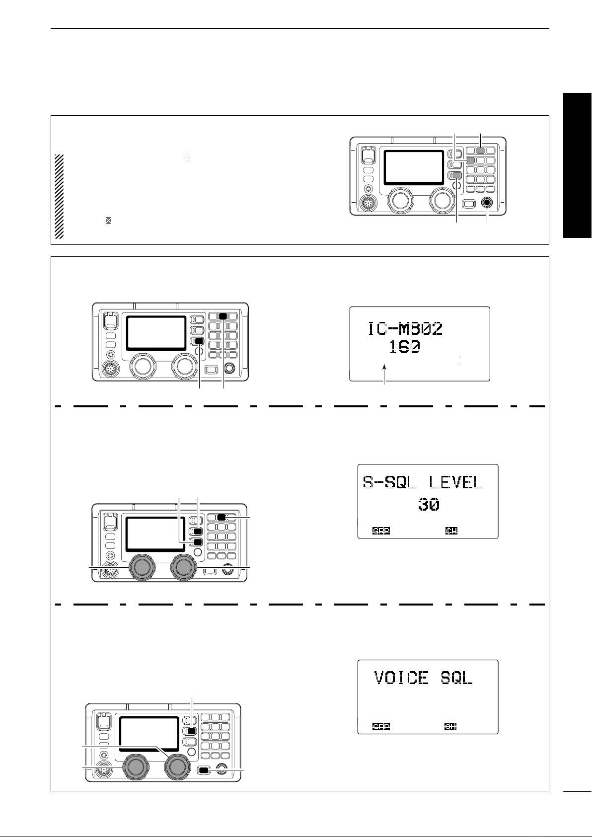
qPush [DSC] to select DSC watch mode, if neces-
sary.
wPush [MODE set] to select DSC menu, rotate
[CH] to select “All ships” then push [ENT].
eFollow the guidance displayed on the LCD (bottom
line), to set up the category, traffic frequency and
calling frequency with [CH], [ENT] and keypad.
rHold down [CANCEL/CALL] for 1 second until the
short beeps become one long beep.
tAfter an acknowledgement call is received, trans-
mit the appropriate information using voice.
•DSCequippedshipsmaymonitoryourtransmission.
FOREWORD������������� i
IMPORTANT ������������� i
EXPLICIT DEFINITIONS ������� i
PRECAUTIONS ����������� i
IN CASE OF EMERGENCY ������ii
TABLE OF CONTENTS ��������ii
QUICK REFERENCE �������iii–vii
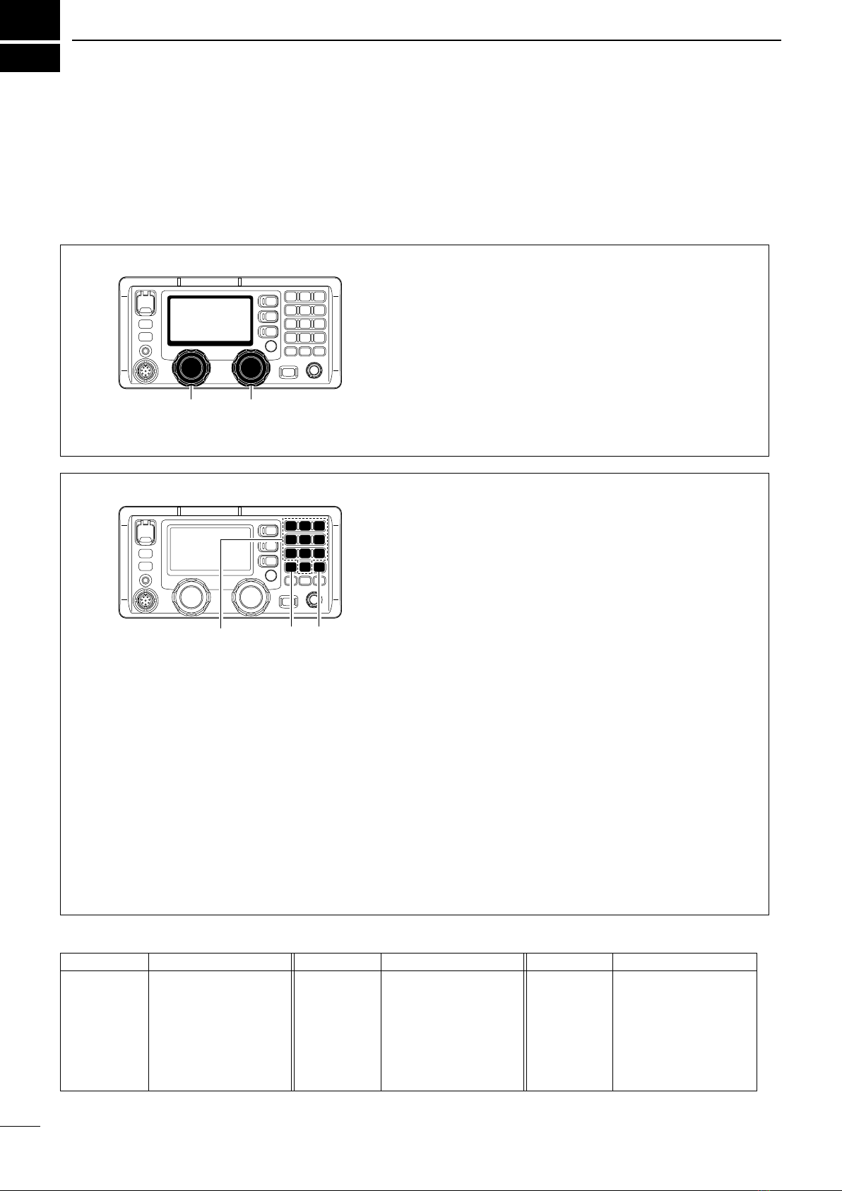
■How to set a Channel/Group��� iii
■Audio output/squelch adjustment � iv
■Basic voice transmission and reception
���������������� v
■Receiving a DSC�������� vi
■Transmitting a distress call���� vi
1 OPERATING RULES AND GUIDELINES
�����������������1
2 PANEL DESCRIPTION ����� 2–7
■Front panel— Controller������2
■Front panel— Main unit ������4
■Rear panel— Main unit ������5
■Microphone (HM-135)�������5
■LCD screen �����������6
3 SETTING A CHANNEL/FREQUENCY
��������������� 8–9
■Selecting a channel �������8
4 RECEIVE AND TRANSMIT �� 10–12
■Basic voice transmit and receive � 10
■Functions for transmit ������ 10
■Functions for receive ������ 11
■CW operation ��������� 13
■FSK operation ��������� 13
5 CHANNEL NAME PROGRAMMING 14
6 DSC PREPARATION ����� 15–16
■MMSI code programming ���� 15
■Position and time programming �16
7 CALL PROCEDURE ����� 17–38
■Distress call ���������� 17
■Distress call to ships ������ 21
■Urgency call ���������� 24
■Safety call ����������� 28
■Routine call ���������� 32
■Geographical call�������� 34
■Group call ����������� 36
■Position request call ������ 37
■Test call ������������ 38
8 WHEN RECEIVING A CALL � 39–44
■To receive a DSC call ������ 39
■Received information ������ 40
■Deleting a memory ������� 40
■Position request call ������ 41
■Distress call ���������� 41
■Distress relay call ������� 42
■Individual call ��������� 43
■Group call ����������� 44
■Geographical area call ����� 44
■Test call ������������ 44
9 MEMORY OPERATION ������ 45
■Memory description ������ 45
■Memory writing �������� 45
■Memory reading/transmitting/deleting
��������������� 45
10 DSC MENU OPERATION ��� 46–48
■General ������������ 46
■ID input ������������ 46
■Frequency input �������� 47
■Verifying self-ID �������� 48
■Memory reading/deleting ���� 48
11 E-MAIL OPERATION ������� 49
■General ������������ 49
■Operation ����������� 49
12 SET MODE ��������� 50–54
■Quick set mode �������� 50
■Initial set mode��������� 51
13 CONNECTION AND INSTALLATION
�������������� 55–64
■Supplied accessories ������ 55
■Front panel connections����� 55
■Rear panel connections ����� 56
■Ground connection ������� 57
■Power source ��������� 57
■Antenna������������ 58
■Mounting ����������� 59
■Using the optional MB-75 ���� 60
■Transceiver dimensions ����� 61
■Fuse replacement ������� 62
■Connector information ����� 63
14 SPECIFICATIONS �������� 65
15 OPTIONS ������������ 66
16 TEMPLATE ��������� 67–70
■Remote controller (RC-25)���� 67
■Speaker (SP-24) �������� 69
TABLE OF CONTENTS
1
2
3
4
5
6
7
8
9
10
11
12
13
14
15
16
Quick Reference
2001 NEW
• Available channel groups and channels
Channel No. Description Channel No. Description Channel No. Description
1 to 160
401 to 427
4-1 to 4-9
601 to 608
6-1 to 6-9
801 to 832
8-1 to 8-9
User Ch.*1
4 MHz ITU duplex Ch.
4 MHz ITU simplex Ch.
6 MHz ITU duplex Ch.
6 MHz ITU simplex Ch.
8 MHz ITU duplex Ch.
8 MHz ITU simplex Ch.
1201 to 1241
12-1 to 12-9
1601 to 1656
16-1 to 16-9
1801 to 1815
18-1 to 18-9
2201 to 2253
12 MHz ITU duplex Ch.
12 MHz ITU simplex Ch.
16 MHz ITU duplex Ch.
16 MHz ITU simplex Ch.
18 MHz ITU duplex Ch.
18 MHz ITU simplex Ch.
22 MHz ITU duplex Ch.
22-1 to 22-9
2501 to 2510
25-1 to 25-9
C1-1 to C1-21
C2-1 to C2-31
4001 to 25040
22 MHz ITU simplex Ch.
25 MHz ITU duplex Ch.
25 MHz ITU simplex Ch.
C1 channels
C2 channels
ITU FSK duplex Ch.*2
*1[GRP] changes in 20 channel steps. *2SITOR use— no group separation.
iii
QUICK REFERENCE
2001 NEW
■ How to set a Channel/Group
The IC-M802 has up to 160 user-programmable, 249
ITU SSB duplex, 124 ITU SSB simplex and 662 ITU
FSK duplex channels.
D
Using the group and channel selectors
[CH][GRP]
qRotate [GRP] to select a desired group.
 •Availablegroupsareshowninthelistbelow.
 •During user-programmable channel groupuse,the
channels change in 20-channel steps. See details on
p. 8.
Example; When starting the user-programmable Ch. 1.
1⇔21⇔41�141⇔401⇔4-1⇔601��C2-1�1
wRotate [CH] to select a desired channel.
 •Availablechannelsareshowninthelistbelow.
 •Pushing[Y]/[Z] on the microphone also selects a
channel.
D Using the keypad
Numeral keys [ENT][CE]
• When selecting an user-programmable channel
➥Push the appropriate numeral keys to set the 1,
2 or 3-digit channel number, then push [ENT].
  •Pushing[CE]clearsinputdigitsandretrievesthe
channel.
Example; When selecting Ch. 1.
Push [1 n b ] then push [ENT].
Example; When selecting Ch. 35.
Push [3 s c a n ], [5 a g c ×] then push [ENT].
Example; When selecting Ch. 128.
Push [1 n b ], [2 s q l ], [8 Mid] then push [ENT].
• When selecting an ITU duplex channel
➥Push the appropriate numeral keys to set the 3,
4 or 5-digit channel number, then push [ENT].
  •Pushing[CE]clearsinputdigitsandretrievesthe
previous channel.
Example; When selecting Ch. 401.
Push [4 s p ×], [0 d i m ], [1 n b ] then push [ENT].
Example; When selecting Ch. 2505.
Push [2 s q l ], [5 a g c ×], [0 d i m ], [5 a g c ×] then push
[ENT].
• When selecting an ITU simplex channel
➥Push the appropriate numeral keys to set the 5
or 6-digit channel number, then push [ENT].
  •Push[0d i m ] 3 times to enter “– (dash).”
  •Pushing[CE]clearsinputdigitsandretrievesthe
previous channel.
Example; When selecting Ch. 4-1.
Push [4 s p ×], [0 dim], [0 dim], [0 dim], [1 n b ] then
push [ENT].
- After pushing [0 d i m ] 3 times, “–” appears.
Example; When selecting Ch. 25-2.
Push [2 sql], [5 a g c ×], [0 dim], [0 dim], [0 dim],
[2 s q l ] then push [ENT].
- After pushing [0 d i m ] 3 times, “–” appears.
2001 NEW
Quick Reference
iv
QUICK REFERENCE
■ Audio output/squelch adjustment
D Audio output level
➥Rotate [VOL] to adjust audio output level.
NOTE: Make sure that no “
SP
” and “SQL” indica-
tors are displayed during audio level adjustment,
otherwise, audio may not be output.
If either or both indicators are displayed, perform
the following operations;
- When “
SP
” is displayed, push [F] then [4 s p ×].
-
When “SQL” is displayed, push [F] then [2 s q l ].
[VOL]
[2
SQL
][4
SP
×]
[F]
D Squelch function
➥Push [F] then [2 s q l ] to turn the squelch function
ON or OFF.
[2
SQL
][F]
“SQL” appears when the squelch function is ON.
SQL
LH
CH
---GPS---
Lat
45
59'N
Lon134
44'E
16:23
USB SIMP
• Squelch level adjustment
qPush [F] then [2 s q l ] to turn ON the squelch func-
tion.
 •Firstselectthedesiredfrequencyorchannel.
wPush [F] then [MODE s e t ] to enter the quick set
mode.
[MODE
SET
]
[2
SQL
]
[CH]
[GRP]
[F]
eRotate [GRP] to select the “S-SQL LEVEL” item.
rRotate [CH] to adjust the squelch level.
 •Adjusttheleveltobetween1and100.
ITEM SEL
tPush [MODE s e t ] to exit the quick set mode.
• Voice squelch function
The voice squelch function detects voice components
in the received signal and opens the squelch only
when voice components are included in the signal.
qWhile holding down [MODE set], turn ON the
power to enter the initial set mode.
[MODE SET]
[POWER]
[GRP]
[CH]
wRotate [GRP] to select the “VOICE SQL” item.
eRotate [CH] to turn the voice squelch function ON
or OFF
***
SET
MODE
***
OFF
ON
ÇÇ
ITEM SEL
rTurn the power OFF then ON again to exit the ini-
tial set mode.
1-1-32 Kamiminami, Hirano-ku, Osaka 547-0003, Japan
A-7096H-1US
Printed in Japan
© 2013 Icom Inc.
2001 NEW

Other manuals for IC-M802

9

Other Icom Transceiver manuals

Icom IC-211E User manual

Icom

Icom IC-211E User manual

Icom IC-A210 User manual

Icom

Icom IC-A210 User manual

Icom IC-2GA User manual

Icom

Icom IC-2GA User manual

Icom DC-197 Installation and operating instructions

Icom

Icom DC-197 Installation and operating instructions

Icom IC-7100 User manual

Icom

Icom IC-7100 User manual

Icom IC-228A User manual

Icom

Icom IC-228A User manual

Icom IC-400BB User manual

Icom

Icom IC-400BB User manual

Icom IC-F4261DT User manual

Icom

Icom IC-F4261DT User manual

Icom IC-M35 User manual

Icom

Icom IC-M35 User manual

Icom ID-31A PLUS Setup guide

Icom

Icom ID-31A PLUS Setup guide

Icom IC-F621 User manual

Icom

Icom IC-F621 User manual

Icom IC-F27SR User manual

Icom

Icom IC-F27SR User manual

Icom IC-4008A User manual

Icom

Icom IC-4008A User manual

Icom IC-F5011 User manual

Icom

Icom IC-F5011 User manual

Icom IC-7300 User manual

Icom

Icom IC-7300 User manual

Icom IC-M73EURO User manual

Icom

Icom IC-M73EURO User manual

Icom IC-A110 User manual

Icom

Icom IC-A110 User manual

Icom IC-M710 User manual

Icom

Icom IC-M710 User manual

Icom D-STAR ID-4100A User manual

Icom

Icom D-STAR ID-4100A User manual

Icom IFC-30LT User manual

Icom

Icom IFC-30LT User manual

Icom IC-F610 User manual

Icom

Icom IC-F610 User manual

Icom IC-F3062T User manual

Icom

Icom IC-F3062T User manual

Icom IC-120 User manual

Icom

Icom IC-120 User manual

Icom IC-M710RT User manual

Icom

Icom IC-M710RT User manual

Popular Transceiver manuals by other brands

ELECRAFT K3EXREF Installation and operation

ELECRAFT

ELECRAFT K3EXREF Installation and operation

Yaesu FT-290R II operating manual

Yaesu

Yaesu FT-290R II operating manual

Yaesu FT1DR instruction manual

Yaesu

Yaesu FT1DR instruction manual

evertz 7700 MultiFrame manual

evertz

evertz 7700 MultiFrame manual

Iridium 9601 Product Developer Guide

Iridium

Iridium 9601 Product Developer Guide

Vcom IduBST1918 Installation and operation guide

Vcom

Vcom IduBST1918 Installation and operation guide

Aurora IPX series user guide

Aurora

Aurora IPX series user guide

PRESIDENT Barry FM owner's manual

PRESIDENT

PRESIDENT Barry FM owner's manual

Sommerkamp TS-780DX instruction manual

Sommerkamp

Sommerkamp TS-780DX instruction manual

uAvionix SkyEcho ATT-20B Installation and Pilot's Guide

uAvionix

uAvionix SkyEcho ATT-20B Installation and Pilot's Guide

Yaesu FTDX 9000 Series Operation manual

Yaesu

Yaesu FTDX 9000 Series Operation manual

Allied Telesis CentreCOM AT-810SL user manual

Allied Telesis

Allied Telesis CentreCOM AT-810SL user manual

Yaesu Mark-V FT-1000MP installation instructions

Yaesu

Yaesu Mark-V FT-1000MP installation instructions

ATS 1225 Technical manual

ATS

ATS 1225 Technical manual

Transition Networks ETHERNET E- FL/RED-MC01(SMA) user guide

Transition Networks

Transition Networks ETHERNET E- FL/RED-MC01(SMA) user guide

Garmin GDR 66 Installatioin manual

Garmin

Garmin GDR 66 Installatioin manual

Uniden UH8050S owner's manual

Uniden

Uniden UH8050S owner's manual

Yaesu FT-8800R operating manual

Yaesu

Yaesu FT-8800R operating manual

manuals.online logo
manuals.online logoBrands
  • About & Mission
  • Contact us
  • Privacy Policy
  • Terms and Conditions

Copyright 2025 Manuals.Online. All Rights Reserved.