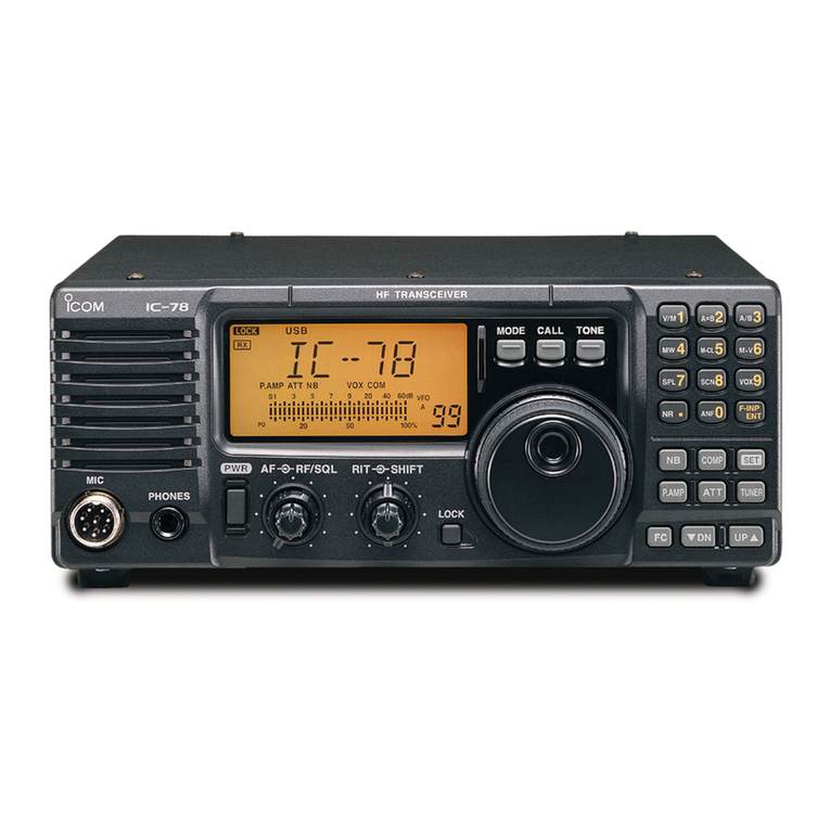
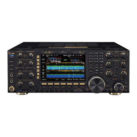
Icom IC-725 User manual

?COM
INSTRUCTION MANUAL
HF ALL BAND TRANSCEIVER
IC-725
loom Inc.

CAUTIONS INTRODUCTION
(1) Before using the IC-725, read all instructions carefully
and completely.
(2) SAVE THIS INSTRUCTION MANUAL -This instruc-
tion manual contains important safety and operating
instructions for the IC-725.
(3) NEVER connect the DC power cable to an AC outlet.
This will ruin the transceiver.
(4) NEVER apply more than 16 V DC to the DC POWER
SOCKET on the transceiver rear panel. Check the
power source voltage before connecting the power
cable.
Icom's new IC-725 HF ALL BAND TRANSCEIVER is
designed to meet the increasing demand of today's amateur
radio users for transceivers with fewer controls and switches,
especially for hands-free mobile operation.
The IC-725 has the following advanced features:
•DDS (Direct Digital Synthesizer)
_«26 user-programmable memory channels
•3 scan types
•Selectable tuning rate in 10, 20 or 50 Hz steps
•Band stacking register capability
•10 dB preamplifier
•20 dB' attenuator
(5) NEVER allow children to touch the transceiver during
operation.
(6) NEVER expose the transceiver to rain, snow or any
liquid.
(7) AVOID using or storing the transceiver in temperatures
below -10°C (+14°F) or over +60°C (+150°F).
To thoroughly understand the capabilities of your new
IC-725, please read this manual carefully before attempting
operation. If you have any questions regarding the opera-
tion of the IC-725, feel free to contact your nearest
authorized Icom Dealer or Service Center.
OPERATING CAUTIONS UNPACKING
(1) In any mobile operation, DO NOT operate the trans-
ceiver without running the vehicle's engine. The
vehicle's battery will quickly run out if the transceiver
power is ON while your vehicle's engine is OFF.
(2) In maritime mobile operation, keep interconnection
cables as far away as possible from electronic instru-
ments to prevent instrument malfunctions.
(3) BE CAREFUL! If the transceiver is not securely
mounted with bolts and nuts, personal injury or
transceiver damage could occur due to braking, wave
shock, vibrations, etc.
(4) AVOID using the transceiver in excessively dusty
environments.
(5) AVOID placing the transceiver in direct sunlight.
(6) BE CAREFUL! The heatsink may become hot when
operating the transceiver continuously for long periods.
(7) Transmitting without an antenna may damage the
transceiver.
Accessories included with the IC-725: Qty.
©DC power cable (OPC-025A) 1
@Hand microphone (HM-1 2) 1
<D Spare fuse (20 A) 1
®Spare fuse (4 A) 1
(D Screws B1 4x12 CR (for optional MB-23 installation) .... 2
©Screws CO 3x6(for optional MB-23 installation) 4
TABLE OF CONTENTS
CAUTIONS
OPERATING CAUTIONS
INTRODUCTION. .
UNPACKING
TABLE OF CONTENTS.
1. CONTROL FUNCTIONS 1-4
1-1FRONT PANEL. 1
1-2REAR PANEL.- 3
1-3 MICROPHONE (HM-12) 3
1- 4FUNCTION DISPLAY 4
2. INSTALLATION ..5-6
2- 1UNPACKING 5
2-2 MOUNTING THE TRANSCEIVER 5
2-3 ANTENNA 5
2-4 GROUNDING 5
2-5 WIRING THE DC POWER CABLE 5
2- 6REAR PANEL CONNECTIONS 6
3. SYSTEM INTERCONNECTIONS 7-12
3- 1POWER SUPPLY CONNECTIONS 7
3-2 LINEAR AMPLIFIER CONNECTIONS. .8
3-3ANTENNA TUNER CONNECTIONS ... 9
3-4 AH-3 OPERATING PROCEDURES .... 10
3-5 AFSK TERMINAL UNIT
CONNECTION 10
3-6 MIC CONNECTOR INFORMATION 10
3- 7ACC SOCKET INFORMATION 11
3-8 REMOTE JACK (CI V)
INFORMATION 12
4. PRE-OPERATION 13-16
4- 1INITIAL SETTINGS 13
4-2 FREQUENCY SELECTION 13
4-3VFO AAND VFO BSELECTION .... 14
4-4 RECEIVER CONTROLS
AND SWITCHES 15
4- 5TRANSMITTER CONTROLS
AND SWITCH 16
5. BASIC OPERATION 17-21
5- 1SSB OPERATION 17
5-2 CW OPERATION 18
5-3 AM OPERATION 19
5-4 FM OPERATION 20
5-5 RIT/Af FUNCTION 21
5-6 SPLIT OPERATION 21
6. MEMORY CHANNEL OPERATION .... 22
6-1 VFO AND MEMORY MODE
SELECTION 22
6-2 MEMORY CHANNEL SELECTION 22
6-3 MEMORY WRITING 22
6- 4FREQUENCY TRANSFERRING
[M VFO] v..22
7. SCANNING OPERATION 23
7-1SCAN TYPES 23
7- 2PROGRAMMED SCAN 23
7-3MEMORY SCAN 23
7-4 SELECTED MODE MEMORY SCAN. . . 23
7- 5SUPPLEMENTAL SCAN SETTINGS ... 23
8. MAINTENANCE AND
ADJUSTMENT 24-28
8- 1DISASSEMBLING THE
TRANSCEIVER
.
24
8-2 FUSE REPLACEMENT 25
8-3 CPU RESETTING 25
8-4 CPU BACKUP BATTERY 25
8-5 CLEANING 25
8-6 TROUBLESHOOTING .*26
8- 7ADJUSTMENTS 27
9. INSTALLATION OF OPTIONS 29-30
9- 1UI-7 AM •FM UNIT 29
9-2 UT-30 PROGRAMMABLE TONE
ENCODER UNIT 29
9-3 CW NARROW FILTERS 29
9-4 CR-64 HIGH-STABILITY CRYSTAL
UNIT 30
9- 5MB-23 CARRYING HANDLE 30
10. INSIDE VIEWS 31-32
10- 1MAIN UNIT 31
10-2 PLL UNIT 32
11. BLOCK DIAGRAM 33
12. SPECIFICATIONS 34
13. OPTIONS 35-36
SCHEMATIC DIAGRAM SEPARATE
ii

1CONTROL FUNCTIONS
1-1 FRONT PANEL (D <D
AF-§>-SQL MIC -§>- RF PWR
(D RECEIVE INDICATOR
Indicates that the squelch is open.
(D TRANSMIT/ALC INDICATOR (p. 16)
Lights when the transceiver is transmitting.
©METER
Shows the strength of areceived signal and relative
output power while transmitting.
@VFO SWITCH [VFO] (pgs. 14, 22)
Selects VFO Aor VFO Bfor tuning purposes.
©SPLIT SWITCH [SPLIT] (p. 21)
Selects split operation.
©MEMORY CHANNEL UP/DOWN SWITCHES [UP]
[DOWN] (p. 22)
Changes memory channels.
(7) MEMORY WRITE SWITCH [MW] (p. 22)
Stores the displayed frequency and mode into the
displayed memory channel.
®MEMORY READ SWITCH [MEMO] (p. 22)
Selects MEMORY CHANNEL mode.
©RIT SWITCH [RIT] (pgs. 15,21)
Turns ON and OFF the RIT circuit.
>RIT CONTROL (pgs. 15,21)
Shifts the receive frequency when the RIT function is
ON.
)FUNCTION SWITCH [FUNC]
Activates the secondary switch functions.
SWITCH FUNCTION
[FUNC] +[VFO] Activates programmed scan. (p. 23)
[FUNC] +[SPLIT] Equalizes the frequency and mode
of operation of the two VFOs.
[FUNC] +[MEMO] Activates memory scan. (p. 23)
[FUNC] +[MW] Activates the frequency transfer
function, (p. 22)
[FUNC] +[RIT] Adds the RIT shift frequency to the
displayed frequency, (p. 21
)
[FUNC] +[TUNER] Bypasses the AH-3 HF AUTO-
MATIC ANTENNA TUNER
(optional), (p. 10)
[FUNC] +[kHz]
[FUNC] +[BAND]
Changes the tuning step. (p. 14)
Turns ON and OFF the 10 Hz digit
on the frequency display, (p. 14)
[FUNC] +[ LOCK]
+[MEMO] Activates the mode selected me-
mory scan. (p. 23)
©ANTENNA TUNER SWITCH [TUNER] (p. 10)
Tunes the AH-3 HF AUTOMATIC ANTENNA TUNER
(optional).
(0) BAND SWITCH [BAND] (p. 13)
Allows the MAIN DIAL to select bands only.

CONTROL FUNCTIONS -|
See Section 1-4FUNCTION DISPLAY
inn mMEMO
r/c
IUU.UU split LU
HF TRANSCEIVER 10725
VFO SPLIT UP
fpTsCAN||A=B
|M. SCAN] [M-VFO~]
M-CH
MEMO MW DOWN
VFO SPLIT
|P. SCAN |IA=B|
|m.scan|
MEMO MW
(!)
UP
M-CH
DOWN*
(M) DIAL LOCK SWITCH [LOCK]
Deactivates the MAIN DIAL and transmits asubaudible
tone signal in FM mode.
(I5) MHz TUNING RATE SWITCH [MHz] (p. 14)
Sets the tuning steps at 1MHz.
(0) kHz TUNING RATE SWITCH [kHz] (p. 14)
Sets the tuning rate for 1kHz steps.
©MAIN DIAL
Changes the displayed frequency.
(f|) BRAKE ADJUSTMENT SCREW (p. 27)
Adjusts MAIN DIAL tension.
C\J> MODE SWITCHES (pgs. 17-20)
Selects the desired operating mode.
@AGC SWITCH [AGC] (p. 15)
Changes the time constant of the AGC circuit.
(2j) PREAMP SWITCH [PRE] (p. 15)
Activates the built-in 10 dB gain RF preamplifier.
(22) ATTENUATOR SWITCH [ATT] (p. 15)
Activates the 20 dB attenuator to prevent front end
overload.
(23) NOISE BLANKER SWITCH [NB] (p. 15)
Activates the noise blanker circuit.
(24) MIC CONNECTOR [MIC] (p. 10)
Accepts Icom hand or desk microphones. Refer to
Section 13 OPTIONS.
(25) RF POWER CONTROL [RF PWR] (p. 16)
Adjusts RF output power.
(26) MIC GAIN CONTROL [MIC] (p. 16)
Adjusts microphone input gain.
@SQUELCH CONTROL [SQL] (p. 15)
Adjusts the squelch threshold level.
(28) AF GAIN CONTROL [AF] (p. 15)
Adjusts audio output level.
(29) HEADPHONES JACK [PHONE]
Accepts astandard 1/4 inch plug from 4~16 £1 mono
or stereo headphones.
(30) TRANSMIT/RECEIVE SWITCH [TRANSMIT]
Selects transmit or receive.
(31) POWER SWITCH [POWER]
Turns the power ON and OFF.

-J CONTROL FUNCTIONS
1-2 REAR PANEL
UULi
®
uu
DO
ANT
©© DC 13 8V
REMOTE StS
ICOM LCJJ25.
SEIUIM
EXT SP BK IN—DELAY KEY ACCI2I ACC(I) ALC SEND
®<§ «®®®
©ft ooee V. .
Ina-
\\5J £?/// VVv^TPv/ a
@ANTENNA CONNECTOR (pgs. 5, 6)
Connects a50 £2 antenna with aPL-259 plug.
(§) CI VREMOTE CONTROL JACK (p. 12)
Designed for use with apersonal computer for remote
operation of transceiver functions.
(3J) DC POWER SOCKET (p. 7)
Accepts 13.8 VDC using the supplied DC cable.
(35) TUNER CONTROL SOCKET (p. 9)
Accepts the optional AH-3 HF AUTOMATIC ANTEN-
NA TUNER control cable.
®SEND CONTROL JACK (p. 8)
Goes to ground when transmitting to control an external
unit.
@ALC INPUT JACK (p. 8)
Connects to the ALC output jack of anon-lcom linear
amplifier.
(§) ACCESSORY SOCKETS (p. 11)
Input and output connections for external equipment.
(§) CW KEY JACK (pgs. 6, 18)
Accepts astraight key or electronic keyer with astan-
dard 1/4 inch 3-conductor plug.
@CW BREAK-IN DELAY CONTROL (p. 18)
Adjusts the transmit-to-receive switching delay time for
CW semi break-in operation.
@CW SEMI BREAK-IN SWITCH (p. 18)
Turns ON and OFF the CW semi break-in operation.
(42) EXTERNAL SPEAKER JACK (p. 6)
Connect a4~16 £2 speaker here, if required.
@GROUND TERMINAL (pgs. 5, 6)
To prevent electrical shocks, TVI, BCI and other prob-
lems, connect this terminal to ground.
1-3 MICROPHONE (HM-12)
<B> UP/DOWN SWITCHES
Changes the operating frequency or memory channel.
Push and hold either of these switches to change the
frequency or memory channel continuously.
©PTT SWITCH
Push to transmit.
<© UP/DOWN ON/OFF SWITCH
Prevents accidental changes of the [UP] and [DN]
switches.

CONTROL FUNCTIONS -j
1-4 FUNCTION DISPLAY
©©© © ©
IscANj'LSBUSBCW-NAMFM'lHiilFUNC^'MEMO'
jvfoa —ir
IV FO B.—'.S
SPLIT iL U
{TUNE |C|—/—#—#ZIC
[thIu], 1I.L -1 1-1- -f
®(5|) ©© © ©
©SCAN INDICATOR "SCAN" (p. 23)
Lights when scan is operating.
©MODE INDICATORS
Indicates the operating mode.
©RIT INDICATORS "RIT" (p. 21)
Lights when the RIT function is turned ON.
©FUNCTION INDICATOR "FUNC"
Lights when the [FUNC] switch is pushed.
©MEMORY INDICATOR "MEMO" (p. 22)
Lights when MEMORY mode is selected.
©MEMORY CHANNEL INDICATOR (p. 22)
Shows memory channel numbers.
©VFO INDICATORS "VFO A" "VFO B" (p. 14)
Indicate aVFO mode.
©FREQUENCY DISPLAY
Displays the operating frequency.
©THROUGH INDICATOR 'THRU" (p. 10)
Lights when the AH-3 HF AUTOMATIC ANTENNA
TUNER (optional) is bypassed.
©TUNING INDICATOR "TUNE" (p. 10)
Lights when the AH-3 HF AUTOMATIC ANTENNA
TUNER (optional) is being tuned.
©TUNING DIGIT INDICATORS "—"(pgs. 13, 14)
Points to the lowest digit changed when the MAIN
DIAL is rotated.
©SPLIT INDICATOR "SPLIT" (p. 21)
Lights when split operation is being used.

2INSTALLATION
2-1 UNPACKING 2-3 ANTENNA
After unpacking, immediately describe any damage to the
delivering carrier or dealer. Keep the shipping cartons. For
adescription and adiagram of accessory equipment in-
cluded with the IC-725, see UNPACKING on the inside
front cover.
2-2 MOUNTING THE TRANSCEIVER
Select alocation for the transceiver that allows adequate air
circulation and access to the front and rear panels. Do not
place in areas subject to extr-eme heat, cold, or vibrations,
or near TV sets, radios and electro-magnetic sources.
For mobile installations, an optional IC-MB5 MOBILE
MOUNTING BRACKET is available.. Select alocation
which can support the weight of the transceiver and does
not interfere with the operation of the vehicle.
•ADJUSTABLE ANGLES
The stand on the bottom of the IC-725 gives the
transceiver two selectable angles.
Select an antenna, such as a well-matched 50 12 antenna
and feedline. The transmission line should be acoaxial
cable. VSWR should be less than 1.5:1.
CAUTION: Protect your transceiver from lightning by
using alightning arrestor.
2-4 GROUNDING
To prevent electrical shocks, TVI, BCI and other problems,
ground the transceiver through the GROUND terminal on
the rear panel.
For best results, connect aheavy gauge wire or strap to a
long earth-sunk copper rod. Make the distance between the
GROUND terminal and ground as short as possible.
2-5 WIRING THE DC POWER CABLE
Insert arubber grommet to the DC power cable to prevent
shorting.
PL-259 CONNECTOR INSTALLATION
Solder
1)Slide the coupling ring over the coaxial cable.
2) Strip the cable as shown in the diagram, and soft
solder the center conductor.
3) Slide the connector body onto the cable and solder.
4) Screw the coupling ring onto the connector body.
1inch =25.4 mm

INSTALLATION 2
2-6 REAR PANEL CONNECTIONS
ANTENNA CONNECTOR
•Dipole antenna
\
•Yagi beam antenna
GROUND TERMINAL
The transceiver MUST
be grounded through
this terminal.
CI VREMOTE CONTROL JACK
Transceive function connec- Computer control connection
tion with another Icom. HF through aCT-1 7Cl-V LEVEL
transceiver or receiver. CONVERTER (optional).
CZ3
©yii io
o:
a
o
O
PS-55 AC POWER SUPPLY
See p. 7for connections.
XT
5
SP-7 EXTERNAL SPEAKER
Height and design
are matched with
the IC-725.
KEY JACK
Straight key or external electronic keyer
connection.
2-conductor phone plug can also be used.
ACC
SOCKETS
Seep. 11
ALC/SEND
JACKS
See p. 8
AH-3 HF AUTOMATIC ANTENNA TUNER
^See pgs. 9and 10 for details.
AH-2b
ANTENNA ELEMENT KIT
(sold separately)

3SYSTEM INTERCONNECTIONS
3-1 POWER SUPPLY CONNECTIONS
Use the PS-55 AC POWER SUPPLY (sold separately)
when operating the IC-725 with AC power. Refer to the
diagram below.
The [POWER] switch on the IC-725 front panel synchro-
nizes the PS-55 with the IC-725.
CAUTION: Before connecting the DC power cable,
check the following important items. Make
sure:
•The [POWER] switch is OFF.
•Output voltage of the power source is
12 ~15 Vwhen you want to use anon-
Icom power supply.
•DC power cable polarity is correct,
red positive (+) terminal
black -» negative {—)terminal
•CONNECTING THE PS-55
IC-725
<2> )(3 [s=^n;
onoooO00
-l_r
The [POWER] switch synchronizes
the PS-55 AC POWER SUPPLY
with the IC-725.
PS-55
DC POWER
SOCKET
O
AC OUTLET
(u)
•CONNECTING ANON-ICOM AC POWER SUPPLY
IC-725
o
oDoOoO00
(J AC OUTLET
Use the supplied
DC power cable

SYSTEM INTERCONNECTIONS
3-2 LINEAR AMPLIFIER CONNECTIONS
To connect the IC-2KL LINEAR AMPLIFIER or alinear
amplifier not made by Icom, refer to the diagram below.
The optional IC-2KL HF LINEAR AMPLIFIER may be
easily connected to the IC-725. OPC-1 18 (sold separately)
is necessary.
When connecting the transceiver to anon-lcom linear
amplifier, connect the cables as shown in the diagram below.
-The specification for the keying relay is DC 16 V, 2A
maximum.
If the linear amplifier requires greater voltage than the
above value, alarge relay must be installed between the
amplifier and the transceiver.
•CONNECTING THE IC-2KL
ACC CABLE
(Supplied with IC-2KL)
To ANTENNA
OPC-1 18
(Sold separately)
•CONNECTING ANON-ICOM LINEAR AMPLIFIER
To ANTENNA 50 ft COAXIAL CABLE
IC-725
ORF INPUT
O
RF OUTPUT
ALCO
SENDO
O- lilluuiiyuut
I>l £
j6ooo O 00
ALC^ ASEND

3SYSTEM INTERCONNECTIONS
3-3 ANTENNA TUNER CONNECTIONS
It is recommended that an Icom antenna tuner be used
between the IC-725 and the antenna system for maximum
transceiver performance.
Refer to the instruction manuals of each antenna tuner
below for more detailed connecting and operating infor-
mation.
When connecting the IC-725 to the IC-AT500 or IC-AT100,
the optional OPC-118 INTERFACE CABLE is necessary.
•CONNECTING THE IC-AT500
COAXIAL CABLE
(Supplied with IC-AT500)
To
ANTENNA
IC-AT500 QQ
ACC CABLE
(Supplied [|
with
IC-AT500) £
ACC CABLE
(Supplied with IC-2KL)
QIC-2KL
P1U
To IC-2KLPS
GROUND
COAXIAL CABLE
(Supplied with IC-2KL)
IC-725
IIUl II
j__
OaOOoo oo [
OPC-118
J(Sold separately)
•CONNECTING THE AT-150
COAXIAL CABLE
To ANTENNA (Supplied with AT-1 50)
IC-725
CONTROL CABLE
(Supplied with AT-1 50)
—GROUND
•CONNECTING THE AH-3 OR AH-2
To ANTENNA
ELEMENT

SYSTEM INTERCONNECTIONS
3-4 AH-3 OPERATING PROCEDURES
The AH-3 HF AUTOMATIC ANTENNA TUNER is
designed for use with the IC-725. By pushing the [TUNER]
switch on the IC-725 front panel, the AH-3 tunes at 50 £2
on 1.8 MHz ~30 MHz with alength of 12m(40 ft) wire.
The AH-2a HF AUTOMATIC ANTENNA TUNER can be
used with the IC-725 without the supplied CONTROLLER
UNIT.
Following are the simple operation procedures for using the
AH-3 HF AUTOMATIC ANTENNA TUNER:
1)Connect cables from the AH-3 and antenna wire as
shown in the diagram on p. 9.
2) Turn transceiver power ON.
3) Select the desired band and frequency.
-4) Push the [TUNER] switch.
•"TUNE" flashes on the FUNCTION DISPLAY.
•The AH-3 automatically tunes at 50 £1.
5) "TUNE" steadily appears when the AH-3 tunes at 50 £2.
6) "THRU" appears when the AH-3 cannot tune at 50 £2.
•When "THRU" appears, the AH-3 is bypassed and the
antenna wire is connected to the antenna connector on
the IC-725 directly.
7) When you want to bypass the AH-3 manually, push the
[FUNC] switch then push the [TUNER] switch.
•"THRU" appears on the FUNCTION DISPLAY.
3-5 AFSK TERMINAL UNIT
CONNECTION See p-11 for ACC(1>and MIC connector pin
information.
When operating an AFSK such as RTTY, AMTOR or packet,
connect external equipment to the ACC(1) SOCKET on the
rear panel or MIC CONNECTOR on the front panel as in
the following diagram below.
Using the ACC(1) SOCKET
(Rear panel view)
Using the MIC CONNECTOR
(Front panel view)
AFSK output
"1
AF input
SQUELCH input
PTT
Ground (GND)
AFSK TERMINAL UNIT
3-6 MIC CONNECTOR INFORMATION
(Front panel view)
©MIC INPUT-
)+8V DC_
OUTPUT
)FREQ
UP/DOWN
)AF OUTPUT
®GND
microphone ground)
©GND
(PTT ground)
)PTT
(4) SQUELCH SWITCH
PIN NO. FUNCTION DESCRIPTION
2+8 VDC output Max. 10 mA
3Frequency up Ground
Frequency down Ground through 470 £2
4Squelch open "LOW" level
Squelch closed "HIGH" level
CAUTION: DO NOT short pin 2to ground as this can
damage the internal 8Vregulator.

3SYSTEM INTERCONNECTIONS
•HM-12 SCHEMATIC DIAGRAM
MICROPHONE MICROPHONE CABLE MICRPHONE PLUG
3-7 ACC SOCKET INFORMATION
(1) ACC(1). SOCKET
PIN NO. PIN NAME DESCRIPTION SPECIFICATIONS
1NC No connection.
2GND Connects to ground. Connected in parallel with ACC(2) pin 2.
3SEND Input/output pin.
Goes to ground when transmitting.
When grounded, transmits.
Ground level :-0.5 ~0.8 V
Input current less than 20 mA
Connected in parallel with ACC(2) pin 3.
4MOD Modulator input.
Connects to amodulator.
Input impedance
Input level
:10 kft
:Approx. 100 mV rms
5AF AF detector output.
Fixed, regardless of [AF] position.
Output impedance
Output level
:4.7 kfi
:100 ~300 mV rms
6SOLS Squelch output.
Goes to ground when squelch opens.
SQL open
SQL closed
:Less than 0.3 V/5 mA
:More than 6.0 V/1 00 fiA
713.8 V13.8 Voutput when power is ON. Output current :Max. 1A
Connected in parallel with ACC(2) pin 7.
8ALC ALC voltage input.
Control voltage :-4 ~V
Input impedance :More than 10 k£2
Connected in parallel with ACC(2) pin 5.
(2) ACC(2) SOCKET
PIN NO, PIN NAME DESCRIPTION SPECIFICATIONS
18VRegulated 8Voutput. Output voltage
Output current
:8V+0.3V
Less than 10 mA
2GND Same as ACC(1) pin 2.
3SEND Same as ACC(1) pin 3.
4BAND Band voltage output.
(Varies with amateur band) Output voltage :0-8.0V
5ALC Same as ACC(1) pin 8.
6NC No connection.
713.8 VSame as ACC(1) pin 7.

SYSTEM INTERCONNECTIONS
3-8 REMOTE JACK (Cl-V)
INFORMATION
The IC-725 can be connected through aCT-17CI-V LEVEL
CONVERTER (optional) to apersonal computer equipped
with an RS-232C port. Icom Communication Interface -V
(Cl-V) controls frequency, mode, memory channels, etc.
•CT-17 CONNECTION
Up to four Icom Cl-V transceivers can be connected
to apersonal computer equipped with as RS-232C
port.
AC outlet
Personal
computer
Cl-V bus line
(1) Cl-V CONDITION
Transmitters and receivers using the Icom Cl-V System
exchange serial information in the packet format. The
contents of adata packet can be changed by diodes D2 ~
D4, D57 ~D63 and D64 on the MAIN UNIT. See diagram
at right below for the location of these diodes.
•Baud rate
Baud rate is the data transfer rate. The standard Icom Cl-V
baud rate is 1200 bps.
BAUD RATE
(bps)
DIODE
D2 D3
9600 Insert diode
1200 Insert diode
300 Insert diode Insert diode
|:Default
•Frequency data
When connecting the transceiver with the IC-735, change
the value to 4bytes.
FREQUENCY DATA DIODE (D4)
4bytes No diode (Cut D4)
5bytes Insert diode
Default
•Address
You can set an independent address for your IC-725. The
IC-725 has the address of 28H (40) as a default value.
Figures marked with an Hare hexidecimals and bracketed
figures ()are decimals.
DIODE
D57
(1)
D58
(2)
D59
(4)
D60
(8)
D61
(16)
D62
(32)
D63
(64)
Insert
diode Insert
diode
Default 28H (40)
•Transceive
Transceive operation is possible using the IC-725 with
another transceiver such as the IC-781. Either transceiver
can be used as the transmitter or receiver.
TRANSCEIVE DIODE (D64)
ON Insert diode
OFF No diode (Cut D64)
Default
(2) DIODE LOCATION
Diodes are located on the PLL UNIT as shown in the
diagram below.
See p. 24 for transceiver disassembly information.
•Magnification of the diode location
c
©4BAUD <§)02
@CD-®D3
@CD-®D4
©d>Q05
mmirtcDeococDco
Front panel side

4PRE-OPERATION
4-1 INITIAL SETTINGS
NOTE: Follow all instructions in Section 3before
operating the transceiver.
Turn the [POWER] switch OFF before connecting the DC
power cable to the DC power socket on the rear panel.
Set switches and controls as shown in the table below.
SWITCH POSITION SWITCH POSITION
POWER OUT LOCK OUT
TRANSMIT OUT AF CCW
NB OUT SQL CCW
ATT OUT MIC CENTER
PRE OUT RF PWR CW
AGC OUT
CW: Clockwise CCW: Counterclockwise
4-2 FREQUENCY SELECTION
(1) BAND SELECTION
The IC-725 covers all HF amateur bands from 1.9 MHz ~
28 MHz for transmitting and has receive capability from
500 kHz ~30 MHz. The IC-725 has aconvenient band
stacking register function (see below).
1) Push the [BAND] switch.
•Two appear above the digits that can be changed.
Two ^sappear.
r1
CW
inin nn vfoa oc
1.U IU.UU CO
2) Rotate the MAIN DIAL to select the desired amateur
band.
•To select the desired operating frequency, see (2)
OPERATING FREQUENCY SELECTION on the next
page.
•Band changes occur as shown in the following diagram.
These digits change.
nCW
in in nn vfoa zic
IjU IU.UU LU
BAND STACKING REGISTER SIMULATION
GENERAL COVERAGE NOTE:
As shown in the diagram above, the general coverage
band (Gene) can be used between any amateur band.
The transceiver memorizes the previously used frequency
in the band stacking register cycle.
3) Push the [BAND] switch again to cancel the [BAND]
switch function.
-Two "^"s disappear.
CW
Zi inin nn VF0A zic
LLU IU.UU CO
Tech Talk from Icom
Q. What is the function of the band stacking register?
A. The band stacking register stores operating fre-
quencies in VFO modes, switches bands, and
returns the transceiver to stored frequencies.
This is especially convenient when switching bands
during contests and for quick monitoring of pro-
pagation conditions on other bands.
BAND STACKING REGISTER EXAMPLE
Each band stores the last used frequency and mode.
BAND
c* I.c?50.00 c*5
(21 MHz band)
The displayed fre-
quency is kept until
new information is
input.
^8.580.00"OA ^S
(28 MHz band)

PRE-OPERATION 4
(2) OPERATING FREQUENCY SELECTION
1) To select the desired operating band, see (1) BAND
SELECTION on the previous page.
2) Rotate the MAIN DIAL to set the desired operating
frequency.
•The frequency changes in 10 Hz steps.
•To change the frequency either in 20 Hz or 50 Hz
steps, see (3) CHANGING THE FREQUENCY STEP.
•To change the frequency quickly, see step 3.
•Faster MAIN DIAL rotation automatically shifts the
tuning increment by 10 kHz per full rotation.
2) Push and hold the [kHz] switch, then rotate the MAIN
DIAL
•The FUNCTION DISPLAY shows frequency steps for
10 Hz, 20 Hz and 50 Hz sequentially.
USB zm
.LU. VFO Afl
O
3) Select the desired frequency step and release the [kHz]
switch.
When the [kHz] switch is pushed, 'W appears
above the kHz digit. Rotating the MAIN DIAL
changes the kHz digit.
-Push [kHz].
TjT
appears.
USB
3lZltf
LI.L UL%nn vfo azic
v
5uu CO
This Hinir
-This digit and the above
digit change.
When the [MHz] switch is pushed, appears
above the MHz digit. Rotating the MAIN DIAL
changes the MHz digit.
-Push [MHz]
.
L-T
appears.
?rSB
/] zic nnn VF0 *zic
IjLUU.UU CO
*This digit and the above digit change.
(3) CHANGING THE FREQUENCY STEP
The IC-725 has been set at 10 Hz frequency steps at the
factory. However, the frequency step can be changed to
20 Hz or 50 Hz as follows:
1) Push the [FUNC] switch.
(4) TURNING ON AND OFF THE 10 Hz DIGIT
The 10 Hz digit can be turned ON and OFF. The frequency
changes in the set frequency step even if the digit is turned
OFF.
1) Push the [FUNC] switch.
21 Push the [BAND] switch.
•The 10 Hz digit disappears.
USB
zi 1zicn nTl VFOA zic
Ci.COu.Ulj CO
Disappears.
3) Push the [FUNC] switch then push the [BAND] switch
to turn ON the 10 Hz digit.
•The 10 Hz digit appears again.
Appears again.
4-3 VFO A AND VFO BSELECTION
The IC-725 contains two VFOs which both receive and
transmit. The VFOs are called VFO Aand VFO B. This
dual VFO system provides tremendous operating flexibility.
Push the [VFO] switch to select VFO Aor VFO B.
USB
zi 1zic nnn vfoa zic
LI.L UU.UU LU
Push [VFO].
cw
nj nin nn VFOB zic
1I.U 1U.UU VF0B CO

4PRE-OPERATION
4-4 RECEIVER CONTROLS
AND SWITCHES
Adjust the following controls and switches on the front
panel for optimum reception.
SQUELCH CONTROL
Mutes the speaker. Signals and noises that are stronger
than the squelch threshold level open the squelch and
audio is emitted from the speaker.
AF GAIN CONTROL
Varies the audio output level
from the speaker. Clockwise
rotation increases the volume.
RIT CONTROL
Used for fine tuning stations which call off frequency
or for compensating for frequency drift.
Shifts the receive frequency up to ±1 kHz from the
displayed frequency without shifting the transmit
frequency.
3iZ'C nnn VFO AOC
Ci.DOu.uu lu
HF TRANSCEIVER IC-725
1ZT
PES
~]
|MEM
!PSCl
)MW DOWN
CW/N SWITCH
By installing an optional CW narrow filter. The transceiver
has better receive selectivity in CW mode.
AGC SWITCH
Out position: AGC slow
Normally used when operating in SSB or AM mode.
In position: AGC fast
Normally used when operating in CW mode.
Note that the AGC switch does not function in FM mode.
PREAMP SWITCH
Used when receiving weak signals. Push [PREAMP] to the
IN position to improve the S/N ratio and sensitivity.
Especially useful during DX operation.
ATTENUATOR SWITCH
Used when the received sound from the speaker is distorted
by very strong signals. Push [ATT] to the IN position to
activate the 20 dB attenuator.
NOISE BLANKER SWITCH
Reduces pulse-type noise such as that generated by auto-
mobile ignition systems.
Note that the noise blanker function does not function in
-AM and FM modes and may not work well when strong
signals are on nearby frequencies or when noise is con-
tinuous rather than pulse-type.

PRE-OPERATION 4
4-5 TRANSMITTER CONTROLS
AND SWITCH
TRANSMIT/ALC INDICATOR
Lights up when transmitting. Lighting intensity depends
on the mic gain and your voice level. See MIC GAIN
control information below.
SPLIT SWITCH
For transmitting on one frequency and receiving on
another. See detailed information on p. 21.
RF POWER CONTROL
Varies the RF output power from 10 Wto maximum.
Adjust this control for the desired output power level.
Maximum output power
•SSB :100 WPEP
•CW, FM :100 W
•AM :40 W
(AM and FM operations require the optional UI-7 AM •FM
UNIT.)
MIC GAIN
Used for adjusting the mic gain. Adjust this control to the
point where the ALC indicator lights up at its brightest level
while speaking into the mic using your normal voice level.
See ALC INDICATOR information above.
Tech Talk from Icom
Q: What is ALC?
A: ALC means Automatic Level Control. The ALC
circuit limits output power by controlling the input
level of the RF power amplifier.
The RF power amplifier is designed as a linear
ajnplifier to amplify an input signal proportionally.
The linear amplifier functions in the linear area of
the signal. However, if the input signal level exceeds
the limit of linearity, the linear amplifier outputs
distorted signals because the signal is amplified in a
non-linear area of the signal.
To prevent transmitting distorted signals, the ALC
circuit detects asignal and applies it to adriver
amplifier as feedback to reduce driver output power.
Therefore, the input signal level to the RF power
amplifier is reduced and the transceiver transmits
clear signals.

5BASIC OPERATION
5-1 SSB OPERATION
[ATT)
OUT position
(p. 15)
[SSB]
Push [SSB] [SPLIT]
OFF
(pgs. 16,21)
(1) SSB RECEIVING
1)Set controls and switches as described on p. 13.
2) Push [POWER] IN to activate the transceiver.
3) Select the desired operating band. (See p. 13)
4) Push [SSB]
.
•USB is automatically selected on bands above 7MHz.
LSB is automatically selected on bands below 10 MHz.
•Push [SSB] again to select the opposite side of the side
band.
5) Adjust [AF] as desired. (Seep. 15)
6) Adjust [SQL] ,if needed. (See p. 15)
7) Rotate the MAIN DIAL to receive asignal.
8) Use the controls and switches described on p. 15 for
better receiving.
(2) SSB TRANSMITTING
NOTE: Listen before you transmit to prevent inter-
ference.
1) Push the PTT switch on the microphone or push
[TRANSMIT] IN to transmit.
2) Speak naturally into the microphone.
•When you transmit asignal, the meter needle moves.
3) Adjust [RF POWER] to the desired output power.
(See p. 16)
4) Adjust [MIC] ,if needed. (See p. 16)
5) Release the PTT switch to return to receiving.
Other manuals for IC-725
6
Table of contents
Other Icom Transceiver manuals

Icom
Icom IC-A210 User manual

Icom
Icom IC-2700H User manual

Icom
Icom IC-U810T User manual

Icom
Icom IC-705 Installation guide

Icom
Icom IC-7300 User manual

Icom
Icom IC-M423GE User manual

Icom
Icom IC-M604 User manual

Icom
Icom IC-F3GT User manual

Icom
Icom IC-707 User manual

Icom
Icom IC-F7000 Installation and operating instructions
Popular Transceiver manuals by other brands

Standard Horizon
Standard Horizon MATRIX GX1280S owner's manual

Team Electronic
Team Electronic TeCom PS 16K PMR446 manual

Sanyo
Sanyo SFX-30 Service manual supplement

Kenwood
Kenwood TK-7302 instruction manual

Emcore
Emcore 5021D-IS installation manual

Park Air Systems
Park Air Systems T6TR User documentation