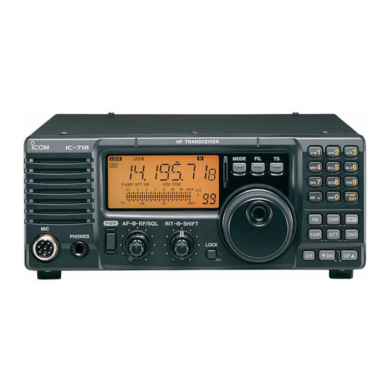
Icom IC-718 User manual

INSTRUCTION MANUAL
HF ALL BAND TRANSCEIVER
i718

i
IMPORTANT
READ ALL INSTRUCTIONS carefully and com-
pletely before using the transceiver.
SAVE THIS INSTRUCTION MANUAL— This
instruction manual contains basic operating instruc-
tions for the IC-718.
EXPLICIT DEFINITIONS
WORD DEFINITION
RDANGER! Personal death, serious injury or an ex-
plosion may occur.
RWARNING! Personal injury, fire hazard or electric
shock may occur.
CAUTION Equipment damage may occur.
NOTE Recommended for optimum use. No risk
of personal injury, fire or electric shock.
PRECAUTIONS
RDANGER HIGH VOLTAGE! NEVER touch
an antenna connector during transmission.
This may result in an electrical shock or burn.
RWARNING RF EXPOSURE! This radio
emits Radio Frequency (RF) energy. Extreme caution
should be observed when operating this radio. If you
have any questions regarding RF exposure and safety
standards please refer to the Federal Communications
Commission Office of Engineering and Technology’s
report on Evaluating Compliance with FCC Guidelines
for Human Radio Frequency Electromagnetic Fields
(OET Bulletin 65).
RWARNING! NEVER operate the radio while
driving a vehicle. Safe driving requires your full atten-
tion—anything less may result in an accident.
RWARNING! NEVER operate the radio with an
earphone or other audio accessories at high volume
levels.
Continuous high volume operation may cause a ring-
ing in your ears. If you experience ringing, reduce the
volume level or discontinue use.
RWARNING! NEVER connect the radio to an
AC outlet. This may pose a fire hazard or result in an
electric shock.
RWARNING! NEVER connect the radio to a
power source of more than 16 V DC such as a 24 V
DC. This could cause a fire or damage the radio.
RWARNING! NEVER reverse the DC power
cable polarity when connecting to a power source.
This could damage the radio.
RWARNING! NEVER cut the DC power cable
between the DC plug and fuse holder. If an incorrect
connection is made after cutting, the radio may be
damaged.
RWARNING! NEVER let metal, wire or other ob-
jects touch any internal part or connectors on the rear
panel of the radio.
This may result in an electric shock or this could cause
a fire or damage the radio.
RWARNING! NEVER operate or touch the radio
with wet hands. This may result in an electric shock or
may damage the radio.
RWARNING! Immediately turn the radio power
OFF and remove the power cable if it emits an abnor-
mal odor, sound or smoke. Contact your Icom dealer
or distributor for advice.
CAUTION: NEVER expose the radio to rain, snow
or any liquids.
CAUTION: NEVER change the internal settings of
the radio. This may reduce radio performance and/or
damage to the radio.
CAUTION: NEVER place the radio where normal
operation of the vehicle may be hindered or where it
could cause bodily injury.
DO NOT operate the radio near unshielded electrical
blasting caps or in an explosive atmosphere.
DO NOT push the PTT when not actually desiring to
transmit.
DO NOT use harsh solvents such as benzine or al-
cohol to clean the radio, as they will damage the ra-
dio’s surfaces. If the radio becomes dusty or dirty,
wipe it clean with a soft, dry cloth.

ii
DO NOT operate or place the radio in areas with
temperatures below –10°C (+14°F) or above +60°C
(+140°F).
Be aware that temperatures on a vehicle’s dashboard
can exceed +80°C (+176°F) in direct sunlight, result-
ing in permanent damage to the radio if left there for
extended periods.
DO NOT place the radio in excessively dusty envi-
ronments or in direct sunlight.
DO NOT place the radio against walls or put any-
thing on top of the radio. This will obstruct heat dissi-
pation.
Place the radio in a secure place to avoid inadvertent
use by children.
During mobile operation, NEVER place the radio
where air bag deployment may be obstructed.
During mobile operation, DO NOT place the radio
where hot or cold air blows directly onto it.
During mobile operation, DO NOT operate the radio
without running the vehicle’s engine. When radio
power is ON and your vehicle’s engine is OFF, the ve-
hicle’s battery will soon become exhausted.
Make sure the radio power is OFF before starting the
vehicle engine. This will avoid possible damage to the
radio by ignition voltage spikes.
During maritime mobile operation, keep the radio and
microphone as far away as possible from the magnetic
navigation compass to prevent erroneous indications.
BE CAREFUL! The heatsink will become hot when
operating the radio continuously for long periods of
time.
BE CAREFUL! If a linear amplifier is connected,
set the radio’s RF output power to less than the linear
amplifier’s maximum input level, otherwise, the linear
amplifier will be damaged.
Use only supplied or optional Icom microphones.
Other manufacturer’s microphones have different
pin assignments, and connecting to the IC-718 may
damage the radio.
PRECAUTIONS (Continued)
• FOR CLASS B UNINTENTIONAL RADIATORS
This equipment has been tested and found to comply
with the limits for a Class B digital device, pursuant to
part 15 of the FCC Rules. These limits are designed to
provide reasonable protection against harmful interfer-
ence in a residential installation. This equipment gen-
erates, uses and can radiate radio frequency energy
and, if not installed and used in accordance with the
instructions, may cause harmful interference to radio
communications. However, there is no guarantee that
interference will not occur in a particular installation.
If this equipment does cause harmful interference to
radio or television reception, which can be determined
by turning the equipment off and on, the user is en-
couraged to try to correct the interference by one or
more of the following measures:
• Reorient or relocate the receiving antenna.
• Increase the separation between the equipment and
receiver.
• Connect the equipment into an outlet on a circuit dif-
ferent from that to which the receiver is connected.
• Consult the dealer or an experienced radio/TV tech-
nician for help.
This device complies with Part 15 of the FCC Rules.
Operation is subject to the following two conditions: (1)
this device may not cause harmful interference, and
(2) this device must accept any interference received,
including interference that may cause undesired op-
eration.
WARNING: MODIFICATION OF THIS DEVICE TO
RECEIVE CELLULAR RADIOTELEPHONE SERVICE
SIGNALS IS PROHIBITED UNDER FCC RULES AND
FEDERAL LAW.
CAUTION: Changes or modifications to this device,
not expressly approved by Icom Inc., could void your
authority to operate this device under FCC regula-
tions.
FCC INFORMATION
DISPOSAL
The crossed-out wheeled-bin symbol
on your product, literature, or packaging
reminds you that in the European Union,
all electrical and electronic products, bat-
teries, and accumulators (rechargeable
batteries) must be taken to designated
collection locations at the end of their
working life. Do not dispose of these prod-
ucts as unsorted municipal waste.
Dispose of them according to the laws in
your area.

iii
q
w
er
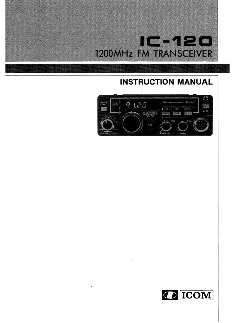
The transceiver comes with the following accessories.
Qty.
q DC power cable ................................................... 1
w Hand microphone (HM-36) ................................. 1
e Fuse (FGB 4 A; internal fuse) ............................. 1
r Fuse (ATQ 25 A; for DC cable) ........................... 2
SUPPLIED ACCESSORIES

1
1
TABLE OF CONTENTS
IMPORTANT ............................................................ i
EXPLICIT DEFINITIONS .......................................... i
PRECAUTIONS ..................................................... i–ii
FCC INFORMATION ................................................ ii
SUPPLIED ACCESSORIES .................................... iii
1 TABLE OF CONTENTS ...................................... 1
2 PANEL DESCRIPTION ................................... 2–8
Front panel ....................................................... 2
Function display ............................................... 5
Rear panel ........................................................ 6
Microphone (HM-36) ........................................ 8
3 INSTALLATION AND CONNECTIONS ........ 9–14
Unpacking ........................................................ 9
Selecting a location .......................................... 9
Grounding ........................................................ 9
Connecting an antenna .................................... 9
Required connections .................................... 10
Advanced connections ................................... 11
Connecting the Power supply ........................ 12
Connecting a liner amplifier ............................ 13
External antenna tuners ................................. 14
4 FREQUENCY SETTINGS ........................... 15–19
Resetting the CPU ......................................... 15
Initial settings ................................................. 15
VFO description ............................................. 16
Frequency setting ........................................... 17
Dial lock function ............................................ 19
5 RECEIVE AND TRANSMIT ......................... 20–34
Mode selection ............................................... 20
RF gain and Squelch ...................................... 20
Function for receive ........................................ 21
DSP function
(Requires an optional UT-106 DSP UNIT) ........ 23
Filter selection ................................................ 24
Filter setting .................................................... 25
Split frequency operation ............................... 26
SWR ............................................................... 26
Function for transmit ...................................... 27
Function for CW ............................................. 31
Function for RTTY .......................................... 33
6 MEMORY OPERATION .............................. 35–38
Memory channels ........................................... 35
Memory channel selection .............................. 35
Memory channel entry .................................... 36
Transferring data to the VFO .......................... 37
Memory clearing ............................................. 38
7 SCANS ........................................................ 39–40
Scan types ..................................................... 39
Preparation ..................................................... 39
Programmed scan operation .......................... 40
Memory scan operation .................................. 40
8 SET MODE .................................................. 41–47
General .......................................................... 41
Quick Set mode items ............................... 42-43
Initial Set mode items ................................ 44-47
9 INSTALLATION AND CONNECTIONS ...... 48–51
Opening the transceiver’s case ...................... 48
Installing the MB-118
MOBILE MOUNTING BRACKET ......................... 48
CR-338 HIGH STABILITY CRYSTAL UNIT ........ 49
UT-106 DSP RECEIVE UNIT ............................ 50
Optional IF filters ............................................ 50
AT-180 internal switch .................................... 51
10 MAINTENANCE ........................................ 52–53
Troubleshooting ............................................. 52
Fuse replacement .......................................... 53
Resetting the CPU ......................................... 53
11 SPECIFICATIONS .......................................... 54
12 OPTIONS .................................................. 55–56
13 CONTROL COMMAND ............................ 57–58
Remote jack (CI-V) information ...................... 57
14 INSTALLATION NOTES ................................. 59
INDEX .............................................................. 60–62

qPOWER SWITCH [PWR]
➥Push momentarily to turn ON the power.
• First, confirm the optional DC power supply is ON.
➥Hold down for 1 second to turn OFF the power.
➥While holding down [SET], push [PWR] to enter
the Initial Set mode. (p. 41)
wMICROPHONE CONNECTOR [MIC]
Connect supplied or optional microphone.
• See p. 55 for appropriate microphones.
• See p. 8 for microphone connector information.
eHEADPHONE JACK [PHONES] (p. 11)
Connect headphones (8 ).
• When headphones are connected, the internal speaker
or external speaker does not function.
rAF CONTROL [AF] (inner control)
Rotate to adjust the audio output level.
tRF GAIN/SQUELCH CONTROL [RF/SQL]
(outer control: pp. 20, 44)
Rotate to adjust the squelch threshold level. The
squelch removes noise output from the speaker
(closed condition) when no signal is received.
• The squelch is usable for all modes.
• The control can be set as the squelch plus RF gain con-
trols or squelch control only (RF gain is fixed at maxi-
mum) in initial set mode.
yRIT CONTROLS [RIT] (Inner control: p. 21)
➥Rotate to shift the receive frequency without
changing the transmit frequency.
•
Rotate clockwise to increase the frequency, or rotate
counterclockwise to decrease the frequency. “
RIT
RIT
”
appears on the display.
• The shift frequency range is ±1.2 kHz.
uIF SHIFT CONTROLS [SHIFT]
(Outer control: p. 21)
Rotate to shift the center frequency of the receiver’s
IF passband.
•
Rotate clockwise to shift the center frequency higher, or
counterclockwise to shift the center frequency lower.
iLOCK SWITCH [LOCK]
➥Push momentarily to turn the Dial Lock function
ON or OFF. (p. 19)
• The Dial Lock function electronically locks the main
dial.
oMAIN DIAL
Rotate to change the displayed frequency, selects
Quick/Initial set mode items, and so on.
!0 PREAMP SWITCH [P.AMP] (p. 21)
Push momentarily to turn the preamp ON or OFF.
!1 CH SWITCH [CH] (p. 35)
Push momentarily to turn the Memory Channel Se-
lect function ON or OFF.
• [MEMO] blinks while the Memory Channel Select func-
tion is turned ON.
• Push one or more times (or hold down)[√DN]/[UP ∫]
until a desired Memory channel appears.
• After pushing [F-INP/ENT], push a desired Memory
channel number from the keypad, then push [F-INP/
ENT] again to directly select the Memory Channel.
• Push [CH] to exit the Memory Channel Select function.
2
2
PANEL DESCRIPTION
MIC
IC-718
PHONES
RF/SQLAF SHIFTRIT
LOCK
MODE
FIL
TS
PWR
TUNER
COMP
P. A M P
NB
ATT
SET
CH
ENT
F-INP
V/M
1
MW
4
A=B
2
M-CL
5
SCN
8
ANF
0
NR
.
A/B
3
VOX
97
SPL
M V
6
ZDN UP Y
Speaker Function Display @1 @0 !9 !7
!5
!4
!6
!3
!2
!0
!8
!1
oi
uy
tre
w
q
Front panel

3
2
PANEL DESCRIPTION
!2 MEMORY CHANNEL (BAND) UP/DOWN
SWITCHES [√DN]/[UP ∫](p. 35)
➥Push one or more times to select a Memory
channel, while “MEMO” is blinking.
➥Push to select a band.
➥Push to select an item in the Quick/Initial Set
mode.
!3 ATTENUATOR SWITCH [ATT] (p. 22)
Push to turn the 20 dB Attenuator function ON or
OFF.
!4 TUNER SWITCH [TUNER] (pp. 29, 30)
➥Push to turn the Automatic Antenna Tuner func-
tion ON or OFF.
• An optional antenna tuner must be connected.
➥Hold down for 1 second to manually start the
tuner.
• An optional antenna tuner must be connected.
• When the tuner cannot tune the antenna within 20 sec-
onds, the tuning circuit is automatically bypassed.
!5 SET SWITCH [SET]
➥Hold down for 1 second to enter the Quick Set
mode. (p. 41)
➥While holding down [SET], push [POWER] to
enter the Initial Set mode. (p. 41)
➥Push to select the Meter function. (p. 28)
• PO: Displays the relative RF output power.
• ALC: Displays ALC level.
• SWR: Displays the SWR over the transmission line.
!6 MIC COMPRESSOR SWITCH [COMP] (p. 28)
Toggles the Microphone Compressor function ON or
OFF.
!7 KEYPAD (pp. 4, 35)
The keypad can be used for direct frequency input,
Memory channel selection, or secondary functions.
!8 NOISE BLANKER SWITCH [NB] (p. 22)
➥Push to turn the Noise Blanker ON or OFF. The
Noise Blanker reduces pulse-type noise such as
that generated by automobile ignition systems.
This function is not effective against non pulse-
type noise.
➥Hold down [NB] for 1 second to enter the Noise
Blanker Level Setting mode.
!9 QUICK TUNING STEP SWITCH [TS] (pp. 18, 19)
➥Selects a Quick Tuning step or turns OFF the
Quick Tuning step.
• While the Quick Tuning icon (“”) is displayed, the
frequency is changed in kHz step.
➥While the Quick Tuning step is OFF, hold down
for 1 second to turn the 1 Hz step ON or OFF.
• A 1 Hz indication appears and the frequency is
changed in 1 Hz steps.
➥
While the kHz Quick Tuning step is selected, hold
down for 1 second to enter the Tuning Step Set
mode.
@0 FILTER SWITCH [FIL] (p. 24)
Push to select the preset normal, wide, or narrow IF
filters for the selected operating mode.
@1 MODE SWITCHES [LSB/USB]/[CW/CW-R]/
[RTTY/RTTY-R]/[AM] (p. 20)
Push to select an operating mode.
• In the SSB mode, holding down [MODE] for 1 second
toggles between LSB and USB.
• In the CW mode, holding down [MODE] for 2 seconds
toggles between CW and CW Reverse.
• In the RTTY mode, holding down [MODE] for 2 seconds
toggles between RTTY and RTTY Reverse.
• “ ” appears when the Reverse mode is selected.

4
2PANEL DESCRIPTION
@2 VFO/MEMORY SWITCH/1 [V/M•1] (pp. 16, 35)
Push to toggle the operating mode between VFO
and Memory.
@3 MEMORY WRITE SWITCH/4 [MW•4] (p. 36)
Hold down for 1 second to enter the displayed fre-
quency and operating mode into the selected Mem-
ory channel.
@4 SPLIT SWITCH/7 [SPL•7] (p. 26)
Push to turn the Split Frequency function ON or
OFF.
@5 NR SWITCH/. [NR• . ] (p. 23)
➥Push to turn the Noise Reduction function ON or
OFF. This function can be used in all modes.
• An optional UT-106 DSP UNIT is required.
• “NR” appears on the display.
➥Hold down for 1 second to enter the Noise Re-
duction Level Set mode.
@6 ANF SWITCH/0 [ANF•0] (p. 23)
Push to turn the Automatic Notch Filter function ON
or OFF.
This function can be used in SSB and AM modes.
• An optional UT-106 DSP UNIT is required.
• “ANF” appears on the display.
@7 FREQUENCY INPUT/ENTER SWITCH
[F-INP/ENT]
➥Push [F-INP/ENT] to enter the Direct Frequency
Input mode.
➥After pushing [CH], push [F-INP/ENT] to enter
the Direct Memory Number Selection mode.
@8 SCAN SWITCH/8 [SCAN•8] (p. 39)
➥Push to start or stop the Programmed Scan in
the VFO mode.
➥Push to start or stop the Memory Scan in the
Memory mode.
@9 VOX SWITCH/9 [VOX•9] (p. 28)
In the SSB modes, push to turn the VOX function
ON or OFF.
#0 M≈V SWITCH/6 [MV•6] (p. 37)
Hold down for 1 second to copy the memory con-
tents to the VFO.
#1 MEMORY CLEAR SWITCH/5 [M=CL•5] (p. 38)
In the Memory mode, hold down for 1 second to
clear the selected Memory channel contents.
• “BLANK” appears above the Memory channel number.
#2 VFO SELECT SWITCH/3 [A/B•3] (p. 16)
➥In the VFO mode, push to toggle between VFO
A and VFO B.
➥When the Split Frequency function is ON, push
to toggle between the transmit and the receive
frequency.
#3 VFO EQUALIZATION SWITCH/2 [A=B•2]
Push to equalize the VFO B frequency and oper-
ating mode to the VFO A frequency and operating
mode.
ENT
F-INP
V/M
1
MW
4
A=B
2
M=CL
5
SCN
8
ANF
0
NR
.
A/B
3
VOX
97
SPL
M V
6
#1
@8
K
MODE
FILTER
TS
TUNER
COMP
P.AMP
UP
NB
ATT
SET
CH
DN
ENT
F-INP
V/M
1
MW
4
A=B
2
M=CL
5
SCN
8
ANF
0
NR
.
A/B
3
VOX
97
SPL
M V
6
ZY
@5
@4
@3
@2
@7
@9
#0
@6
#3 #2
Front panel (continued)

qLOCK ICON (p. 19)
Displayed when the Dial Lock function is in use.
wRECEIVE ICON
Displayed while receiving a signal or when the
squelch is open.
eTUNE ICON
Displayed while the Automatic Tuning function is in
use.
rTRANSMIT ICON
Displayed while transmitting.
tFUNCTION ICONS
➥“P.AMP” is displayed when antenna preamp is in
use.
➥“ATT” is displayed when the Attenuator function
is in use.
➥“NB” is displayed when the Noise Blanker func-
tion is ON.
➥“BK” is displayed when the Semi Break-in func-
tion is selected in Quick Set mode.
➥“F-BK” is displayed when the Full Break-in func-
tion is selected in the CW mode. (p. 31)
➥“VOX” is displayed when the VOX function is se-
lected in the Quick Set mode.
➥“COM” is displayed when the speech compres-
sor is ON in the SSB mode.
➥“SCAN” is displayed when the Scan function is in
use.
• Blinks when a scan is paused.
yDSP UNIT ICON
Displayed when an optional UT-106 DSP UNIT is in-
stalled.
u
AUTOMATIC NOTCH FILTER
ICON
(p. 23)
Displayed when the optional Automatic Notch Filter
function is in use.
iNOISE REDUCTION ICON (p. 23)
Displayed when the optional Noise Reduction func-
tion is in use.
oSIGNAL/SQL/RF-GAIN METER
➥Displays the signal strength while receiving.
➥Displays the relative output power, ALC, or SWR
levels while transmitting. (p. 27)
!0 VFO/MEMORY ICON (p. 16)
“VFO A” or “VFO B” is displayed when the VFO
mode is selected.
“MEMO” is displayed when the Memory mode is se-
lected.
!1 MEMORY CHANNEL NUMBER READOUT (p. 35)
Displays the selected Memory channel number.
!2 BLANK ICON (p. 38)
Indicates that the selected Memory channel has no
content.
• This icon appears both in VFO and Memory mode.
!3 SPLIT ICON (p. 26)
Displayed when the Split function is ON.
!4 RIT ICON (p. 21)
Displayed when the RIT function is in use.
!5 FREQUENCY READOUT
Displays the operating frequency.
!6 REVERSE ICON (p. 20)
Displayed when the CW reverse or RTTY reverse
mode is selected.
!7
WIDE/NARROW FILTER
ICON
S(pp. 24, 25)
➥
“” is displayed when the wide IF filter is se-
lected.
➥“” is displayed when the narrow IF filter is se-
lected.
!8 PROGRAMMABLE TUNING STEP ICON
Displayed when you select the programmable tun-
ing step.
!9 MODE ICONS (p. 20)
Displays the selected operating mode.
5
2
PANEL DESCRIPTION
!9 !6
!7
!8
o!1!0
r
e
w
!4
!2
!5
!3
t
q
y
u
i
Function display

6
2PANEL DESCRIPTION
qANTENNA CONNECTOR [ANT] (p. 10)
Connects to a 50 antenna with a PL-259 plug
connector and a 50 coaxial cable.
wDC POWER SOCKET [DC 13.8V] (p. 12)
Connects to a 13.8 V DC source through the sup-
plied DC power cable.
eTUNER CONTROL SOCKET [TUNER] (p. 14)
Connects to the control cable from an optional AH-4
AUTOMATIC ANTENNA TUNER.
rCI-V REMOTE CONTROL JACK [REMOTE] (p. 57)
Connects to a PC for remote control of the of trans-
ceiver functions.
tEXTERNAL SPEAKER JACK [EXT SP] (p. 11)
Connects to an 8 external speaker.
• When an external speaker is connected, the internal
speaker is disabled.
yACCESSORY SOCKET [ACC] (p. 7)
Connects to external equipment such as a linear
amplifier, an automatic antenna tuner, a TNC for
data communications, and so on.
uELECTRONIC KEYER JACK [KEY]
Accepts a key or paddle connector for the internal
electronic keyer.
• You can setlect the keyer type between the internal
electronic keyer and straight key operation in the Initial
Set mode.
When connecting
a straight key
When connecting
a paddle
(dot)
(com)
(dash)
(⊕)
iALC INPUT JACK [ALC]
Connects to the ALC output jack of a non-Icom lin-
ear amplifier.
oSEND CONTROL JACK [SEND] (p. 14)
Goes to ground while transmitting to control exter-
nal equipment such as a liner amplifier.
• Maximum control level: 16 V DC/2 A
!0 GROUND TERMINAL [GND] (p. 9)
Connects to ground to prevent electrical shock, TVI,
BCI and other problems.
qe
rtyuio!
0
w
Rear panel
Rear panel view

7
2
PANEL DESCRIPTION
DACC SOCKET INFORMATION
• ACC socket
ACC PIN # NAME DESCRIPTION SPECIFICATIONS
1 8 V Regulated 8 V output. Output voltage: 8 V ±0.3 V
Output current: Less than 10 mA
2 GND Connects to ground. —
3 SEND
Input/output pin.
Goes to ground when transmitting.
When grounded, transmits.
Ground level: –0.5 V to 0.8 V
Input current: Less than 20 mA
4 BDT Data line for the optional AT-180. —
5 BAND Band voltage output.
(Varies with amateur band) Output voltage: 0 to 8.0 V
6 ALC ALC voltage input. Control voltage: –4 to 0 V
Input impedance: More than 10 k
7NC — —
8 13.8 V 13.8 V output when power is ON. Output current: Maximum 1 A
9 TKEY Key line for the AT-180. —
10 FSKK RTTY keying input. Ground level: –0.5 to 0.8 V
Input current: Less than 10 mA
11 MOD Modulator input. Input impedance: 10 k
Input level: Approx. 100 mV rms
12 AF AF detector output.
Fixed, regardless of [AF] position.
Output impedance: 4.7 k
Output level: 100 to 300 mV rms
13 SQL S Squelch output.
Goes to ground when squelch opens.
SQL open: Less than 0.3 V/5 mA
SQL closed: More than 6.0 V/100 µA
• When connecting the ACC conversion cable (OPC-599)
ACC 1
ACC 2
qFSKK tAF
wGND ySQLS
eSEND u13.8 V
rMOD iALC
q8 V tALC
wGND yNC
eSEND u13.8 V
rBAND
1
1
2
2
3
3
4
4
8
8
7
7
6
6
5
5
9
10 11 12
13
1
2
3
4
76
5
When the SEND terminal controls an inductive load (such as a relay), a counter-electromotive force can cause the transceiver
to malfunction or other damage.To prevent this, we recommend adding a switching diode, such as an “1SS133,” on the load side
of the circuit to the counter-electromotive force absorption. When the diode is added, a switching delay of the relay may occur.
Be sure to check its switching action before operation.
eSEND
i13.8V
ACC
socket
Relay
Switching diode To a non-Icom
linear amplifier
[Example]
Rear panel
view
1234
8765
9
10 11 12
13

8
2PANEL DESCRIPTION
qUP/DOWN SWITCHES [UP]/[DN]
Change the selected readout frequency or Memory
channel.
• Holding down continuously changes the frequency or
Memory channel number.
• The [UP]/[DN] switch can simulate a key paddle. Preset
in CW PADDL in the Initial Set mode. (p. 31)
wPTT SWITCH
Push to transmit, release to receive.
• MICROPHONE CONNECTOR
(Front view)
yGND (PTT ground)
tPTT
rMain readout squelch switch
qMicrophone input
w+8 V DC output
eFrequency up/down
uGND
(Microphone ground)
iMain readout AF output
(varies with [AF]/[BAL])
[MIC]
PIN NO. FUNCTION DESCRIPTION
w+8 V DC output Maximum 10 mA
eFrequency up Ground
Frequency down Ground through 470
rSquelch open “LOW” level
Squelch close “HIGH” level
CAUTION: DO NOT short pin 2 to ground as this
can damage the internal 8 V regulator. DC voltage is
also applied to pin 1 for microphone operation. Use
caution when using a non-Icom microphone.
• HM-36 SCHEMATIC DIAGRAM
+
q
w
ert
y
u
i
4700 pF
0.33 µF
Microphone
MIC
ELEMENT
22 kø
470 ø
DOWN UP
PTT
RECEIVE
TRANSMIT
Microphone Cable
Microphone Plug
1 kø
+
10 µF
q
w
Microphone (HM-36)

3
9
INSTALLATION AND CONNECTIONS
Unpacking
After unpacking, immediately report any damage to the
delivering carrier or dealer. Keep the shipping cartons.
For a description and a diagram of accessory equip-
ment included with the IC-718, see ‘Supplied accesso-
ries’ on page 1 of this manual.
Selecting a location
Select a location for the transceiver that allows ade-
quate air circulation, free from extreme heat, cold, or
vibrations, and away from TV sets, TV antenna ele-
ments, radios and other electromagnetic sources.
The base of the transceiver has an adjustable stand
for desktop use. Set the stand to one of two angles to
suit your operating conditions.
Grounding
To prevent electrical shock, television interference
(TVI), broadcast interference (BCI) and other prob-
lems, ground the transceiver through the GROUND
terminal on the rear panel.
For best results, connect a heavy gauge wire or strap
to a long earth-sunk copper rod. Make the distance
between the [GND] terminal and ground as short as
possible.
RWARNING! NEVER connect the [GND]
terminal to a gas or electric pipe, since the connec-
tion could cause an explosion or electric shock.
Connecting an antenna
For radio communications, the antenna is of critical im-
portance, along with output power and receiver sensi-
tivity. Select antenna(s), such as a well-matched 50
antenna, and feedline. A Voltage Standing Wave Ratio
(VSWR) of 1.5:1 or less is recommended for your desired
band.
NOTE: A lightening arrestor may offer some pro-
tection from static electricity.
Antenna SWR
Each antenna is tuned for a specified frequency range
and SWR may increase out of that range. When the
SWR is higher than approximately 2.0:1, the trans-
ceiver’s power drops to protect the final transistor.
In this case, an antenna tuner is useful to match the
transceiver and antenna. The IC-718 has an SWR
meter to continuously monitor the antenna SWR
.

10
3INSTALLATION AND CONNECTIONS
Required connections
MIC
i718
PHONES
RF/SQLAF SHIFTRIT
LOCK
MODE
FIL
TS
PWR
TUNER
Y
Z
COMP
P.AMP
UP
NB
ATT
SET
CH
DN
ENT
F-INP
V/M
1
MW
4
A=B
2
M-CL
5
SCN
8
ANF
0
NR
.
A/B
3
VOX
97
SPL
M V
6
MICROPHONES (p. 55)
SM-30HM-36 SM-50
• Front panel (Microphone)
• Rear panel (Basic connection)
GROUND (p. 9)
Use the heaviest gauge wire
or strap available and make
the connection as short as
possible.
Grounding prevents electrical
shocks, TVI and other prob-
lems.
ANTENNA (p. 56)
[Example]: 1.8 to 30 MHz bands
DC POWER SUPPLY
PS-126
CW KEY
A straight or bug key can be used
when the internal electronic keyer is
turned OFF in “CW PADDL” in the Ini-
tial Set mode. (p. 31)
approx. 24.5 m; 80.3 ft
AH-710

11
3
INSTALLATION AND CONNECTIONS
Advanced connections
MIC
IC-718
PHONES
RF/SQLAF SHIFTRIT
LOCK
MODE
FIL
TS
PWR
TUNER
Y
Z
COMP
P.AMP
UP
NB
ATT
SET
CH
DN
ENT
F-INP
V/M
1
MW
4
A=B
2
M-CL
5
SCN
8
ANF
0
NR
.
A/B
3
VOX
97
SPL
M V
6
MIC
The AFSK modulation signal can be
input from [MIC]. (p. 33)
HEADPHONES
• Front panel (Microphone and headphones)
ANTENNA (p. 13)
Connects a liner amprifier,
and so on.
[SEND], [ALC]
(p. 14)
Used to connect to a
non-Icom linear ampli-
fier.
EXTERNAL SPEAKER (p. 55)
SP-23
(Option)
ACC SOCKET (p. 7)
AH-4 or AH-740 (p. 55)
AH-2b
or a long wire
with
[REMOTE] (p. 57)
Used for remote control and transceive operation.
The optional CT-17 is required when connecting a
PC to [REMOTE].
• Rear panel (Optional products and external equipment)

12
3INSTALLATION AND CONNECTIONS
Connecting the Power supply
Use an optional PS-126 DC POWER SUPPLY when op-
erating the IC-718 with AC power. Refer to the dia-
grams below.
CAUTION: Before connecting the DC power cable,
check the following important items. Make sure:
• The [POWER] switch is OFF.
• Output voltage of the power source is 12 to 15 V
when you use a non-Icom power supply.
• DC power cable polarity is correct.
Red: Positive +terminal
Black: Negative _terminal
CONNECTING A VEHICLE BATTERY
CONNECTING A NON-ICOM DC POWER SUPPLY
1234
8765
9
10 11 12
13
DC power
socket
DC power supply AC outlet
AC cable
25 A fuses
Supplied
DC power cable
13.8 V 25 A
_+
black
red
+
_
CONNECTING THE PS-126 DC POWER SUPPLY
1234
8765
9
10 11 12
13
PS-126
Connect to an AC outlet
using the supplied AC cable.
DC power cable
DC power
socket
• RWARNING! NEVER connect to a battery with-
out using a DC fuse, otherwise a fire hazard
could occur or damage to the transceiver.
• NEVER connect the transceiver to a 24 V battery.
The transceiver may not receive well on some fre-
quencies when installed in a hybrid vehicle, or any
type of electric vehicle (fuel cell vehicle). This is be-
cause vehicle’s electric components, such as the
inverter system, generate a lot of electric noise.
• DO NOT use a cigarette lighter socket as a pow-
er source when operating in a vehicle. The plug
may cause voltage drops and ignition noise may
be superimposed onto transmit or receive audio.
• Use a rubber grommet when passing the DC
power cable through a metal plate to prevent a
short circuit.
12 V
battery
Supplied
DC power cable
+red
_black Crimp
Solder
Grommet
NOTE: Use terminals for
the cable connections.

13
3
INSTALLATION AND CONNECTIONS
Connecting a linear amplifier
CONNECTING THE IC-PW1/EURO
1234
8765
9
10 11 12
13
ANT
ACC-1
ACC REMOTE
REMOTE
INPUT1
GND
GND
IC-PW1/EURO
IC-718
Ground
To an AC outlet
Non-European versions: 100 V to 120 V/220 V to 240 V
European version: 230 V
Coaxial cable
(supplied with the IC-PW1/EURO)
ACC cable (supplied with the IC-PW1/EURO)
Remote control cable (supplied with the IC-PW1/EURO)
To an
antenna
EXCITER
1 1&2
OPC-599 conversion cable
(option)
CONNECTING A NON-ICOM LINER AMPLIFIER
1234
8765
9
10 11 12
13
RF OUTPUT RF INPUT
ALC
SEND
50 Ωcoaxial cable
IC-718
ANT
ALC
SEND
To an
antenna
Non-Icom linear amplifier
RWARNING!
Set the transceiver output
power and linear amplifier
ALC output level referring to
the linear amplifier instruc-
tion manual.
The ALC input level must
be in the range 0 V to –4 V.
The transceiver does not ac-
cept a positive voltage. Non-
matched ALC and RF power
settings could cause a fire or
ruin the linear amplifier. The specifications for the SEND relay are 16 V
DC 2 A. If this level is exceeded, a large external
relay must be used.

CONNECTING THE AT-180 (p. 29)
DO NOT connect an AT-180 and AH-4 or AH-740
at the same time. Both tuners will not function cor-
rectly.
When connecting the AT-180, turn OFF the IC-
718’s power, otherwise, the CPU may malfunction
and the AT-180 may not function properly.
14
3INSTALLATION AND CONNECTIONS
External antenna tuners
CONNECTING THE AH-4 (p. 30)
Coaxial cable (from the AH-4)
Long wire or optional AH-2b
Ground
IC-718 AH-4
Control cable
Ground
1234
8765
9
10 11 12
13
Ground
HF
antenna
[ANT] [ACC] [ACC]AT-180
ACC cable supplied with the AT-180
Coaxial cable supplied
with the AT-180
IC-718
one of two
connectors
CONNECTING THE AH-740 (p. 30)
OPC-2321
Coaxial cable (from the AH-740)
Ground
Ground
IC-718
AH-740
Coaxial cable and control cable connections
Rubber
vulcanizing
tape, then
electrical
tape.
Coaxial
cable
OPC-2321
Ground
strap
Vehicle chassis or body
About the ground strap connection
• The coaxial cable is supplied with the AH-740.
The OPC-2321 Control cable is optional.
• See the AH-740 instruction manual for the installation and con-
nection details.

4
15
FREQUENCY SETTINGS
Initial settings
After resetting the transceiver, set the controls and
switches as shown in the figure below.
[PWR] [ZDN][UP Y]
[METER]: Po
[LOCK]: OFF
[POWER]: OFF [P.AMP], [ATT]: OFF
[RIT]: Center
[IF SHIFT]: Center
[AF]: Max. counter clockwise
[RF/SQL]: 12 o’clock
[NB], [COMP]: OFF
Turn ON the power, then check the display. If any of
the following icons appear, turn them OFF as follows.
• Quick tuning step icon (“√”):Push [TS].
• 1 Hz frequency readout:
Hold down [TS] for 1
second.
(When Quick Tuning step
is OFF.)
• RIT icon (“
RIT
RIT
”): Set the [RIT] control to
the center position.
• Split icon (“ ”): Push [SPL].
In cooler temperatures, the LCD may appear dark
and unstable after turning ON the power. This is
normal and does not indicate any equipment mal-
function.
Resetting the CPU
Before first applying power, make sure all connections
required for your system are complete by referring to
Chapter 3. Then, reset the transceiver using the fol-
lowing procedure.
A resetting CLEARS all Memory channel program-
ming and returns all Quick Set mode and Initial Set
mode settings to their factory defaults.
qMake sure the transceiver power is OFF.
wWhile holding down [UP ∫] and [√ DN], hold down
[PWR] for 1 second to turn ON the power.
• The internal CPU is reset.
• The transceiver displays its initial VFO frequencies
when resetting is complete.
eAll Quick Set mode and Initial Set mode settings
are returned to their default values. (p. 41)

16
4FREQUENCY SETTINGS
VFO description
VFO is an abbreviation of Variable Frequency Oscilla-
tor, and traditionally refers to an oscillator.
The IC-718 VFOs can store frequencies and operat-
ing modes
You can set a desired frequency in the VFO with the
[MAIN DIAL], the keypad or the Memory Copy function.
(p. 37) You can also select the operating mode with the
[MODE] switch or call up previously accessed frequen-
cies and modes with the Band Stacking Register. (p.
18)
The IC-718 has two VFOs, VFO A and VFO B, es-
pecially suited for split frequency operation. You can
easily use an operating frequency.
• Differences between the VFO mode and the Memory mode
VFO MODE
Each VFO displays a frequency and operating mode.
If the frequency or mode is changed, the VFO auto-
matically memorizes the new frequency or mode.
When you select a VFO, the last used frequency and
mode appear, even if another frequency or mode is
selected in another VFO or Memory channel.
[EXAMPLE]
MEMORY MODE (pp. 35–38)
Each Memory channel shows a frequency and oper-
ating mode like a VFO. Even if the frequency or mode
is changed, the Memory channel does not memorize
the new frequency or mode.
When you select the Memory channel, the memorized
frequency and mode appear, even if the frequency or
mode is changed in the memory, then another mem-
ory or VFO is selected.
[EXAMPLE]
VFO is selected.
The frequency
is changed.
Memory mode
is selected.
VFO is selected
again.
Memory channel 1
is selected.
The frequency
is changed.
Another Memory
channel is selected.
Memory channel 1
is selected again.
Memorized frequency (14.100 MHz) appears instead of
the changed frequency (14.123 MHz).
Last used frequency (14.123 MHz) appears.
Other manuals for IC-718
10
Table of contents
Other Icom Transceiver manuals

Icom
Icom IC-40G User manual

Icom
Icom IC-2300H User manual

Icom
Icom IC-M34 User manual

Icom
Icom IC-V80 User manual

Icom
Icom IC-W21AT User manual

Icom
Icom IC-F3021T/S User manual

Icom
Icom IC-X2A User manual

Icom
Icom IC-U82 Installation and operating instructions

Icom
Icom ic-f5021 User manual

Icom
Icom IC-3220A User manual