5
REMOTE CONTROL
Remote control (CI-V) information
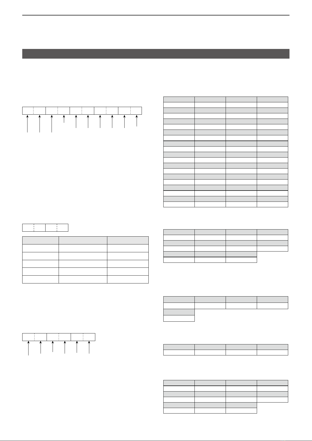
DCommand table
Command Sub Data Description
16* 42 00/01 Send/read the Repeater tone
(00=OFF, 01=ON)
43 00 ~ 02 Send/read the Tone squelch
(00=OFF, 01=TSQL, 02=TSQL-R)
46 00/01 Send/read the VOX function
(00=OFF, 01=ON)
4B 00 ~ 02 Send/read the DTCS function
(00=OFF, 01=DTCS, 02=DTCS-R)
59 00 Send/read SUB band OFF
01 Send/read SUB band ON
5B 00 ~ 02 Send/read the DSQL (Digital Call
Sign squelch)/CSQL (Digital Code
squelch) setting
(DV mode only)
(00=OFF, 01=DSQL, 02=CSQL)
5C 00 ~ 02 Send/read the GPS TX mode
(00=OFF, 01=D-PRS, 02=NMEA)
5D 00 ~ 09 Send/read the Tone squelch function
(00=OFF, 01=TONE, 02=TSQL,
03=DTCS, 04=TSQL-R,
05=DTCS-R, 06=DTCS (T),
07=TONE (T)/DTCS (R),
08=DTCS (T)/TSQL (R),
09=TONE (T)/TSQL (R))
18 00 Turn OFF the transceiver
01*2Turn ON the transceiver
19 00 Read the transceiver ID
1B* 00 See p� 7 Send/read the Repeater tone
frequency
01 See p� 7 Send/read the TSQL tone frequency
02 See p� 7 Send/read the DTCS code and polarity
07 See p� 7 Send/read the CSQL code (DV mode)
1C* 00 00/01 Send/read the transceiver’s status
(00=RX, 01=TX)
1F* 00 See p� 7 Send/read the My Call Sign setting
01 See p� 7 Send/read the DV TX Callsign setting
02 See p� 8 Send/read the DV TX Message setting
20 00 00* 00/01*3Send/read the Auto DV RX Call signs
output
(00=OFF, 01=ON)
01 See p� 8 Output DV RX Call signs for transceive
02 See p� 8 Read Auto DV RX Call signs
01 00* 00/01*3Send/read the Auto DV RX message
output
(00=OFF, 01=ON)
01 See p� 9 Output DV RX message for transceive
02 See p� 9 Read Auto DV RX message
02 00* 00/01*3Send/read the Auto DV RX status
output
(00=OFF, 01=ON)
01 See p� 9 Output DV RX status for transceive
02 See p� 9 Read Auto DV RX status
Command Sub Data Description
20 03 00* 00/01 Send/read the Auto DV RX
GPS/D-PRS data output
(00=OFF, 01=ON)
01 See p� 9
and 11
Output DV RX GPS/D-PRS data for
transceive
02 See p� 9
and 11
Read DV RX GPS/D-PRS data for
transceive
04 00* 00/01 Send/read Auto DV RX GPS/D-PRS
message output
(00=OFF, 01=ON)
01 See p� 12 Output DV RX D-PRS message for
transceive
02 See p� 12 Read Auto DV RX D-PRS message
status
22 00 See p� 12 Set the DV TX data (Up to 30 byte)
01 00 00/01 Set the Auto DV RX data output
(00=OFF, 01=ON)
01 See p� 12 Set the DV RX data for transceive (Up
to 30 byte)
02* 00/01 Send/read DV data TX setting
(00=PTT, 01=Auto)
03* 00/01 Send/read DV fast data setting
(00=OFF, 01=ON)
04* 00/01 Send/read GPS Data Speed setting
(00=Slow, 01=Fast)
05* 00 ~ 10 Send/read TX Delay (PTT) setting
(00=OFF, 01=1 sec� ~ 10=10 sec�)
23 00 See p� 12 Read the position status
01* 00/01/03 Send/read the internal GPS OFF
(00=OFF, 01=Internal GPS,
03=Manual)
02* See p� 12 Send/read the manually input position
data
24 00 00* 00/01 Send/read TX output power setting
(00=OFF, 01=ON)
01 00/01 Set the TX output power for transceive
(00=OFF, 01=ON)
*(Asterisk) Send/read data
*1Less than 100 Hz is omitted�
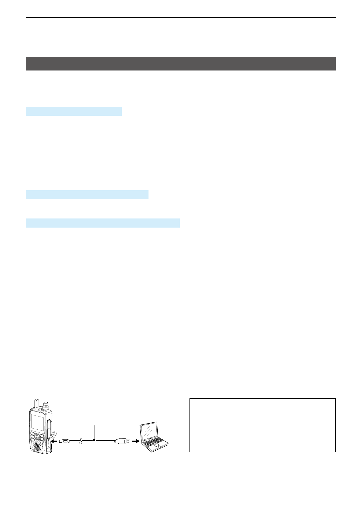
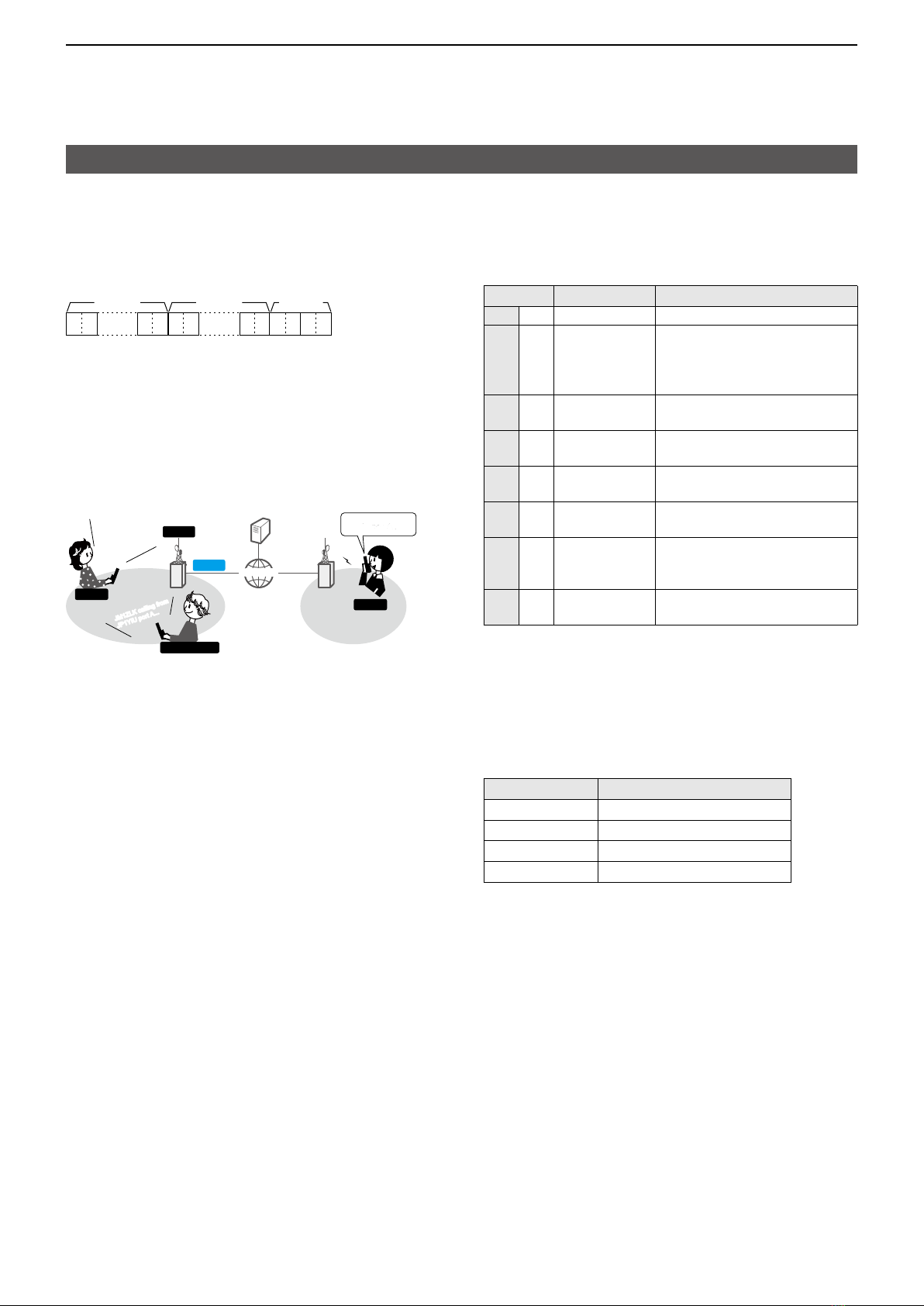
*2When sending the power ON command (18 01) using the [SP] jack
(p� 3), the command “FE” must be sent before the basic format�
The following is the approximate number of needed repetitions�
•4800bps: 15 “FE”s
•9600bps: 30 “FE”s
•19200bps: 60 “FE”s
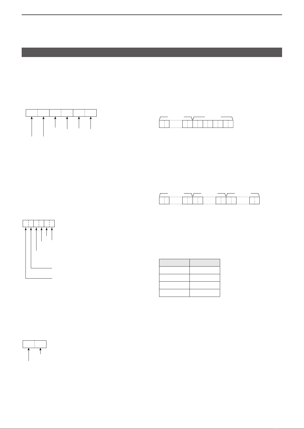
q w e r t u
Example: When operating with 4800 bps
×15
F 6AEFEF E E 10810 DF
1Preamble code (fixed) 2Transceiver’s default address
3Controller’s default address 4Command number
5Sub command number 7End of message code (fixed)
*3Output setting is automatically set to OFF after turning OFF the
transceiver�