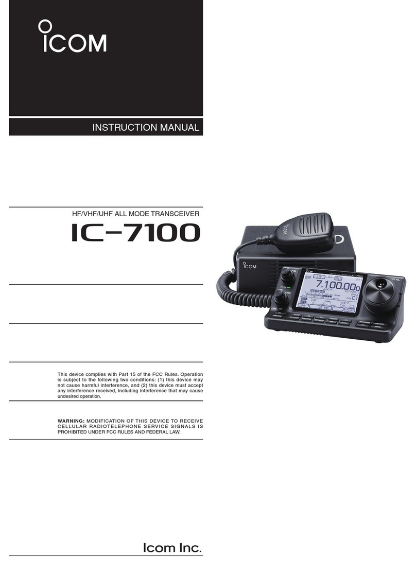
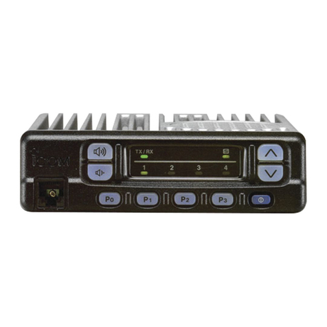
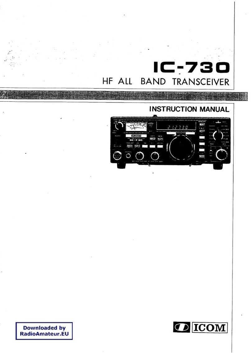
Icom IC-F50V User manual

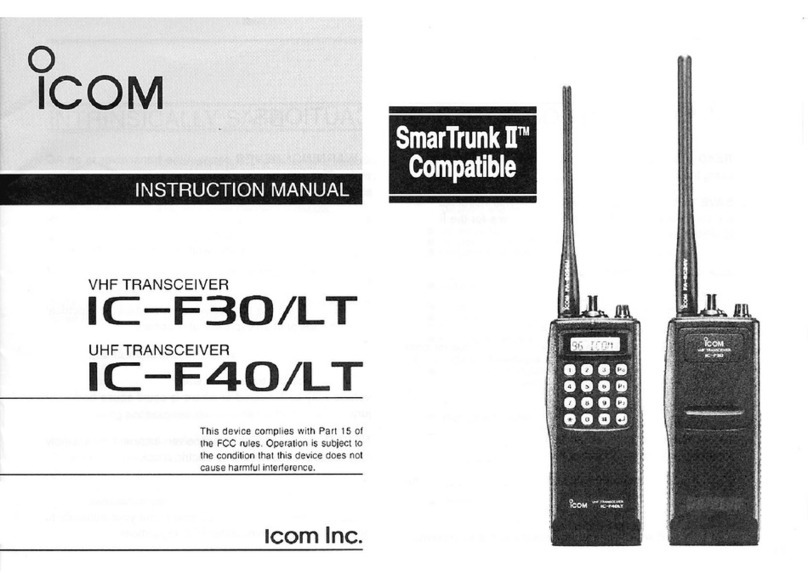
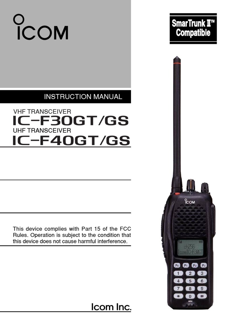
INSTRUCTION MANUAL
This device complies with Part 15 of the
FCC Rules. Operation is subject to the
condition that this device does not cause
harmful interference.
UHF TRANSCEIVER
iF60V
VHF TRANSCEIVER
iF50V

i
SAFETY TRAINING INFORMATION
Your Icom radio generates RF electromagnetic energy
during transmit mode. This radio is designed for and
classified as “Occupational Use Only”, meaning it
must be used only during the course of employment
by individuals aware of the hazards, and the ways to
minimize such hazards. This radio is NOT intended
for use by the “General Population” in an uncontrolled
environment.
This radio has been tested and complies with the FCC RF exposure
limits for “Occupational Use Only”. In addition, your Icom radio complies
with the following Standards and Guidelines with regard to RF energy
and electromagnetic energy levels and evaluation of such levels for
exposure to humans:
•FCCOETBulletin65Edition97-01SupplementC,Evaluating
Compliance with FCC Guidelines for Human Exposure to Radio
Frequency Electromagnetic Fields.
•AmericanNationalStandardsInstitute(C95.1-1992),IEEEStandard
for Safety Levels with Respect to Human Exposure to Radio
FrequencyElectromagneticFields,3kHzto300GHz.
•AmericanNationalStandardsInstitute(C95.3-1992),IEEE
Recommended Practice for the Measurement of Potentially
Hazardous Electromagnetic Fields– RF and Microwave.
•Thefollowingaccessoriesareauthorizedforusewiththisproduct.
Use of accessories other than those specified may result in RF
exposure levels exceeding the FCC requirements for wireless RF
exposure.;BeltClip(MB-98),RechargeableLi-ionBatteryPack(BP-
227),AlkalineBatteryCase(BP-226)andSpeaker-microphone
(HM-138/HM-168/HM-169/HM-170GP).
To ensure that your expose to RF electromagnetic
energy is within the FCC allowable limits for
occupational use, always adhere to the following
guidelines:
CAUTION
WARNING

SAFETY TRAINING INFORMATION
ii
•DO NOT operate the radio without a proper antenna attached, as
this may damaged the radio and may also cause you to exceed FCC
RF exposure limits. A proper antenna is the antenna supplied with
this radio by the manufacturer or antenna specifically authorized by
the manufacturer for use with this radio.
•DO NOTtransmitformorethan50%oftotalradiousetime(“50%
dutycycle”).Transmittingmorethan50%ofthetimecancauseFCC
RF exposure compliance requirements to be exceeded. The radio
is transmitting when the “TX indicator” lights red. You can cause the
radio to transmit by pressing the “PTT” switch.
•ALWAYS keeptheantennaatleast2.5cm(1inch)awayfrom
thebodywhentransmittingandonlyusetheIcombelt-clipwhich
islistedonpage38whenattachingtheradiotoyourbelt,etc.,
to ensure FCC RF exposure compliance requirements are not
exceeded. To provide the recipients of your transmission the best
soundquality,holdtheantennaatleast5cm(2inches)fromyour
mouth, and slightly off to one side.
The information listed above provides the user with the information
needed to make him or her aware of RF exposure, and what to do to
assure that this radio operates with the FCC RF exposure limits of this
radio.
Electromagnetic Interference/Compatibility
During transmissions, your Icom radio generates RF energy that can
possibly cause interference with other devices or systems. To avoid
such interference, turn off the radio in areas where signs are posted
to do so. DO NOT operate the transmitter in areas that are sensitive to
electromagnetic radiation such as hospitals, aircraft, and blasting sites.
Occupational/Controlled Use
The radio transmitter is used in situations in which persons are exposed
as consequence of their employment provided those persons are fully
aware of the potential for exposure and can exercise control over their
exposure.

iii
IMPORTANT
READ ALL INSTRUCTIONS carefully and completely before
using the transceiver.
SAVE THIS INSTRUCTION MANUAL— This instruction
manualcontainsimportantoperatinginstructionsfortheIC-F50V
v h f t r a n s c e i v e r andIC-F60Vu h f t r a n s c e i v e r .
EXPLICIT DEFINITIONS
WORD DEFINITION
RDANGER! Personal death, serious injury or an explo-
sion may occur.
RWARNING! Personal injury, fire hazard or electric shock
may occur.
CAUTION Equipment damage may occur.
NOTE
If disregarded, inconvenience only. No risk
of personal injury, fire or electric shock.
OPERATING NOTES
•Whentransmittingwithaportableradio,holdtheradioinavertical
positionwithitsmicrophone5to10cm(2to4inches)awayfromyour
mouth.Keeptheantennaatleast2.5cm(1inch)fromyourheadand
body.
•Ifyouwearaportabletwo-wayradioonyourbody,ensurethatthe
antennaisatleast2.5cm(1inch)fromyourbodywhentransmitting.
Icom, Icom Inc. and the Icom logo are registered trademarks of Icom Incorporated
(Japan)intheUnitedStates,theUnitedKingdom,Germany,France,Spain,Rus-
siaand/orothercountries.

iv
PRECAUTIONS
RDANGER! NEVER short the terminals of the battery pack.
RDANGER! Use and charge only specified Icom battery packs with
Icom radios or Icom chargers. Only Icom battery packs are tested and
approved for use with Icom radios or charged with Icom chargers. Using
third-partyorcounterfeitbatterypacksorchargersmaycausesmoke,
fire, or cause the battery to burst.
RWARNING! NEVER hold the transceiver so that the antenna is very
close to, or touching exposed parts of the body, especially the face or eyes,
while transmitting. The transceiver will perform best if the microphone is 5
to10cm(2to4inches)awayfromthelipsandthetransceiverisvertical.
RWARNING! NEVER operate the transceiver with a headset or
other audio accessories at high volume levels.
RCAUTION! NEVER connect the transceiver to a power source
otherthanthespeciedbatterypack/case.Suchaconnectionwillruin
the transceiver.
DO NOT push the PTT when not actually desiring to transmit.
DO NOT use or place the transceiver in direct sunlight or in areas with
temperaturesbelow–30°C(–22°F)orabove+60°C(+140°F).
DO NOT modify the transceiver for any reason. The transceiver war-
ranty does not cover any problems caused by unauthorized modification.
DO NOT operate the transceiver near unshielded electrical blasting
capsorinanexplosiveatmosphere.TheIC-F50V/F60Vseriestransceiv-
ersarenottheexplosion-proofconstruction.
MAKE SURE the flexible antenna and battery pack are securely at-
tached to the transceiver, and that the antenna and battery pack are dry
before attachment. Exposing the inside of the transceiver to water will
result in serious damage to the transceiver.
BE CAREFUL! ThetransceivermeetsIP67*requirementsfordust-
tight and waterproof protection. However, once the transceiver has been
dropped,dust-tightandwaterproofprotectioncannotbeguaranteedbe-
cause of possible damage to the transceiver’s case or the waterproof seal.
*Onlywhenthebatterypackandjackcoverareattached.

v
FCC INFORMATION
• FOR CLASS B UNINTENTIONAL RADIATORS:
This equipment has been tested and found to comply with the
limitsforaClassBdigitaldevice,pursuanttopart15oftheFCC
Rules. These limits are designed to provide reasonable protec-
tion against harmful interference in a residential installation. This
equipment generates, uses and can radiate radio frequency en-
ergy and, if not installed and used in accordance with the instruc-
tions, may cause harmful interference to radio communications.
However, there is no guarantee that interference will not occur in a
particular installation. If this equipment does cause harmful inter-
ference to radio or television reception, which can be determined
by turning the equipment off and on, the user is encouraged to try
to correct the interference by one or more of the following meas-
ures:
•Reorientorrelocatethereceivingantenna.
•Increasetheseparationbetweentheequipmentandreceiver.
•Connecttheequipmentintoanoutletonacircuitdifferent
from that to which the receiver is connected.
•Consultthedealeroranexperiencedradio/TVtechnicianfor
help.
• CAUTION:
Changes or modifications to this device, not expressly approved by
Icom Inc., could void your authority to operate this transceiver under
FCC regulations.

vi
TABLEOFCONTENTS
SAFETY TRAINING INFORMATION............................................................i
IMPORTANT............................................................................................... iii
EXPLICIT DEFINITIONS............................................................................ iii
OPERATING NOTES.................................................................................. iii
PRECAUTIONS..........................................................................................iv
FCC INFORMATION ...................................................................................v
TABLEOFCONTENTS..............................................................................vi
1 ACCESSORIES ................................................................................ 1−3
■ Supplied accessories .........................................................................1
■ Accessory attachments ......................................................................2
2 PANEL DESCRIPTION................................................................... 4−12
■ Front, top and side panels..................................................................4
■ Function display .................................................................................6
■ Programmable function keys..............................................................7
3 BASIC OPERATION ..................................................................... 13−22
■ Turning power ON.............................................................................13
■ Channel selection.............................................................................13
■ Call procedure ..................................................................................14
■ Receiving and transmitting ...............................................................15
■ User set mode ..................................................................................19
■ Emergency transmission ..................................................................20
■ Scrambler function ...........................................................................20
■ Stun function ....................................................................................20
■Recordingfunction(Dependsontheversion) ..................................21
4 BATTERY CHARGING ................................................................. 23−30
■ Caution.............................................................................................23
■ Optional battery chargers .................................................................26
5 BATTERY CASE........................................................................... 31−32
■Optionalbatterycase(BP-226) ........................................................31
6 SPEAKER-MICROPHONE........................................................... 33−34
■OptionalHM-168description............................................................33
■ Attachment .......................................................................................34
7 SWIVEL BELT CLIP ..................................................................... 35−36
■OptionalMB-86contents..................................................................35
■ Attaching ..........................................................................................35
■ Detaching .........................................................................................36
8 OPTIONS...................................................................................... 37−40
1ACCESSORIES
1
■Supplied accessories
Battery packAntenna
Belt clip
Key sticker*Jack cover
* There are no names on the programmable function keys since
thefunctionscanbefreelyassignedto[P0]to[P3],[Red],[ ]
and [ ]keys.
Attach the supplied key stickers above the appropriate keys for
easy recognition of that key’s assigned function.

■Accessory attachments
DFlexible antenna
Connect the supplied flexible antenna to the
antenna connector.
CAUTION:
•NEVER carry the transceiver by holding
only the antenna.
•DO NOT connect the anntena other
thanlistedonpage38.
•Transmitting without an antenna may
damage the transceiver.
DBattery pack
To attach the battery pack:
Slide the battery pack on the back of the transceiver in the direction
ofthearrow(q),thenlockitwiththebatteryreleasebutton.
•Slidethebatterypackuntilthebatteryreleasebuttonmakesa‘click’
sound.
To remove the battery pack:
Push the battery release
button in the direction of
thearrow(w)asshown
below. The battery pack
is then removed.
NOTE: Keep the bat-
tery terminals clean.
It’s a good idea to oc-
casionally clean them.
NEVER remove or attach the battery pack when the transceiver
is wet or soiled. This may result water or dust getting into the
transceiver/batterypackandmayresultinthetransceiverbeing
damaged.
q
w
Battery pack
Battery release button
2
1
ACCESSORIES
1
2
3
4
5
6
7
8
9
10
11
12
13
14
15
16
17
18
19
20

3
1ACCESSORIES
DJack cover
Attach the jack cover when the optional equipment is not used.
To attach the jack cover:
qInsert the jack cover into the
[SPMIC]jack.
wTighten the screw.
To detach the jack cover:
eRemove the screw using a
phillips screwdriver.
r
Detach the jack cover for the
optional equipment connection.
DBelt clip
Attach the belt clip to the back of the transceiver with the supplied
screws.
Supplied screws
w
Jack cover
[SP MIC] jack
Screw
q
e
r

4
2
PANEL DESCRIPTION
1
2
3
4
5
6
7
8
9
10
11
12
13
14
15
16
17
18
19
20
■Front, top and side panels
qVOLUME CONTROL [VOL]
Turns power ON and adjusts the audio level.
wRED BUTTON
Thedesiredfunctioncanbeassignedbyyourdealer.(p.7)
eANTENNA CONNECTOR
Connectsthesuppliedantenna.(p.2)
Microphone
Function display
(p. 6)
w
e
r
t
y
u
q
iSpeaker

5
2PANEL DESCRIPTION
rEXTERNAL SPEAKER-MICROPHONE JACK [SP MIC]
Connectstheoptionalspeaker-microphone,etc.
[SP MIC] jack cover
NOTE: KEEP the [SP MIC]
jack cover attached to the
transceiver when the optional
equipment is not used.
(See page 3 for details)
tDEALER-PROGRAMMABLE KEYS [P0] to [P3]
The desired functions can be assigned independently by your
dealer.(p.7)
yCH UP AND DOWN KEYS []/[]
Push to select an operating channel, etc.
*Desiredfunctionscanbeassignedindependentlybyyourdealer.
(p.7)
uTRANSMIT/BUSY INDICATOR
Lights red while transmitting; lights green while receiving a
signal, or when the squelch is open.
iPTT SWITCH [PTT]
➥Push and hold to transmit; release to receive.
➥Whentherecordingfunctionisactivated,TXvoicemessage
canberecordedwhilepushingandholding[PTT].(p.21)

6
2
PANEL DESCRIPTION
2
■Function display
u
o
qtiyrew
q RECORD INDICATOR
➥Appears when an unread message is in the memory.
➥Blinkswhilerecording.
w LOW POWER INDICATOR
Appears when low output power is selected.
eAUDIBLE INDICATOR
➥
Appearswhenthechannelisinthe‘audible’(unmute)condition.
➥Appearswhenthespecified2/5-tone/BIIS*1/MDC*2code is
received.
rCOMPANDER INDICATOR
Appears when the compander function is activated.
tKEY LOCK INDICATOR
Appears when the key lock function is activated.
ySCRAMBLER INDICATOR
Appears when the voice scrambler function is activated.
uBELL INDICATOR
Appears/blinkswhenthespecic2/5-tone/BIIS*1/MDC*2code is
received,accordingtothepre-programming.
iBATTERY INDICATOR
Appears or blinks when the battery power decreases to a
specified level.
oALPHANUMERIC DISPLAY
Displays an operating channel number, channel names, Set
mode contents, DTMF code, etc.
*1BIISoperationonly *2MDC operation only

7
2PANEL DESCRIPTION
■Programmable function keys
The following functions can be assigned to [P0], [P1], [P2], [P3],
[Red], [ ]and[ ]programmablefunctionkeys.
Consult your Icom dealer or system operator for details concern-
ing your transceivers programming.
If the programmable function names are bracketed in the following
explanations, the specific key is used to activate the function de-
pends on programming.
CH UP AND DOWN KEYS
➥Push to select an operating channel.
➥Push to select a transmit code channel after pushing [TX Code
CHSelect].
➥PushtoselectaDTMFchannelafterpushing[DTMFAutodial].
➥Push to select a scan group after pushing and holding [Scan A
Start/Stop]/[ScanBStart/Stop].
ZONE SELECT KEY
Pushthiskey,thenselectthedesiredzoneusing[CHUp]/[CH
Down].
What is a “zone”?—The desired channels are assigned into a
zone according to the intended use for grouping. For example,
‘StaffA’and‘StaffB’areassignedintoa“Business”zone,and
‘John’and‘Cindy’areassignedintoa“Private”zone.
SCAN A START/STOP KEY
➥This key’s operation depends on the Power ON Scan setting.
When the power ON scan function is turned OFF;
Push to start and cancel scanning operation.
When the power ON scan function is turned ON;
Push to pause scanning, then resumes scanning after a speci-
fied time period has passed.
➥Push and hold this key for 1 sec. to indicate the scan group, then
selectthedesiredscangroupusing[CHUp]/[CHDown].

8
2
PANEL DESCRIPTION
2
SCAN B START/STOP KEY
➥Push to start and cancel scanning operation. Scan resumes
after a specified time period has passed when scan is cancelled
except for this key.
➥Push and hold this key for 1 sec. to indicate the scan group, then
selectthedesiredscangroupusing[CHUp]/[CHDown].
SCAN ADD/DEL (TAG) KEY
➥Pushtoaddordeletetheselectedchannelto/fromthescan
group.
1.Pushtoindicatethescangroup,thenpush[CHUp]or[CHDown]
to select the desired group.
2.
Pushtoaddordeletethechannelto/fromtheselectedscangroup.
3. Push and hold for 1 sec. to exit the scan group selection mode.
➥Pushthiskeywhilescanispaused(asignalisdetected)on
achannel(exceptforprioritychannel,)thechanneliscleared
from the scan group.
Depending on the setting, the cleared channel is added to
thescangroupagainafterthescaniscancelled.(Nuisance
Deletefunction)
PRIORITY CHANNEL KEYS
➥PushtoselectPriorityAorPriorityBchannel.
➥Pushandhold[PrioA(Rewrite)]or[PrioB(Rewrite)]tosetthe
operatingchannelasthePriorityAorPriorityBchannel.
MR-CH 1/2/3/4 KEYS
Pushtoselectthememorychannel1to4directly.
LOCK KEY
Push and hold to toggle the key lock function ON or OFF.
•
All programmable keys except the followings are electronically locked
whenthekeylockfunctionisactivated:[PTT],[Light],[LoneWorker],[Sur-
veillance],[Call](incl.CallAandCallB),[Moni(Audi)]and[Emergency].

9
2PANEL DESCRIPTION
MONITOR KEY
➥MuteandreleasetheCTCSS(DTCS)or2-tonesquelchmute.
Openanysquelch/deactivateanymutewhilepushingandhold-
ing this key. (LMRoperationonly)
➥Activatesoneof(ortwoof)thefollowingfunctionsoneach
channel independently: (PMRoperationonly)
•Pushandholdtoun-mutethechannel(audioisemitted;‘Audible’
condition).
•Pushtomutethechannel(setsto‘Inaudible’only).
•Pushafterthecommunicationisfinishedtosenda‘resetcode’.
(BIISoperationonly)
NOTE:Theun-mutecondition(‘Audible’condition)mayauto-
maticallyreturntothemutecondition(‘Inaudible‘condition)
after a specified period.
LIGHT KEY
Push to turn the backlight ON for about 5 sec. even if the backlight
function is turned OFF in the User Set mode.
LONE WORKER KEY
PushtoturntheLoneWorkerfunctionONorOFF.
•IftheLoneWorkerfunctionisactivated,theEmergencyfunctionis
automatically turned ON after the specified time period has passed
with no operation is performed.
HIGH/LOW KEY
Push to select the transmit output power temporarily or perma-
nently,dependingonthepre-setting.
•Askyourdealerfortheoutputpowerlevelforeachselection.
C.TONE CHANNEL ENTER KEY
Push to enter the continuous tone channel selection mode, and
push[CHUp]/[CHDown]tochangethetonefrequency/codeset-
ting. The selected channel remains set as the continuous tone
channel until another channel is designated as such.

10
2
PANEL DESCRIPTION
2
TALK AROUND KEY
Push to turn the talk around function ON and OFF.
•Thetalkaroundfunctionequalizesthetransmitfrequencytothere-
ceivefrequencyfortransceiver-to-transceivercommunication.
WIDE/NARROW KEY
Push to toggle the IF bandwidth between wide and narrow.
•Thewidepassbandwidthcanbeselectedfrom25.0or20.0kHz
usingtheCS-F50Vcloning software.(PMRoperationonly)Ask
your dealer for details.
DTMF AUTODIAL KEY
➥Push to enter the DTMF channel selection mode. Then select
thedesiredDTMFchannelusing[CHUp]/[CHDown].
➥After selecting the DTMF channel, push again to transmit the
selected DTMF code.
DTMF RE-DIAL KEY
Pushtotransmitthelast-transmittedDTMFcode.
•TXmemoriesareclearedafterturningthetransceiverOFF.
CALL KEYS
Pushtotransmita2/5-tone/BIISIDcode.
•Calltransmissionisnecessarybeforecallinganotherstationdepend-
ing on your signalling system.
•[CallA]and/or[CallB]maybeavailablewhenyoursystememploys
selective‘Individual/Group’calls.Askyourdealerwhichcallisas-
signed to each key.
SURVEILLANCE KEY
Push to turn the surveillance function ON or OFF.
WhenthisfunctionisturnedON,thebeepisnotemittedandthe
LCD backlight and the LED indicator do not light when a signal is
received or a key is pushed.

11
2PANEL DESCRIPTION
EMERGENCY KEYS
Push and hold to transmit the emergency call.
•Theemergencycalltransmitswithbeeps;thedisplaydoesnot
change.
•Thetransceivercantransmittheemergencycallsilentlyorwiththe
displaychangesdependingonthepre-setting.Askyourdealerfor
details.
•Ifyouwanttocanceltheemergencycall,pushandholdthekey
again before transmitting the call.
•Theemergencycallistransmittedonetimeonlyorrepeatedlyuntil
receivingacontrolcode,dependingonthepre-setting.
TX CODE ENTER KEY (PMRoperationonly)
Push to enter the TX code edit mode. Then set the desired digit
using[CHUp]/[CHDown].(p.18)
TX CODE CHANNEL SELECT KEY
➥Push to enter the TX code channel selection mode. Then select
thedesiredchannelusing[CHUp]/[CHDown].(p.17)
➥WhileintheTXcodechannelselectionmode,pushandholdfor
1 sec. to enter the TX code edit mode. Then set the desired digit
using[CHUp]/[CHDown].(p.17;PMRoperationonly)
TX CODE CHANNEL UP/DOWN KEYS
Push to select a TX code channel directly.
ID-MR SELECT KEY(PMRoperationonly)
➥Recalls detected ID codes.
•Pushthiskey,thenpush[CHUp]/[CHDown]forselection.
•Upto5ID’sarememorized.
➥Push and hold to erase the selected memorized ID’s.
VOICE SCRAMBLER FUNCTION
Push to turn the voice scrambler function ON and OFF.

12
2
PANEL DESCRIPTION
1
2
3
4
5
6
7
8
9
10
11
12
13
14
15
16
17
18
19
20
COMPANDER KEY
Push to turn the compander function ON and OFF.
The compander function reduces noise components from the
transmitting audio to provide clearer communication.
USER SET MODE KEY
➥Push and hold to enter the User Set mode.
•IntheUserSetmode,pushthiskeytoselectanitemthatisena-
bled by your dealer, and change the value or condition by pushing
[CHUp]or[CHDown].
➥Push and hold this key again to exit the User Set mode.
PLAYBACK KEY(p.22)
➥Push to playback the recorded messages in sequence, starting
with the latest one.
•Ashortbeepisemittedafterplayingbackeachmessage.
•Alongbeepisemittedafterplayingbackallmessages.
•Anerrorbeepisemittedwhentherearenomessagesinthe
memory.
➥Whileplayingbackthemessage,pushandholdfor1sec.to
delete the selected message.
PLAYBACK/REC KEY(pp.21,22)
➥Push to playback the recorded messages in sequence, starting
with the latest one.
•Ashortbeepisemittedafterplayingbackeachmessage.
•Alongbeepisemittedafterplayingbackallmessages.
•“NO REC” is displayed when no message is in the memory.
➥Push and hold for 1 sec. to start recording. Push again to stop
recording.
➥Whileplayingbackthemessage,pushandholdfor1sec.to
delete the selected message.

13
3BASIC OPERATION
■Turning power ON
qRotate[VOL]toturnpowerON.
•WhentheopeningvibrationfunctionisturnedON,thetransceiver
vibratesfor2sec.Askyourdealerfordetails.
wIf the transceiver is programmed for a start up passcode, input
digit codes as directed by your dealer.
•Thekeysinthetablebelowcanbeusedforpasswordinput:
•Thetransceiverdetectsnumbersinthesameblockasidentical.
Therefore“01234”and“56789”arethesame.
KEY
NUMBER 0
5
4
9
3
8
2
7
1
6
or
eWhenthe“PASSWORD”indicationdoesnotclearafterinput-
ting4digits,theinputcodenumbermaybeincorrect.Turnthe
power off and start over in this case.
■Channel selection
Several types of channel selections are available. Methods may
differ according to your system set up.
NON-ZONE TYPE:
Push[CHUp]/[CHDown]toselectthedesiredoperatingchannel
insequence;or,pushoneof[MR-CH1]to[MR-CH4]toselecta
channel directly.
ZONE TYPE:
Push[Zone]thenpush[CHUp]/[CHDown]toselectthedesiredzone.
AUTOMATIC SCAN TYPE:
Channelsettingisnotnecessaryforthistype.Whenturningthe
power ON, the transceiver automatically starts scanning. Scanning
stops when receiving a call.
Other manuals for IC-F50V
2
This manual suits for next models
1
Table of contents
Other Icom Transceiver manuals