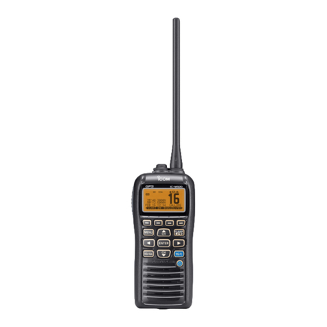
Icom IC-F5360D User manual

OPERATING INSTRUCTIONS
iF5360D
8
NXDN OPERATION <CONVENTIONAL MODE>
7
NXDN OPERATION <TRUNKING MODE>
6 NXDN OPERATION <COMMON>
5 MENU SCREEN
4 SCAN OPERATION
3 ADVANCED OPERATION
2 BASIC OPERATION
1 PANEL DESCRIPTION
INTRODUCTION
VHF DIGITAL TRANSCEIVERS
iF6360D
UHF DIGITAL TRANSCEIVERS

i
INTRODUCTION
FOREWORD
Thank you for purchasing this Icom transceiver.
The IDAS™NXDN™system operation is built into your
IC-F5360D v h f digital t r a n s c e i v e r s and IC-F6360D
u h f digital t r a n s c e i v e r s .
IMPORTANT
FIRST, CAREFULLY READ INSTRUCTIONS
qPRECAUTIONS and wINSTRUCTIONS that are
provided with the transceiver.
SAVE THIS OPERATING INSTRUCTIONS—
This operating instructions contain additional important
operating instructions for the IC-F5360D v h f digital
t r a n s c e i v e r s and IC-F6360D u h f digital t r a n s c e i v -
e r s .
NOTE
The display contents, and the hold down time period of
some keys, may vary from the description in this manu-
al, depending on the transceiver’s presetting.
Icom, Icom Inc. and the Icom logo are registered trademarks
of Icom Incorporated (Japan) in Japan, the United States,
the United Kingdom, Germany, France, Spain, Russia and/
or other countries.
IDAS is trademark of Icom Incorporated (Japan).
NXDN is a trademark of Icom Incorporated and JVC KEN-
WOOD Corporation.
All other products or brands are registered trademarks or
trademarks of their respective holders.

1-1
Section 1PANEL DESCRIPTION
Front, top and side panels......................................................1-2
About the MicrophoneD.............................................................1-2
About the SpeakerD...................................................................1-2
Function display ......................................................................1-3
Programmable function keys .................................................1-4

1PANEL DESCRIPTION
1-2
Front, top and side panels
qLED INDICATOR
Lights red while transmitting.➥
Lights green while receiving a signal, or when the➥
squelch is open.
wFUNCTION DISPLAY (p. 1-3)
Displays a variety of information.
eDEALER-PROGRAMMABLE KEYS
[UP] and [DOWN]
Desired functions can be preset.
(p. 1-5)
rPOWER KEY [ ]
Push and hold for 1 second to turn the power ON
and OFF.
tDEALER-PROGRAMMABLE KEYS
[R], [P0], [P1], [P2], [P3]
Desired functions can be preset.
(p. 1-5)
yMICROPHONE CONNECTOR
Connect the supplied or optional microphone.
NEVER connect non-specified microphones. The
pin assignments may be different and the trans-
ceiver may be damaged.
uAF VOLUME CONTROL KNOB [VOL]
Rotate to adjust the audio output level.
About the MicrophoneD
The supplied or optional microphone has a PTT switch
and a hanger hook.
• The following functions are available when the micro-
phone is on or off hook (depending on the presetting):
- Pauses scan when it is off-hook.
- Switches to the ‘Inaudible’ mode (mute mode) when
it is on-hook.
- Switches to the ‘Audible’ mode (unmute mode)
when it is off-hook.
About the SpeakerD
The speaker will be disabled when the External speak-
er function is ON. (pp. 1-6, 5-3)
uAF VOLUME
CONTROL
KNOB [VOL]
qLED INDICATOR eDEALER PROGRAMMABLE KEYS
[UP], [DOWN]
rPOWER KEY [ ]
tDEALER-PROGRAMMABLE KEYS
[R], [P0], [P1], [P2], [P3]
wFUNCTION DISPLAY
SPEAKER
yMICROPHONE
CONNECTOR

1PANEL DESCRIPTION
1-3
Function display
qSIGNAL STRENGTH INDICATOR
Displays the relative receive signal strength.
wLOW OUTPUT POWER ICON
Displayed when low output power is selected.
eAUDIBLE ICON
Displayed when the channel is in the ‘audible’ (un-
mute) mode.
r SCRAMBLER ICON
Displayed when the Voice Scrambler function is ON.
t SCAN ICON
Displayed while scanning.
y MESSAGE ICON
Displayed when a received message (Short Data➥
Message or Status Message) is stored in the
memory stack.
Blinks when an unread message is in the memory➥
stack.
u BELL ICON
Blinks when a matched signal is received, depend-
ing on the presetting.
i GPS ICON
Displayed when position data is received.
o HORN ALERT ICON
Displayed when the Horn Alert function is ON.
!0 PUBLIC ADDRESS ICON
Displayed when the Public Address function is ON.
!1 ALPHANUMERIC READOUT
Displays the operating channel number, channel
name, menu contents, DTMF code, and so on.
• The display mode automatically switches between one
line and two lines.
!2 KEY ICONS
Display the assigned function of the [P0], [P1], [P2]
and [P3] dealer assignable keys.
!3 SCAN TARGET ZONE ICON
Displayed when the scan target zone is selected.
!4 PA SPEAKER ICON
Displayed when the External speaker function is ON.
When the External speaker function is ON, the PA
speaker that is connected to the D-Sub 15-pin will be
enabled.
!5 AUX A ICON
Displayed when the AUX A port is activate.
!6 AUX B ICON
Displayed when the AUX B port is activate.
!7 SCAN TARGET CHANNEL ICON
Displayed when the scan target channel is selected.
!8 OPERATOR SELECTABLE TONE ICON
Displayed when the OST (Operator Selectable Tone)
function is ON.
IC-F5360D
CONTACT
①縦横比を52×1 9にする。
②拡大200%
③拡大150%
qw e r t y u i o !0
!2
!1 !3 !4 !5 !6 !7 !8

1PANEL DESCRIPTION
1-4
Programmable function keys
The programmable key functions can be assigned to
the following keys:
[R], [P0], [P1], [P2], [P3], [UP], [DOWN] and to the key-
pad keys of the optional DTMF microphone.
[UP], [DOWN]
[R], [P0], [P1], [P2], [P3]

1PANEL DESCRIPTION
1-5
Programmable function keys (Continued)
• For [R], [P0], [P1], [P2], [P3], [UP] and [DOWN]
The key names that are in quotation marks in the fol-
lowing explanations are displayed on the Function Dis-
play, and indicate the assigned function of [P0], [P1],
[P2] and [P3].
None
No function
Autodial “ADAL” (p. 3-2)
Opens the DTMF Autodial code selection screen.
Autodial Programming “ADPG” (p. 3-3)
Enters the DTMF code programming mode.
AUX A “AUXA”
Turns the AUX A port ON or OFF.
AUX B “AUXB”
Turns the AUX B port ON or OFF.
Broadcast “BCST”
Toggles between Broadcast Call and Conference Call.
This key can also be used to make a Broadcast Group
Call.
Call 1 “CAL1”
Sends the NXDN Status, NXDN Individual or the DTMF
code that is set to Call 1.
Call 2 “CAL2”
Sends the NXDN Status, NXDN Individual or the DTMF
code that is set to Call 2.
Call 3 “CAL3”
Sends the NXDN Status, NXDN Individual or the DTMF
code that is set to Call 3.
Call 4 “CAL4”
Sends the NXDN Status, NXDN Individual or the DTMF
code that is set to Call 4.
Call 5 “CAL5”
Sends the NXDN Status, NXDN Individual or the DTMF
code that is set to Call 5.
Call 6 “CAL6”
Sends the NXDN Status, NXDN Individual or the DTMF
code that is set to Call 6.
CH/GID Down “CH D”
Selects the next or previous channel or GID number.
CH/GID Recall “CHRC”
❍In the Analog mode or
NXDN Conventional system
Selects the last used channel during a scan.
❍
In the NXDN Trunking system
Selects the last called GID during a scan.
CH/GID Up “CH U”
Selects the next or previous channel or GID number.
Channel Entry “CHEN” (p. 2-4)
Enters the Channel Entry mode.
CW Message “CWMS”
Sends a preset CW Message on a ‘very narrow’ chan-
nel.
You can use this function when a CW message is pre-
set.
Direct CH/GID 1 “DR 1” (pp. 2-4, 7-3)
Selects the channel or GID that is set to Direct CH/
GID 1.
Direct CH/GID 2 “DR 2” (pp. 2-4, 7-3)
Selects the channel or GID that is set to the Direct CH/
GID 2.
Direct CH/GID 3 “DR 3” (pp. 2-4, 7-3)
Selects the channel or GID that is set to Direct CH/
GID 3.
Direct CH/GID 4 “DR 4” (pp. 2-4, 7-3)
Selects the channel or GID that is set to Direct CH/
GID 4.
Direct CH/GID 5 “DR 5” (pp. 2-4, 7-3)
Selects the channel or GID that is set to Direct CH/
GID 5.
Direct CH/GID 1 Select
This function is for the hold down operation of [Direct
CH/GID 1].
Sets the selected channel or GID to Direct CH/GID 1.

1PANEL DESCRIPTION
1-6
Programmable function keys
Direct CH/GID 2 Select
This function is for the hold down operation of [Direct
CH/GID 2].
Sets the selected channel or GID to Direct CH/GID 2.
Direct CH/GID 3 Select
This function is for the hold down operation of [Direct
CH/GID 3].
Sets the selected channel or GID to Direct CH/GID 3.
Direct CH/GID 4 Select
This function is for the hold down operation of [Direct
CH/GID 4].
Sets the selected channel or GID to Direct CH/GID 4.
Direct CH/GID 5 Select
This function is for the hold down operation of [Direct
CH/GID 5].
Sets the selected channel or GID to Direct CH/GID 5.
Display Format “DISP”
❍In the Analog mode or
NXDN Conventional system
Toggles the display format between the channel name
and the zone and channel number.
❍
In the NXDN Trunking system
Toggles the display format between the GID name and
the GID number.
Emergency (p. 3-5)
This function can be assigned only for [R].
Enters the Emergency mode.
External Speaker “EXSP”
Turns the External speaker function ON or OFF.
When the External speaker function is ON, the PA
speaker that is connected to the D-Sub 15-pin will be
enabled.
• In this case, the front panel speaker and the speaker that is
connected to the external speaker jack will be disabled.
Fixed Volume “FIXV”
Toggles the tone level between “High” and “Low,” or
turns OFF the tone.
Forced Search “FORS”
Displays the site number of the current site for 2 sec-
onds.
Forced Search Function
This function is for the hold down operation of [Forced
Search].
Activates a Control Channel Hunt.
Function “FUNC”
Activates a secondary function that is assigned to a
key.
This function cannot be assigned as a secondary func-
tion.
GPS Position Display “GPSP”
Enters the GPS Position Display mode.
In the GPS Position Display mode, you can check your
latitude and longitude position.
Group ID/Channel Entry “GIDE” (pp. 2-4, 7-3)
❍In the Analog mode or
NXDN Conventional system
Enters the Channel Entry mode.
❍
In the NXDN Trunking system
Enters the GID Entry mode.
Group (NXDN) “GRP” (pp. 7-4, 8-3)
❍In the NXDN Conventional system or
the NXDN Trunking system
Enters the Group Call mode.
In the NXDN Conventional system, this function is used
for Group Call by recalling GID list.
In the NXDN Trunking system, the GID List is displayed,
but the transceiver cannot make a call.
Group + SDM (NXDN) “GSMS”
❍In the NXDN Conventional system or
the NXDN Trunking system
Enters the Group Call mode.
If you push [P1](ENT) while in the Group Call mode,
the transceiver enters the Short Data Message Entry
mode. See page 7-4 or 8-3 for details.
Group + Status (NXDN) “GSTA”
❍In the NXDN Conventional system or
the NXDN Trunking system
Enters the Group Call mode.
If you push [P1](ENT) while in the Group Call mode,
the transceiver enters the Status Message Entry mode.
See page 7-4 or 8-3 for details.
High Transmit Power “HIPW”
❍
In the NXDN Trunking system
Toggles the transmit power level between “High” and➥
“Auto,” if “Auto” is set as the default.
Toggles the transmit power level between “High” and➥
“Low,” if “Low” is set as the default.
• For [R], [P0], [P1], [P2], [P3], [UP] and [DOWN] (Continued)

1PANEL DESCRIPTION
1-7
Programmable function keys
Home CH/GID “HOME” (pp. 2-4, 7-3)
❍In the Analog mode or
NXDN Conventional system
Selects the Home Channel.
❍
In the NXDN Trunking system
Selects the Home GID.
Home CH/GID Select (pp. 2-4, 7-3)
This function is for the hold down operation of [Home
CH/GID].
❍In the Analog mode or
NXDN Conventional system
Sets the selected channel as the Home Channel.
❍
In the NXDN Trunking system
Sets the selected GID as the Home GID.
Horn Alert “HORN”
Turns the Horn Alert function ON or OFF.
When this function is ON, the horn alert port will be ac-
tivated for a preset time period after receiving a call.
Individual (NXDN) “INDV” (pp. 7-5, 7-6, 8-4)
❍In the NXDN Conventional system or
the NXDN Trunking system
Enters the Individual Call mode.
Individual + SDM (NXDN) “ISMS”
❍In the NXDN Conventional system or
the NXDN Trunking system
Enters the Individual Call mode.
If you push [P1](ENT) while in the Individual Call mode,
the transceiver enters the Short Data Message Entry
mode. See page 7-5 or 8-4 for details.
Individual + Status (NXDN) “ISTA”
❍In the NXDN Conventional system or
the NXDN Trunking system
Enters the Individual Call mode.
If you push [P1](ENT) while in the Individual Call mode,
the transceiver enters the Status Message Entry mode.
See page 7-5 or 8-4 for details.
LCD Brightness “BRIT”
Selects the brightness of the function display and keys
backlight. Select High, Low or OFF to meet your needs.
The function display and keys can be backlit for better
visibility under low light conditions.
Lone Worker “LONE” (p. 3-5)
Turns the Lone Worker function ON or OFF.
Low Transmit Power “LOPW”
❍In the Analog mode or
NXDN Conventional system
Toggles the transmit power between “High” and “Low,” if
“High” is set as the default.
❍
In the NXDN Trunking system
Toggles the transmit power level between “Low” and➥
“Auto,” if “Auto” is set as the default.
Toggles the transmit power level between “High” and➥
“Low,” if “High” is set as the default.
Maintenance “MANT”
Enters the Maintenance Display mode.
Menu “MENU” (p. 5-2)
Displays the Menu screen.
Monitor “MONI”
❍In the Analog mode
Turns the Monitor ON or OFF.
When the Monitor is ON, the transceiver releases the
CTCSS or DTCS mute.
❍In the NXDN Conventional system
Turns the Monitor ON or OFF.
When the Monitor is ON, the transceiver releases the
RAN code mute.
Monitor Momentary “MONI”
❍In the Analog mode
While holding down, the transceiver releases the CTC-
SS mute.
❍In the NXDN Conventional system
While holding down, the transceiver releases the RAN
code mute.
Operator Selectable Tone “OST”
Turns the OST (Operator Selectable Tone) mode ON
or OFF.
When the OST mode is ON, the selected tone in the
OST list is enabled.
OST List
This function is for the hold down operation of [Opera-
tor Selectable Tone].
Displays the OST (Operator Selectable Tone) list.
Priority-channel Select “PRIO”
Enters the Priority channel Select mode for a Priority
scan.
• For [R], [P0], [P1], [P2], [P3], [UP] and [DOWN] (Continued)
1PANEL DESCRIPTION
1-8
Programmable function keys
Public Address “PUBA”
Turns the Public Address function ON or OFF.
When this function is ON, you can make announce-
ment through a PA speaker.
• Transmitting is disabled while in the PA mode.
Scan “SCAN”
Starts or stops a scan.
Scan Delete/Add “SCNE”
Sets or cancels the selected channel or GID as a scan
target.
Scrambler/Encryption “SCRM”
❍In the Analog mode
Turns the Scrambler function ON or OFF.
❍In the NXDN Conventional system or
the NXDN Trunking system
Turns the Encryption function ON or OFF.
Scrambler/Encryption Code
This function is for the hold down operation of [Scram-
bler/Encryption].
❍In the Analog mode
Enters the Scrambler Code mode.
❍In the NXDN Conventional system or
the NXDN Trunking system
Enters the Encryption Code mode.
SDM (NXDN) “SMSG”
❍In the NXDN Conventional system or
the NXDN Trunking system
Directly enters the Short Message mode.
Push [PTT] to send a Short Message to a Base ID.
Send the GPS data “GPSD”
❍In the NXDN Conventional system or
the NXDN Trunking system
Sends the position data that is received from the GPS
receiver to a Base station.
Site Down “SIDN”
❍
In the NXDN Trunking system
Selects the previous site number.
If the site name is not entered, [Site Down] does not
function.
Site Lock “SILK”
❍
In the NXDN Trunking system
Turns the Site Lock function ON or OFF.
Site Select
This function is for the hold down operation of [Site
Lock].
❍
In the NXDN Trunking system
Enters the Site Select mode.
If the site name is not entered, [Site Select] does not
function.
Site Up “SITU”
❍
In the NXDN Trunking system
Selects the next site number.
If the site name is not entered, [Site Up] does not func-
tion.
Squelch Level “SQLL”
❍In the Analog mode
Enters the Squelch Level Adjustment mode.
Squelch Off “SQLO”
❍In the Analog mode or
NXDN Conventional system
Opens the squelch, and releases the mute.
Squelch Off Momentary “SQLM”
❍In the Analog mode or
NXDN Conventional system
While holding down, opens the squelch, and releases
the mute.
Stack “STAK” (p. 6-3)
Enters the Memory Stack mode.
Status (NXDN) “STAT”
Enters the Status Message mode.
Push [PTT] to send a Status to a Base ID.
Talk Around “TLKA”
Turns the Talk around function ON or OFF.
• The Talk around function equalizes the transmit frequency
to the receive frequency for transceiver-to-transceiver com-
munication.
Transceiver Password “PSWD” (p. 2-2)
Enters the password entry mode.
The transceiver cannot be used until you enter a cor-
rect password.
Zone Delete/Add “ZODE”
Sets or cancels the selected zone as a scan target.
Zone Down “ZNDN”
Selects the previous zone number.
Zone Up “ZNUP”
Selects the next zone number.
• For [R], [P0], [P1], [P2], [P3], [UP] and [DOWN] (Continued)
1PANEL DESCRIPTION
1-9
• For Keypad Operation (Microphone)
Channel Entry (p. 2-4)
Enters the channel number.
Group ID/Channel Entry (pp. 2-4, 7-3)
❍In the Analog mode
❍In the NXDN Conventional system
Enters the channel number.
❍
In the NXDN Trunking system
Enters the GID.
OST (Operator Selectable Tone)
Hold down [1] to [9] to select a tone that is preset in➥
the OST list.
Hold down [0] to turn OFF the OST tone.➥
Hold down [➥M] to turn OFF the OST mode.
• When the OST mode is OFF, the selected channel’s pre-
set tone is used.
Hold down [#], and then push the [0] to [9] digit keys➥
to enter the OST List number 1 to 40 to select a pre-
set tone.
Autodial
Selects the DTMF Code that is preset in the Autodial
List.
After selecting, push [PTT] to send.
Keypad Auto PTT
Transmits DTMF tones.
This function is enabled only when Manual Dialing is
enabled.
Status (NXDN)
❍In the NXDN Conventional system
❍
In the NXDN Trunking system
Enters the Status Message mode, and selects the Sta-
tus number.
SDM (NXDN)
❍In the NXDN Conventional system
❍
In the NXDN Trunking system
Enter an SDM message.
Individual (NXDN)
❍In the NXDN Conventional system
❍
In the NXDN Trunking system
Enters the Individual Call mode, and selects the unit ID
to send an Individual Call to.
Individual + Status (NXDN)
❍In the NXDN Conventional system
❍
In the NXDN Trunking system
Enters the Individual Call mode, and selects the unit ID
to transmit an Individual Call to.
If you push [P1](ENT) while in the Individual Call mode,
the transceiver enters the Status Message mode.
Individual + SDM (NXDN)
❍In the NXDN Conventional system
❍
In the NXDN Trunking system
Enters the Individual Call mode, and selects the unit ID
to transmit an Individual Call to.
If you push [P1](ENT) while in the Individual Call mode,
the transceiver enters the Short Data Message mode.
Group (NXDN)
❍In the NXDN Conventional system
Enters the Group Call mode, and selects the GID to
send a Group Call to.
❍
In the NXDN Trunking system
Displays the GID List, but the transceiver cannot make
a call.
Group + Status (NXDN)
❍In the NXDN Conventional system
❍
In the NXDN Trunking system
Enters the Group Call mode, and selects the GID to
transmit a Group Call to.
If you push [P1](ENT) while in the Group Call mode, the
transceiver enters the Status Message mode.
Group + SDM (NXDN)
❍In the NXDN Conventional system
❍
In the NXDN Trunking system
Enters the Group Call mode, and selects the GID to
transmit a Group Call to.
If you push [P1](ENT) while in the Group Call mode, the
transceiver enters the Short Data Message mode.
Programmable function keys (Continued)

2-1
Section 2BASIC OPERATION
Turning power ON....................................................................2-2
Adjusting the audio levelD..........................................................2-2
Inputting the passwordD............................................................2-2
Selecting a zone ......................................................................2-3
Selecting a zoneD......................................................................2-3
Selecting a channel.................................................................2-4
Selecting a channelD.................................................................2-4
Selecting a Home channelD......................................................2-4
Directly entering a channelD......................................................2-4
Receiving..................................................................................2-5
Setting the squelch levelD..........................................................2-5
Transmitting .............................................................................2-6
Transmitting notesD...................................................................2-6

2BASIC OPERATION
2-2
Turning power ON
Hold down [➥] for 1 second to turn ON the power.
Adjusting the audio levelD
When receiving a call, rotate [VOL] to adjust the au-➥
dio output volume level.
Inputting the passwordD
If the transceiver is preset for a start up password, en-
ter the digit codes.
While in the Password Entry mode, “PASSWORD”q
is displayed.
Push [UP] or [DOWN] to enter a digit code, and thenw
push [P1] to set.
• Goes to the next digit entry position.
Repeat stepe w until you enter the password, and
then push [P1].
When using the DTMF microphone:
Push the [0] to [9] digit keys on the microphone to enter
the password, and then push [#].
NOTE: If “PASSWORD” does not disappear after
pushing [P1], the password code you entered may
be incorrect. In this case, enter the correct pass-
word.
For your reference:
When [Transceiver Password] is assigned to any key,
or the Transceiver Password item is preset in the
Menu screen and [Menu] is assigned to any key, the
start up password does not appear, even if the Trans-
ceiver Password is programmed.
In this case, push [Transceiver Password], or select
“Transceiver Password” in the Menu screen to enter
the Password Entry mode, then enter the password
as described above.
PASSWORD
12345
Channel 1
[VOL] [ ]
[P1] [UP] [DOWN]

2BASIC OPERATION
2-3
Selecting a zone
Selecting a zoneD
To select a desired zone (Conventional group or NXDN
Trunking system).
Push [Zone Up] or [Zone Down].➥
NOTE:
When you select the Conventional group zone, see
the page 2-4 for details of the channel selection.
When you select the NXDN Trunking system zone,
see page 7-3 for details of the GID (Group ID) selec-
tion.
For your reference: What is “zone?”
Certain channels are grouped together and assigned
to a zone according to their intended use.
For example, ‘Staff A’ and ‘Staff B’ are assigned to a
“Business” zone, and ‘John’ and ‘Cindy’ are assigned
to a “Private” zone.

2BASIC OPERATION
2-4
Selecting a channel
Selecting a channelD
To select a desired operating channel:
Push [CH/GID Up] or [CH/GID Down].➥
Push one of the direct channel select keys, [Direct➥
CH/GID 1] to [Direct CH/GID 5].
• You can change the channel by pushing [Direct CH/GID
1] to [Direct CH/GID 5], as described below.
Changing the Direct channel setting:
Select a desired channel.q
Hold down one of the [Direct CH/GID 1] to [Directw
CH/GID 5] keys for 3 seconds to set the selected
channel to the Direct channel 1 to 5.
Directly entering a channelD
You can select a channel by pushing [UP] or [DOWN] or
the [0] to [9] digit keys on the microphone, after pushing
[Channel Entry].
Or, when the Channel Entry function is assigned to the
keypad, you can select a channel by pushing [0] to [9]
digit keys on the microphone.
Push [Channel Entry] to enter the Channel Entryq
mode.
CH ENTER MOD
CH No. _ _
w
Push [UP] or [DOWN] to select
the channel number,
and then push [P1](SEL).
• Push [P0](BACK) to cancel the entry, and return to the
screen that you selected before entering the Channel En-
try mode.
• You can use the digit keys on the microphone.
Channel 1
When using the DTMF microphone:
Push the [0] to [9] digit keys to enter the Channelq
Entry mode.
CH ENTER MOD
CH No. _ 1
Enter the channel number, and then push [#].w
• Push [M] to delete the entered number.
• Push [M] again to cancel the entry, and return to the
screen that you selected before entering the Channel
Entry mode.
Channel 1
•When the channel name is not programmed, the
selected zone and channel number are displayed.
(example: “1- 1”)
•When the programmed channel is less than 10, you
can select a channel without pushing [#].
Selecting a Home channelD
The Home channel is an often-used Memory channel
you can preset in the transceiver.
Push [Home CH/GID].➥
• To change the Home channel, see the description
below.
Changing the Home channel setting:
Select a desired channel.q
Hold down [Home CH/GID Select] for 3 seconds tow
set the selected channel as the Home channel.
For your reference:
You may be able to select a channel in the Menu
screen, depending on the presetting.
See section 5 for details.

2BASIC OPERATION
2-5
Receiving
Select a channel. (p. 2-4)q
Push [CH/GID Up] or [CH/GID Down].➥
Push one of the direct channel select keys, [Direct➥
CH/GID 1] to [Direct CH/GID 5].
Push the [0] to [9] digit keys of the optional DTMF➥
microphone to enter the channel number when
the Channel Entry function is assigned to the key-
pad, or after pushing [Channel Entry].
When receiving a call, rotate [VOL] to adjust the au-w
dio output volume level.
Setting the squelch levelD
The squelch circuit mutes the received audio, depend-
ing on the signal strength.
Push [MENU].q
• Opens the Menu screen.
Push [P2](wΩ) or [P3](≈) to select the category that
has the “SQL LEVEL” item. (Default: “UTILITY”)
UTILITY
Push [P1](ENT).e
• Enters the Menu Item Select mode.
Push [P2](rΩ) or [P3](≈) to select the “SQL LEVEL”
item.
UTILITY
SQL LEVEL
Push [P1](ENT).t
• Enters the Squelch Level Adjustment mode.
Push [UP] to increase the squelch level up to 9 (tighty
squelch) or push [DOWN] to decrease the squelch
level down to 0 (loose squelch).
• Push [P0](BACK) to return to the previous screen.
LEVEL 9
After setting, push [P1](EXIT).u
• Closes the Menu screen.

2BASIC OPERATION
2-6
Transmitting
Wait until the channel is clear to avoid interference.
Take the microphone off-hook.q
• While scanning, the scan stops.
Wait for the channel to become clear.w
• The channel is busy when the LED indicator lights green.
While holding down [PTT], speak at a normal voicee
level.
Release [PTT] to receive.r
NOTE:
To maximize the readability of your signal:
1. After pushing [PTT], pause briefly before you start
speaking.
2. Hold the microphone 5 to 10 cm (2 to 4 inches)
from your mouth, then speak at your normal voice
level.
Transmitting notesD
• Transmit inhibit function
The transceiver has several inhibit functions which re-
strict transmission under the following conditions:
- The channel is busy.
- An unmatched CTCSS tone or DTCS code is re-
ceived, depending on the presetting.
- An unmatched or matched RAN code is received,
depending on the presetting.
- The selected channel is a ‘receive only’ channel.
• Time-out timer (TOT)
After continuous transmission for a preset time pe-
riod, the time-out timer causes the transceiver to stop
transmitting.
• TOT Rekey timer
Once transmission is cut OFF, it is further inhibited for
a period determined by the TOT Rekey timer.
• MDC 1200 system operation
The MDC 1200 signaling system enhances your trans-
ceiver’s capabilities. It allows PTT ID signaling.
When you push or release [PTT], the transceiver
sends your unit ID, if preset.
ID 0001
When receiving a PTTID
from unit ID ‘0001.’

3-1
Section 3ADVANCED OPERATION
DTMF Calls...............................................................................3-2
Manual DialingD.........................................................................3-2
AutodialD...................................................................................3-2
Stun functionD...........................................................................3-2
Editing the Autodial listD............................................................3-3
Adding an entry to the Autodial listD..........................................3-4
Emergency Calls......................................................................3-5
Emergency CallsD.....................................................................3-5
Lone Worker Emergency CallD..................................................3-5
Scrambler .................................................................................3-6
Radio Access Number (RAN) .................................................3-7

3ADVANCED OPERATION
3-2
DTMF Calls
Manual DialingD
While holding down [PTT], push the keys on the➥
10-keypad to send the desired DTMF tones.
• When [Keypad Auto PTT] is assigned to the keypad, you
can send the DTMF tones using the DTMF keypad with-
out pushing [PTT].
AutodialD
Autodial allows you to quickly send DTMF tones that
have been pre-entered onto your transceiver.
Push [Autodial].q
• The rst entry in the Autodial list appears.
Push [UP] or [DOWN] to select your desired num-w
ber.
Push [P3](TX) or [PTT] to send.e
Stun functionD
When the transceiver receives a stun code over the air,
the stun function is activated and the transceiver opera-
tion is inhibited. In this case, receiving a revive code is
necessary to operate the transceiver again.
This function is used when a transceiver is stolen or
lost.
For your reference:
When the Store & Send function is enabled, you can
sequentially send up to 30 of DTMF tones at one
time.
Push [Autodial].q
• “CODE?” appears.
Push [UP] or [DOWN] to enter a digit, and thenw
push [P1](SEL) to set.
• Goes to the next digit entry position.
• You can use the 10-keypad keys of the optional DTMF
microphone to enter a digit.
Repeat stepe w until you enter up to 30 digits.
• Push [P0](DEL) to delete the entered digit.
• Push [P1](EXIT) to exit the DTMF Code Entry mode.
• Push [P2](MODE) to toggle between the DTMF Code
Entry mode and the DTMF Autodial code selection
mode.
Push [P3](TX) or [PTT] to send.r
[P0], [P1], [P2], [P3]
[UP] [DOWN]

3ADVANCED OPERATION
3-3
DTMF Calls (Continued)
Editing the Autodial listD
Push [Autodial Programming].q
AUTDIAL PRGM
AUTODIAL 1
Push [UP] or [DOWN] to select the number you wantw
to edit.
Push [P1](ENT).e
• Enters the Name Entry mode.
AUTODIAL 1
Push [UP] or [DOWN] to enter a character, and thenr
push [P1](SEL) to set.
• Goes to the next character entry position.
• You can use the 10-keypad keys of the optional DTMF
microphone to enter a character.
Repeat stept r until you enter a name of up to 12
characters.
• Push [P0](DEL) to delete a character.
• Push [P2](Ω) or [P3](≈) left or right to select a charac-
ter.
AUTODIAL 2
Push [P1](ENT) to save.y
• Enters the DTMF Code Entry mode.
11111
Push [UP] or [DOWN] to enter a digit, and then pushu
[P1](SEL) to set.
• Goes to the next digit entry position.
• You can use the 10-keypad keys of the optional DTMF
microphone to enter a digit.
Repeat stepi u until you enter a DTMF number of up
to 16 digits.
• Push [P0](DEL) to delete a digit.
11112
Push [P1](ENT) to set.o
• “OVERWRITE?” appears.
OVERWRITE?
!0 Push [P1](OK) to overwrite.
• Push [P0](BACK) to return to the DTMF Code Entry
mode.
AUTDIAL PRGM
AUTODIAL 2
Other manuals for IC-F5360D
1
This manual suits for next models
1
Table of contents
Other Icom Transceiver manuals

Icom
Icom IC-2A User manual

Icom
Icom IC-761 User manual

Icom
Icom IC-F9011B User manual

Icom
Icom IC-F61-L User manual

Icom
Icom IC-41PRO Installation guide

Icom
Icom IC-M91D Installation and operating instructions

Icom
Icom IC-7000 User manual

Icom
Icom IC-A110 User manual

Icom
Icom IC-820H User manual

Icom
Icom iF110S User manual
Popular Transceiver manuals by other brands

Magnum
Magnum 1012 operating instructions

Vertex
Vertex FTL-1011 operating manual

ITALIANA SENSORI
ITALIANA SENSORI 8163-ISA023 Installation, operation and maintenance manual

Comtech EF Data
Comtech EF Data CSAT-5060 Installation and operation manual

Kenwood
Kenwood TS-430S instruction manual

Benison
Benison V9-S Service manual