Icom IC-F61-L User manual

INSTRUCTION MANUAL
UHF TRANSCEIVER
iF61-L
P0P1P2P3

i
FOREWORD
READ ALL INSTRUCTIONS carefully and completely before
using the transceiver.
SAVE THIS INSTRUCTION MANUAL— This instruction
manual contains important operating instructions for the IC-F61-L
uhf transceiver.
This instruction manual includes some functions which are
usable only when they are pre-programmed by your dealer. Ask
your dealer for details.
OPERATING NOTES
• When transmitting with a portable transceiver, hold the trans-
ceiver in a vertical position with its microphone 5 to 10 centime-
ters away from your mouth. Keep the antenna at least 2.5 centi-
meters from your head and body.
• If you wear a portable transceiver on your body, ensure that the an-
tenna is at least 2.5 centimeters from your body when transmitting.
EXPLICIT DEFINITIONS
WORD DEFINITION
RDANGER!
Personal death, serious injury or an explosion may occur.
RWARNING!
Personal injury, fire hazard or electric shock may occur.
CAUTION Equipment damage may occur.
NOTE
If disregarded, inconvenience only. No risk of personal
injury, fire or electric shock.

ii
RECOMMENDATION
CLEAN THE TRANSCEIVER THOROUGHLY WITH FRESH
WATER after exposure to saltwater, and dry it before operating.
Otherwise, the transceiver’s keys, switches and controllers may be-
come unusable, due to salt crystallization, and/or the charging ter-
minals of the battery pack may rust.
NOTE: If the transceiver’s waterproof protection appears defec-
tive, carefully clean it with a soft, wet (fresh water) cloth, then,
dry it before operating. The transceiver may lose its waterproof
protection if the case, jack cover is cracked or broken, or the
transceiver has been dropped.
Icom is not responsible for the destruction or damage to the Icom
transceiver, if the malfunction is because of:
• Force majeure, including, but not limited to, fires, earthquakes,
storms, floods, lightnings, or other natural disasters, distur-
bances, riots, war, or radioactive contamination.
• The use of Icom transceiver with any equipment that is not man-
ufactured or approved by Icom.

iii
Versions of the IC-F61-L which display the “EX” mark-
ing on the serial number seal.
The approval rating for these models are II 2G Ex ib
IIA T3 Gb and II 2D Ex tb IIIC T160°C Db IP67.
WARNING! NEVER charge the BP-227AXD (with/without the
transceiver) in an explosive atmosphere. The optional battery char-
gers are not approved as Intrinsically Safe.
When the transceiver is used in a hazardous area, the BP-227AXD
MUST be attached, either the jack cover or HM-138 MUST be at-
tached to the speaker-microphone connector.
KEEP the transceiver and the BP-227AXD clean to avoid any risk
of ignition due to the build-up of electrostatic charges.
Repair of Icom transceivers should only be carried out by autho-
rized Icom distributors. In particular, repair of ATEX approved
transceivers can ONLY be done by Icom to maintain the intrin-
sically safe rating. NEVER attempt to repair an ATEX approved
transceivers. Only Icom has the repair expertise and procedures to
maintain the ATEX approval. Contact your Icom distributor or au-
thorised dealer for details.
INTRINSIC SAFETY
The equipment can be used without the microphone but with the
jack cover.

iv
The ATEX standard is described on the sticker (Ex Marking) and
BP-227AXD as below.
BP-227AXD
• DO NOT OPEN WHEN AN EXPLOSIVE ATMOSPHERE MAY
BE PRESENT.
• DO NOT CHARGE THE BATTERY IN HAZARDOUS LOCA-
TION.
* The following illustrations show
the IC-F61-L.

v
PRECAUTIONS
RDANGER! NEVER short terminals of the battery pack. Also,
current may flow into nearby metal objects such as a key, so be
careful when placing the battery packs (or the transceiver) in hand-
bags, and so on. Simply carrying with or placing near metal objects
such as a key, and so on may cause shorting. This may damage
not only the battery pack, but also the transceiver.
RDANGER! Use and charge only specified Icom battery packs
with Icom transceivers or Icom chargers. Only Icom battery packs
are tested and approved for use with Icom transceivers or charged
with Icom chargers. Using third-party or counterfeit battery packs or
chargers may cause smoke, fire, or cause the battery to burst.
RWARNING! NEVER hold the transceiver so that the antenna is
very close to, or touching exposed parts of the body, especially the
face or eyes, while transmitting. The transceiver will perform best
if the microphone is 5 to 10 cm away from the lips and the trans-
ceiver is vertical.
RWARNING! NEVER operate the transceiver with a headset or
other audio accessories at high volume levels. The continuous high
volume operation may cause a ringing in your ears. If you experi-
ence the ringing, reduce the volume level or discontinue use.
RWARNING! NEVER operate the transceiver while driving a ve-
hicle. Safe driving requires your full attention—anything less may
result in an accident.
CAUTION: NEVER connect the transceiver to a power source other
than the BP-227AXD. Such a connection will ruin the transceiver.
CAUTION: MAKE SURE the flexible antenna and battery pack are
securely attached to the transceiver, and that the antenna and bat-
tery pack are dry before attachment. Exposing the inside of the
transceiver to water will result in serious damage to the transceiver.

vi
DO NOT push [PTT] when you do not actually intend to transmit.
DO NOT operate or place the transceiver in direct sunlight or in
areas with temperatures below –20°C or above +55°C.
DO NOT modify the transceiver. The specifications may change
and then not comply with the requirements of a corresponded reg-
ulation. The transceiver warranty does not cover any problems
caused by unauthorized modification.
DO NOT use harsh solvents such as benzine or alcohol when
cleaning, as they will damage the transceiver surfaces.
BE CAREFUL! The transceiver will become hot when operating it
continuously for long periods of time.
BE CAREFUL! The transceiver meets IP67* requirements for dust-
tight and waterproof protection. However, once the transceiver has
been dropped, dust-tight and waterproof protection cannot be guar-
anteed because of possible damage to the transceiver’s case or
the waterproof seal.
* Only when the battery pack and jack cover are attached.
Even when the transceiver power is OFF, a slight current still flows
in the circuits. Remove the battery pack or batteries from the trans-
ceiver when not using it for a long time. Otherwise, the installed
battery pack or batteries will become exhausted, and will need to
be recharged or replaced.
MAKE SURE to turn OFF the transceiver power before connecting
the supplied/optional equipment.
Icom, Icom Inc. and Icom logo are registered trademarks of Icom Incorporated
(Japan) in Japan, the United States, United Kingdom, Germany, France, Spain,
Russia, Australia, New Zealand, and/or other countries.

vii
TABLE OF CONTENTS
FOREWORD ........................................................................................ i
OPERATING NOTES............................................................................ i
EXPLICIT DEFINITIONS...................................................................... i
RECOMMENDATION .......................................................................... ii
INTRINSIC SAFETY............................................................................iii
PRECAUTIONS................................................................................... v
SUPPLIED ACCESSORIES..............................................................viii
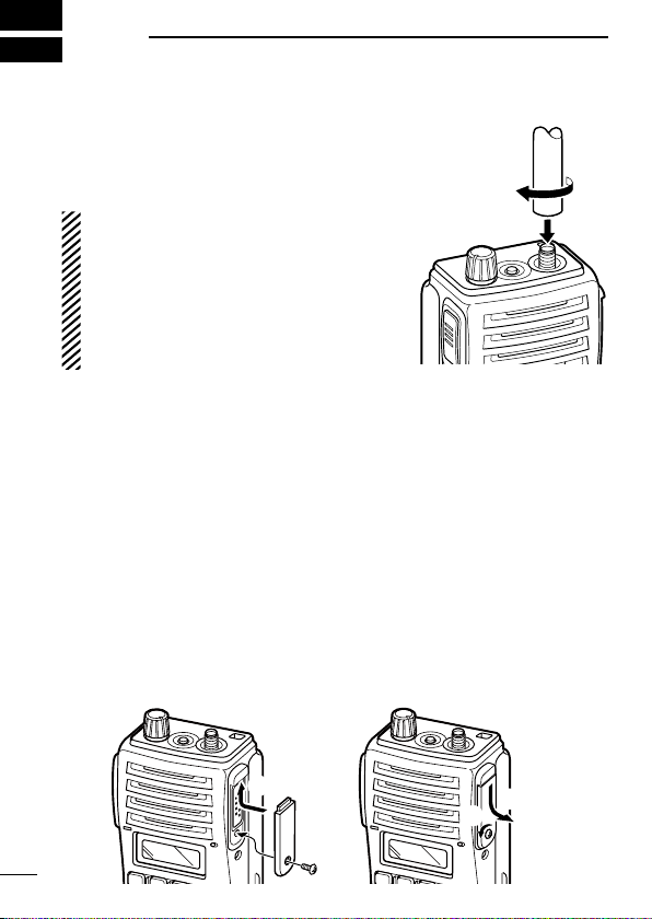
1 ACCESSORIES ......................................................................... 1–2
■Accessory attachments .............................................................. 1
2 PANEL DESCRIPTION ............................................................ 3–11
■Front, top and side panels .......................................................... 3
■Function display.......................................................................... 6
■Programmable function keys ...................................................... 7
3 CONVENTIONAL OPERATION............................................. 12–18
■Turning power ON..................................................................... 12
■Channel selection ..................................................................... 12
■Call procedure .......................................................................... 13
■Receiving and transmitting ....................................................... 14
■Scrambler function.................................................................... 17
■User Set mode.......................................................................... 18
4 BIIS OPERATION .................................................................. 19–34
■Default setting........................................................................... 19
■Receiving a call......................................................................... 20
■Transmitting a call ..................................................................... 23
■Receiving a message ............................................................... 26
■Transmitting a status ................................................................. 29
■Transmitting an SDM................................................................. 30
■Position data transmission ........................................................ 31
■Printer connection..................................................................... 32
■PC connection .......................................................................... 32

viii
SUPPLIED ACCESSORIES
The following accessories are supplied: Qty.
• Flexible antenna…………………………………………………… 1
• Battery pack ……………………………………………………… 1
• Jack cover ……………………………………………………… 1 set
• Belt clip ………………………………………………………… 1 set
• Function name stickers* (KEY-STICKER)……………………… 1
*
There are no names on the programmable function keys since the func-
tions can be freely assigned to [P0] to [P3], [Red], [ ] and [ ] keys.
Attach the supplied function name stickers above the appropriate
keys for easy recognition of that key’s assigned function.
■Digital ANI................................................................................. 32
■Auto emergency transmission .................................................. 33
■Stun function............................................................................. 33
■BIIS indication........................................................................... 34
■Priority A channel selection ...................................................... 34
5 BATTERY CHARGING .......................................................... 35–44
■Caution ..................................................................................... 35
■Optional battery chargers ......................................................... 39
6 SPEAKER-MICROPHONE .................................................... 45–46
■Optional HM-138 description .................................................... 45
■Attachment................................................................................ 46
7 OPTIONS ............................................................................... 47–48
8 ATEX CAUTIONS................................................................... 49–51
9 CE ................................................................................................ 52

1
1ACCESSORIES
■Accessory attachments
DFlexible antenna
Connect the supplied flexible antenna to
the antenna connector.
CAUTION:
• NEVER carry the transceiver by
holding the antenna.
• DO NOT connect the antenna other
than listed on page 47.
• Transmitting without an antenna
may damage the transceiver.
ïJack cover
Attach the jack cover when the optional speaker-microphone is not
used.
When the transceiver is used in a hazardous areas, either the jack
cover or HM-138 must be attached to the connector. Failure to do
this will make the transceiver ATEX non-compliant and may result
in an accident during use in hazardous areas.
To attach the jack cover:
qInsert the jack cover into the
[SP MIC] connector.
wTighten the screw.
To detach the jack cover:
qRemove the screw with a
phillips screwdriver.
wDetach the jack cover for the
speaker-microphone con-
nection.
q
w
qw

ïBattery pack
To attach the battery pack:
Slide the battery pack on the back of the transceiver in the direction
of the arrow (q), then lock it with the battery release button.
• Slide the battery pack until the battery release button makes a ‘click’
sound.
To remove the battery pack:
Push the battery release button in the direction of the arrow (w) as
shown below. The battery pack is then removed.
NEVER remove or attach the battery pack when the transceiver
is wet or soiled. This may result in water or dust getting into the
transceiver/battery pack and may damage the transceiver.
q
w
Battery pack
Batter
y release
button
DBelt clip
Attach the belt clip to the back of the transceiver with the supplied
screws.
Supplied screws
2
1
ACCESSORIES
1
2
3
4
5
6
7
8
9
10
11
12
13
14
15
16
17
18
19
20

3
2PANEL DESCRIPTION
■Front, top and side panels
q
w
e
r
t
y
i
uMicrophone
Function display
(p. 6)
Speaker
(See the following
NOTE.)
NOTE: If the speaker netting (for dust proofing) becomes
wet, dry it with a hair drier (cool mode) etc. before operating
the transceiver. Otherwise the audio may be difficult to hear
for loss of the sound pressure.

qVOLUME CONTROL [VOL]
Turns power ON and adjusts the audio level.
wRED BUTTON
The desired function can be assigned by your dealer.
eANTENNA CONNECTOR
Connects the supplied antenna.
rSPEAKER-MICROPHONE CONNECTOR [SP MIC]
Connects the optional speaker-microphone. (p. 46)
[SP MIC] jack cover
NOTE: KEEP the [SP MIC]
jack cover attached to the
transceiver when the speaker-
microphone is not used.
(See page 1 for details)
tDEALER-PROGRAMMABLE KEYS [P0] to [P3]
The desired functions can be assigned independently by your
dealer.
yCH UP AND DOWN KEYS [ ]/[ ]
➥
During standby condition, push to select an operating channel.
➥After pushing [TX Code CH Select], push to select a TX code
channel.
➥
After pushing [DTMF Autodial], push to select a DTMF channel.
➥After pushing and holding [Scan A Start/Stop]/[Scan B Start/
Stop], push to select a scan group.
➥After pushing [Digital], push to select a BIIS code, status
number or SDM.
*Desired functions can be assigned independently by your dealer.
☞Continue to the next page.
4
2
PANEL DESCRIPTION
1
2
3
4
5
6
7
8
9
10
11
12
13
14
15
16
17
18
19
20

■Front, top and side panels (Continued)
uTRANSMIT/BUSY INDICATOR
Lights red while transmitting; lights green while receiving a sig-
nal, or when the squelch is open.
iPTT SWITCH [PTT]
Push and hold to transmit; release to receive.
5
2PANEL DESCRIPTION

■Function display
ru
y
t
e
wq
i
qOUTPUT POWER INDICATOR
Appears when Low 2 or Low 1 is selected.
wAUDIBLE INDICATOR
➥Appears when the channel is in the ‘audible’ (unmute) con-
dition.
➥Appears when the specified 5-tone/BIIS code is received.
eCOMPANDER INDICATOR
Appears when the compander function is activated.
rKEY LOCK INDICATOR
Appears during the key lock function ON.
tSCRAMBLER INDICATOR
Appears when the voice scrambler function is activated.
yBELL INDICATOR
Appears/Blinks when the specific 5-tone/BIIS code is received,
according to the programming.
uBATTERY INDICATOR
Appears or blinks when the battery power decreases to a spec-
ified level.
iALPHANUMERIC DISPLAY
Displays the operating channel number, channel names, Set
mode contents, DTMF numbers, etc.
6
2
PANEL DESCRIPTION
1
2
3
4
5
6
7
8
9
10
11
12
13
14
15
16
17
18
19
20

■Programmable function keys
The following functions can be assigned to [P0], [P1], [P2], [P3],
[Red], []and [ ] programmable function keys.
Consult your Icom dealer or system operator for details concerning
your transceivers programming.
CH UP AND DOWN KEYS
• Select an operating channel.
• Select a transmit code channel after pushing the [TX Code CH
Select] keys.
• Select a DTMF channel after pushing the [DTMF Autodial] key.
• Select a scan group after pushing and holding the [Scan A Start/
Stop]/[Scan B Start/Stop] keys.
• Select a BIIS code, status number or SDM after pushing the
[Digital] key.
BANK SELECT KEY
Push this key, then push [CH Up] or [CH Down] to select the de-
sired bank.
SCAN START/STOP KEYS
➥Push this key to start scanning; and push again to stop.
➥Push and hold this key to indicate the scan group, then select
the desired scan group using [CH Up]/[CH Down].
SCAN TAG KEY
Adds or deletes the selected channel to the scan group.
7
2PANEL DESCRIPTION

PRIORITY CHANNEL KEYS
➥Push to select Priority A or Priority B channel.
➥Push and hold [Prio A (Rewrite)] to rewrite the Prio A channel.
MR-CH 1/2/3/4 KEYS
Select an operating channel directly.
MONITOR KEY
Activates one of (or two of) the following functions on each chan-
nel independently:
• Push and hold to un-mute the channel (audio is emitted; ‘Audible’ con-
dition).
• Push to mute the channel (sets to ‘Inaudible’ only).
• Push to un-mute the channel (sets to ‘Audible’ only).
• Push after the communication is finished to send a ‘reset code’.
NOTE: The un-mute condition (‘Audible’ condition) may auto-
matically return to the mute condition (‘Inaudible’ condition) after
a specified period.
LOCK KEY
Push and hold to electronically lock all programmable keys except
the following:
[Call] (incl. Call A and Call B), [Moni(Audi)] and [Emergency] keys.
OUTPUT POWER SELECTION KEY
Select the transmit output power temporarily or permanently, de-
pending on the pre-setting.
• Ask your dealer for the output power level for each selection.
☞Continue to the next page.
8
2
PANEL DESCRIPTION
1
2
3
4
5
6
7
8
9
10
11
12
13
14
15
16
17
18
19
20

■Programmable function keys (Continued)
C.TONE CHANNEL ENTER KEY
Select the continuous tone channel using [CH Up]/[CH Down] keys
to change the tone frequency/code setting after pushing this key for
permanent operation.
TALK AROUND KEY
Turn the talk around function ON and OFF.
• The talk around function equalizes the transmit frequency to the re-
ceive frequency for transceiver-to-transceiver communication.
WIDE/NARROW KEY
Push to toggle the IF bandwidth between wide and narrow.
• The wide passband width can be selected from 25.0 or 20.0 kHz using
the CS-F50 cloning software. Ask your dealer for details.
DTMF AUTODIAL KEY
➥Push to enter the DTMF channel selection mode. Then select
the desired DTMF channel using [CH Up]/[CH Down] keys.
➥After selecting the desired DTMF channel, push this key to trans-
mit the DTMF code.
DTMF RE-DIAL KEY
Push to transmit the last-transmitted DTMF code.
CALL KEYS
Push to transmit a 5-tone/BIIS ID code.
• Call transmission is necessary before you call another station depend-
ing on your signalling system.
• The [Call A] and/or [Call B] keys may be available when your system
employs selective ‘Individual/Group’ calls. Ask your dealer which call
is assigned to each key.
9
2PANEL DESCRIPTION

EMERGENCY KEYS
➥Push and hold to transmit an emergency call.
➥When [Emergency Single (Silent)] or [Emergency Repeat (Si-
lent)] is pushed, an emergency call is transmitted without a beep
emission and LCD indication change.
• If you want to cancel the emergency call, push (or push and hold)
the key again before transmitting the call.
• The emergency call is transmitted one time only or repeatedly until
receiving a control code depending on the pre-setting.
TX CODE ENTER KEY
Push to enter the direct ID code edit mode, for both 5-tone and
MSK. Then set the desired digit using [CH Up]/[CH Down]/
[TX Code CH Up]/[TX Code CH Down]. (p. 16)
TX CODE CHANNEL SELECT KEY
➥Push to enter the direct ID code channel selection mode. Then
set the desired channel using [CH Up]/[CH Down]/[TX Code CH
Up]/[TX Code CH Down]. (p. 15)
➥While in ID code channel selection mode, push for 1 sec. to enter
the ID code edit mode. Then set the desired digit using [CH Up]/
[CH Down]/[TX Code CH Up]/[TX Code CH Down]. (p. 16)
TX CODE CHANNEL UP/DOWN KEYS
Push to select a TX code channel directly.
ID MEMORY READ KEY
➥Recalls detected ID codes.
• Push this key, then push [CH Up]/[CH Down] for selection.
• Up to 5 ID’s are memorized.
➥Push and hold to erase the selected memorized ID’s.
☞Continue to the next page.
10
2
PANEL DESCRIPTION
1
2
3
4
5
6
7
8
9
10
11
12
13
14
15
16
17
18
19
20

■Programmable function keys (Continued)
VOICE SCRAMBLER FUNCTION
Push to toggle the voice scrambler function ON and OFF.
COMPANDER KEY
Push to toggle the compander function ON and OFF.
The compander function reduces noise components from the trans-
mitting audio to provide clear communication.
USER SET MODE KEY
➥Push and hold to enter the User Set mode.
• During the User Set mode, push this key to select an item that is
enabled by your dealer, and push [CH Up]/[CH Down] to change
the value or condition.
➥Push and hold this key again to exit the User Set mode.
DIGITAL KEY (BIIS operation only)
➥Push to select the call ID list, transmit message and standby
condition. Toggles between queue channel and received mes-
sage record indication after queue channel is selected.
➥Push and hold to select queue channel indication.
STATUS UP/DOWN KEYS (BIIS operation only)
➥While in the standby condition, push to display the transmit sta-
tus indication and select a status number.
➥When a received SDM is displayed, push to cancel the auto-
matic scroll and scroll the message manually.
➥When an SDM that contains more than 8 characters is dis-
played, push to scroll the message manually.
11
2PANEL DESCRIPTION
Other manuals for IC-F61-L
1
This manual suits for next models
2
Table of contents
Other Icom Transceiver manuals

Icom
Icom IC-F11/Sl IC-F21/S User manual

Icom
Icom IC-505 User manual

Icom
Icom IC-208H User manual

Icom
Icom ID-31E PLUS Installation guide

Icom
Icom IC-730 User manual

Icom
Icom IC-M506 User manual

Icom
Icom IC-M401EURO User manual

Icom
Icom IC-2SAT User manual

Icom
Icom IC-280 User manual

Icom
Icom IC-M87 User manual