PANEL DESCRIPTION
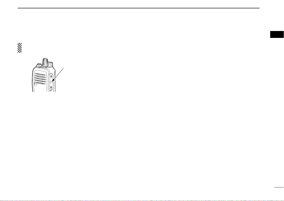
16
15
14
13
12
11
10
9
8
7
6
4
5
3
2
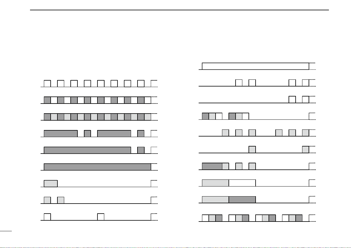
TX Low BATT2
Clone Err
Clone TX/RX
Low BATT1
Low BATT2
Busy
F/S Scan
Call LED Blink
Call LED ON
TX Low BATT1
Clone
G GGGG GGG
R G R G R G R G R G R G R G R G
R O R O R O R O R O R O R O R O
R R R R
R R
R
O
OO
G G
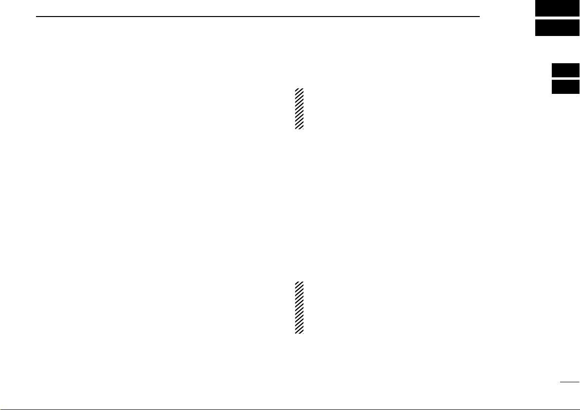
TX Low BATT2
Clone Err
Clone TX/RX
Low BATT1
Low BATT2
Busy
F/S Scan
Call LED Blink
Call LED ON
TX Low BATT1
Clone
G G
R O G R O G
OOOOOO
OOOO
OOOR
O G
O R
OOOOGR RGGRGR
G G G G
G
■Programmable function keys
The following functions can be assigned to [Emer], [Upper],
[Lower], and [Ext. Emer].
Consult your Icom dealer or system operator for details con-
cerning your transceiver’s programming.
SCAN START/STOP
➥Push to start and cancel a scan.
•
When a scan is started with the Power ON Scan or Auto-
matic scan function, push this key to cancel it. The can-
celled scan resumes after a set time period.
PRIORITY A CHANNEL, PRIORITY B CHANNEL
➥Push to select the Priority A or Priority B channel.
PRIORITY A CHANNEL (REWRITE),
PRIORITY B CHANNEL (REWRITE)
➥Push to select the Priority A or Priority B channel.
➥Hold down [Prio A (Rewrite)] or [Prio B (Rewrite)] to assign
the operating channel to Priority A or Priority B channel,
respectively.
MEMORY CHANNELS 1, 2, 3, 4
➥Push to directly select memory channel 1, 2, 3 or 4, if pro-
grammed.
MONI
➥Hold down to cancel the CTCSS (DTCS) or 2-Tone mute.
The transceiver enters “Audible” mode.
➥Push to turn OFF the function.
LOCK
➥Hold down this key to lock all programmable keys except
the followings:
[Moni], [Lock], [Emer], [Surveillance], [Siren], [Lone
Worker], and [Shift].
LONE WORKER
➥Hold down to turn ON the Lone Worker
Function. ➥Push to turn OFF the Function.
HIGH/LOW
➥Push to select the transmit output power temporarily or
permanently, depending on the presetting.