Icom IC-7200 User manual

INSTRUCTION MANUAL
HF/50 MHz TRANSCEIVER
i7200

IMPORTANT
READ THIS INSTRUCTION MANUAL
CAREFULLY before attempting to operate the
transceiver.
SAVE THIS INSTRUCTION MANUAL. This
manual contains important safety and operating in-
structions for the IC-7200.
FOREWORD
We understand that you have a choice of many differ-
ent radios in the market place. We want to take a cou-
ple of moments of your time to thank you for making
the IC-7200 your radio of choice, and hope you agree
with Icom’s philosophy of “technology first.” Many
hours of research and development went into the de-
sign of your IC-7200.
D
FEATURES
❍IF DSP features
❍Digital Twin PBT
❍Manual notch function
❍±0.5 ppm of high frequency stability
❍Simple operation
❍Tough and compact body
❍Standard voice synthesizer
EXPLICIT DEFINITIONS
WORD DEFINITION
RWARNING Personal injury, fire hazard or electric
shock may occur.
CAUTION Equipment damage may occur.
NOTE
If disregarded, inconvenience only. No risk
of personal injury, fire or electric shock.
SUPPLIED ACCESSORIES
The transceiver comes with the following accessories.
Qty.
q Hand microphone (HM-36) ............................. 1
w DC power cable (OPC-1457) .......................... 1
e Spare fuse (ATC 5 A) ...................................... 1
r Spare fuse (ATC 30 A) .................................... 2
tACC cable ......................................................... 1
y3.5 (d) mm plug................................................. 1
u6.3 (d) mm Electronic keyer plug ...................... 1
iMicrophone hanger........................................... 1
oJack cap (for [PHONES]) ................................. 1
q
e
t
w
y u
r
i o
FCC INFORMATION
• FOR CLASS B UNINTENTIONAL RADIATORS:
This equipment has been tested and found to comply
with the limits for a Class B digital device, pursuant to
part 15 of the FCC Rules. These limits are designed
to provide reasonable protection against harmful in-
terference in a residential installation. This equipment
generates, uses and can radiate radio frequency en-
ergy and, if not installed and used in accordance with
the instructions, may cause harmful interference to
radio communications. However, there is no guaran-
tee that interference will not occur in a particular in-
stallation. If this equipment does cause harmful inter-
ference to radio or television reception, which can be
determined by turning the equipment off and on, the
user is encouraged to try to correct the interference
by one or more of the following measures:
• Reorient or relocate the receiving antenna.
• Increase the separation between the equipment
and receiver.
• Connect the equipment into an outlet on a circuit
different from that to which the receiver is con-
nected.
• Consult the dealer or an experienced radio/TV
technician for help.
Icom, Icom Inc. and the logo are registered trademarks of
Icom Incorporated (Japan) in the United States, the United King-
dom, Germany, France, Spain, Russia and/or other countries.
Microsoft, Windows and Windows Vista are either registered trade-
marks or trademarks of Microsoft Corporation in the United States
and/or other countries.
All other products or brands are registered trademarks or trade-
marks of their respective holders.
i

PRECAUTIONS
RWARNING RF EXPOSURE! This device emits
Radio Frequency (RF) energy. Extreme caution
should be observed when operating this device. If
you have any questions regarding RF exposure and
safety standards please refer to the Federal Com-
munications Commission Office of Engineering and
Technology’s report on Evaluating Compliance with
FCC Guidelines for Human Radio Frequency Electro-
magnetic Fields (OET Bulletin 65).
RWARNING HIGH VOLTAGE! NEVER touch an
antenna or internal antenna connector during trans-
mission. This may result in an electrical shock or burn.
RWARNING! NEVER operate the transceiver
while driving a vehicle. Safe driving requires your full
attention—anything less may result in an accident.
RNEVER apply AC power to the [DC13.8V] socket
on the transceiver rear panel. This could cause a fire
or damage the transceiver.
RNEVER apply more than 16 V DC, such as a 24 V
battery, to the [DC13.8V] socket on the transceiver
rear panel. This could cause a fire or damage the
transceiver.
RNEVER let metal, wire or other objects touch any
internal part or connectors on the rear panel of the
transceiver. This may result in an electric shock or this
could cause a fire or damege the transceiver.
RNEVER expose the transceiver to rain, snow or
any liquids.
DO NOT use or place the transceiver in areas with
temperatures below –10°C (+14°F) or above +60°C
(+140°F). Be aware that temperatures on a vehicle’s
dashboard can exceed +80°C (+176°F), resulting in
permanent damage to the transceiver if left there for
extended periods.
DO NOT place the transceiver in excessively dusty
environments or in direct sunlight.
DO NOT place the transceiver against walls or put
anything on top of the transceiver. This will obstruct
heat dissipation.
Place unit in a secure place to avoid inadvertent use
by children.
During mobile operation, NEVER place the trans-
ceiver where air bag deployment may be obstructed.
During mobile operation, DO NOT place the trans-
ceiver where hot or cold air blows directly onto it.
During mobile operation, DO NOT operate the trans-
ceiver without running the vehicle’s engine. When the
transceiver’s power is ON and your vehicle’s engine
is OFF, the vehicle’s battery will quickly become ex-
hausted.
Make sure the transceiver power is OFF before start-
ing the vehicle engine. This will avoid possible dam-
age to the transceiver by ignition voltage spikes.
During maritime mobile operation, keep the trans-
ceiver and microphone as far away as possible from
the magnetic navigation compass to prevent errone-
ous indications.
BE CAREFUL! The rear panel will become hot when
operating the transceiver continuously for long peri-
ods.
BE CAREFUL! If a linear amplifier is connected, set
the transceiver’s RF output power to less than the
linear amplifier’s maximum input level, otherwise, the
linear amplifier will be damaged.
Use Icom microphones only (supplied or optional).
Other manufacturer’s microphones have different pin
assignments, and connection to the IC-7200 may
damage the transceiver.
For U.S.A. only
Caution: Changes or modifications to this trans-
ceiver, not expressly approved by Icom Inc., could
void your authority to operate this transceiver under
FCC regulations.
ii

iii
TABLE OF CONTENTS
IMPORTANT............................................................... i
FOREWORD .............................................................. i
EXPLICIT DEFINITIONS............................................ i
SUPPLIED ACCESSORIES....................................... i
FCC INFORMATION .................................................. i
PRECAUTIONS......................................................... ii
TABLE OF CONTENTS ....................................... iii-iv
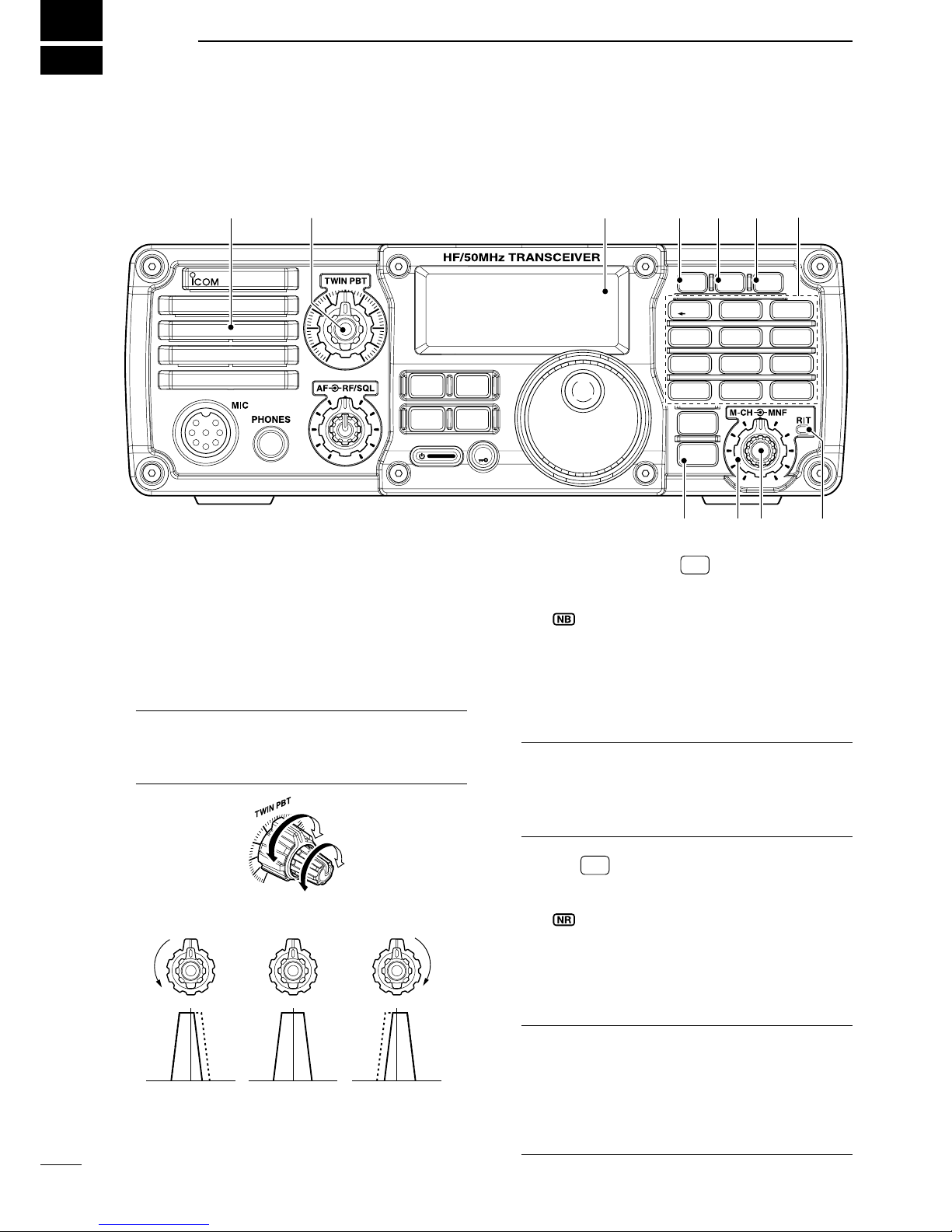
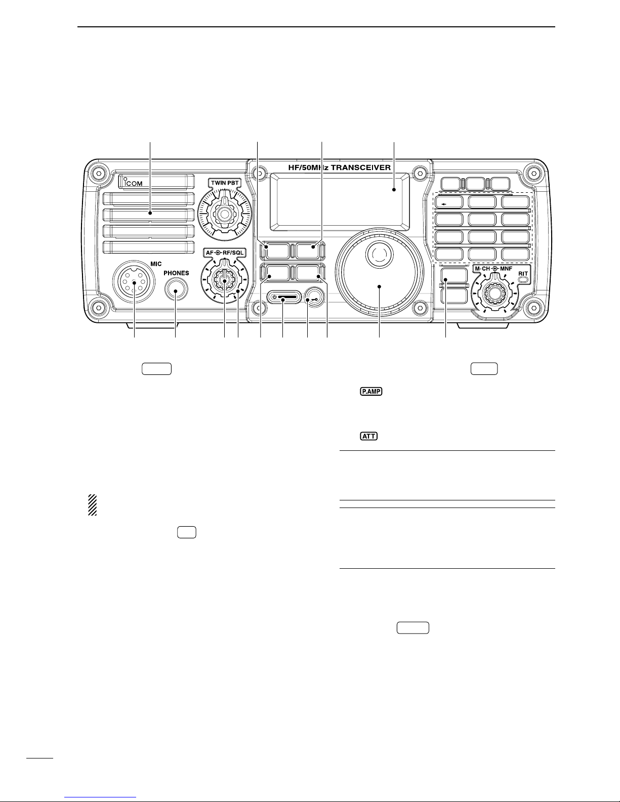
1 PANEL DESCRIPTION................................... 1–11
■
Front panel ........................................................ 1
D Keypad .......................................................... 5
■
Function display ................................................ 7
■
Rear panel......................................................... 9
D ACC socket information .............................. 10
■
Microphones.................................................... 11
D HM-36 ......................................................... 11
D SM-20 ......................................................... 11
2 INSTALLATION AND CONNECTIONS........ 12–20
■
Unpacking ....................................................... 12
■
Selecting a location ......................................... 12
■
Grounding ....................................................... 12
■
Antenna connection ........................................ 12
■
Required connections...................................... 13
■
Advanced connections .................................... 14
■
Power supply connections............................... 15
■
Connecting the DC Power Supply................... 15
■
Battery connections......................................... 15
■
External antenna tuners .................................. 16
■
Linear amplifier connections............................ 17
■Connections for CW ........................................ 18
■Connections for RTTY..................................... 19
D Connections for RTTY (FSK) ...................... 19
D Connections for RTTY (AFSK).................... 19
■Connections for SSTV or PSK31 .................... 20
D When connecting to the [ACC] socket......... 20
D When connecting to the [MIC] connector.... 20
D When connecting to the [USB] jack............. 20
3 BASIC OPERATION..................................... 21–32
■ Before first applying power.............................. 21
■ Applying power (CPU resetting)...................... 21
■ VFO description............................................... 22
■ VFO operation ................................................. 22
D Selecting the VFO A/B ................................ 22
D VFO equalization......................................... 22
■ Selecting VFO/memory mode ......................... 23
D Differences between VFO mode and
memory mode............................................. 23
■ Selecting an operating band ........................... 24
D Using the band stacking register................. 24
■ Frequency setting............................................ 25
D Using the main dial ..................................... 25
D Direct frequency entry with keypad............. 25
D Programmable tuning steps ........................ 26
D Selecting the programmable tuning step..... 26
D 1 Hz and 10 Hz tuning steps....................... 27
D TS switch flow chart ................................. 27
D Auto tuning step function ............................ 28
D ¼ tuning function
(SSB data/CW/RTTY only) ......................... 28
D Band edge warning beep............................ 28
■ Volume setting................................................. 29
■ Operating mode selection ............................... 29
■ Dial lock function ............................................. 29
■ RF gain and Squelch....................................... 30
■ Meter function ................................................. 30
■ Basic transmit operation.................................. 31
D Transmitting................................................. 31
D
Output power and Microphone gain settings
... 31
■ Voice synthesizer function............................... 32
4 RECEIVE AND TRANSMIT .......................... 33–43
■ Operating SSB ................................................ 33
D Convenient functions for receive................. 33
D Convenient functions for transmit................ 34
D About 5 MHz band operation
(USA version only) ...................................... 34
■ Operating CW ................................................. 35
D Convenient functions for receive................. 36
D Convenient functions for transmit................ 36
D CW reverse mode ....................................... 37
D CW pitch control.......................................... 37
D CW side tone function................................. 38
D Keying speed setting................................... 38
■Operating RTTY (FSK).................................... 39
D Convenient functions for receive................. 39
D RTTY reverse mode.................................... 40
D Twin peak filter ............................................ 40
D RTTY decode set mode .............................. 41
■ Operating AM .................................................. 42
D Convenient functions for receive................. 42
D Convenient functions for transmit................ 42
■ Data mode (SSTV/PSK31) operation.............. 43

TABLE OF CONTENTS
5 FUNCTIONS FOR RECEIVE........................ 44–52
■ RIT function..................................................... 44
■ Preamp and attenuator ................................... 45
■ AGC function................................................... 45
D AGC time constant selection....................... 45
■ Twin PBT operation ......................................... 46
■ IF filter selection .............................................. 47
D IF filter selection.......................................... 47
D FIlter passband width setting ...................... 48
D IF fIlter shape (SSB/CW only)..................... 48
■ Noise blanker .................................................. 49
D Noise blanker settings................................. 49
■ Noise reduction ............................................... 50
D Noise reduction level setting ....................... 50
■ Notch function ................................................. 51
D Auto notch function ..................................... 51
D Manual notch function................................. 51
D Manual notch filter setting ........................... 52
6 FUNCTIONS FOR TRANSMIT ..................... 53–60
■ VOX function.................................................... 53
D Adjusting the VOX function.......................... 53
D VOX set mode ............................................. 54
■ Break-in function ............................................. 55
D Semi break-in operation.............................. 55
D Full break-in operation ................................ 56
■ Speech compressor ........................................ 57
D Compression level setting ........................... 57
■ Split frequency operation ................................ 58
D Quick split function...................................... 59
D Split lock function ........................................ 59
■Measuring SWR .............................................. 60
7 MEMORY OPERATION................................ 61–64
■Memory channels............................................ 61
■Memory channel selection .............................. 61
■Memory programming ..................................... 62
D Programming in VFO mode ........................ 62
D Programming in memory mode................... 62
■Frequency copying .......................................... 63
D Copying in memory mode........................... 63
■Memory clearing ............................................. 64
8 SCAN OPERATION...................................... 65–66
■ Scan types ...................................................... 65
■ Preparation...................................................... 65
■ Programmed scan operation (VFO mode) ...... 66
■ Memory scan operation (Memory mode) ........ 66
9 ANTENNA TUNER OPERATION ................. 67–69
■ Optional AT-180 automatic antenna tuner
operation ......................................................... 67
D Tuner operation ........................................... 67
D Manual tuning ............................................. 67
■ AT-180 internal switch description ................... 68
■ Optional AH-4 automatic antenna tuner
operation ......................................................... 69
D AH-4 operation............................................ 69
10 SET MODE ................................................... 70–82
■ General ........................................................... 70
D Quick set mode operation ........................... 70
D Set mode operation..................................... 70
■ Quick set mode ............................................... 71
■ Set mode......................................................... 74
D Paddle operation from [MIC] connector ...... 82
11 MAINTENANCE ........................................... 83–84
■ Fuse replacement ........................................... 83
D DC power cable fuse replacement .............. 83
D Circuitry fuse replacement .......................... 83
■ Memory backup............................................... 84
■ Resetting the CPU .......................................... 84
■ Cleaning .......................................................... 84
12 TROUBLESHOOTING.................................. 85–86
13 OPTION INSTALLATIONS ................................. 87
■ MB-116 handles installation ........................... 87
■ MB-117 carrying handle installation............. 87
■
MB-118 mobile mounting bracket installation
.. 87
14 CONTROL COMMAND ................................ 88–91
■ Remote jack (CI-V) information ....................... 88
D CI-V connection example............................ 88
D Data format ................................................. 88
D Command table........................................... 89
D Band stacking register ................................ 91
D Data mode with filter width setting .............. 91
15 SPECIFICATIONS .............................................. 92
■ General ........................................................... 92
■ Transmitter....................................................... 92
■ Receiver .......................................................... 92
16 OPTIONS...................................................... 93–94
17 ABOUT CE ................................................... 95–96
18 BAND VOLTAGE MODIFICATION...................... 97
■ Band voltage modification ............................... 97
iv
1
2
3
4
5
6
7
8
9
10
11
12
13
14
15
16
17
18
19
20
21

qPASSBAND TUNING CONTROLS [TWIN PBT]
Adjust the receiver’s DSP filter passband width.
(p. 46)
• The limit of the variable range depends on the pass-
band width and mode. The limit of the variable range
is half of the passband width, and PBT is adjustable in
200 Hz (AM) or 50 Hz (other models) steps.
• Rotate both [TWIN PBT] controls (PBT1 and PBT2) to
the same position shifts the IF.
4What is the PBT control?
Generally, the PBT electronically narrows the IF
passband width to reject interference. This trans-
ceiver uses the DSP circuit for the PBT function.
PBT2
PBT1
Low cutHigh cut Center
TWIN PBT TWIN PBT TWIN PBT
–+
wNOISE BLANKER KEY NB (p. 49)
➥Push to turn the noise blanker function ON or
OFF.
• “ ” appears on the display.
➥Push and hold for 1 sec to enter the noise
blanker set mode for setting the noise blanker
level and blank time
; push again to return to nor-
mal operation.
• When entering the noise blanker set mode, the noise
blanker function is automatically turned ON.
4What is the noise blanker?
The noise blanker reduces pulse-type noise such
as that generated by automobile ignition systems.
This function is not effective against non pulse-type
noise.
eNR KEY NR (p. 50)
➥Push to turn the noise reduction function ON or
OFF.
• “ ” appears on the display.
➥Push and hold for 1 sec. to enter the noise re-
duction level set mode
; push again to return to
normal operation.
• When entering the noise reduction set mode, the
noise reduction function is automatically turned ON.
4What is the Noise Reduction function?
The Noise Reduction (NR) function removes ran-
dom noise from the receiver passband. The level is
adjustable to allow maximum clarity without harm-
ing the intelligibility of the desired signal. Noise Re-
duction should generally not be used with digital
modes.
1
1
PANEL DESCRIPTION
i7200
MODE
TUNER
TS
FILTER
SPCH
V/M
A/B
SPLIT
M-CL
SCAN
SET
ATT
P
.
AMP
COMP
VOX
MNF
RIT
12 3
4 5 6
78
0
50
28
1814
10
21 24
=
7
3.5
1.8
F-INP
M-CH/RIT
ENT
BAND
GENE
9
.
AGC
MW
ANF
METER
NRNB
Speaker trew
Function
Display (p. 7)
ui y
q
o
■
Front panel

2
rANF/METER KEY ANF
METER (p. 51)
➥
Push to turn the Automatic Notch Filter function
ON or OFF in SSB and AM modes.
• “ ” appears on the display.
➥Push and hold for 1 sec. to toggle the meter
function; (pgs. 30, 60)
PO ➟SWR ➟ALC
• PO : indicates the relative RF output power.
• SWR : indicates the SWR over the transmission line.
• ALC : Indicates ALC level.
4What is the Automatic Notch Filter?
The Automatic Notch Filter is a narrow DSP filter that
automatically identifies and attenuates beat tones, tun-
ing signals, CW, etc., even if they are moving and re-
moves them from the receiver passband while pre-
serving the desired signal’s frequency response.
tKEYPAD
➥ V/M
➔
,
A/B
=
,
SPLIT
,
MW
,
M-CL
,
AGC
,
COMP
,
SCAN
,
VOX
,
RIT
and
MNF
keys are available.
(p. 5)
➥After pushing and holding F-INP ENT
BAND for 1 sec.,
push a key on the keypad to select the operating
band. (p. 24)
• The band stacking register is available.
• •
GENE selects the general coverage band.
➥After pushing F-INP ENT
BAND , push a key on the key-
pad to enter a numeric frequency. After entering,
push F-INP ENT
BAND . (p. 25)
• e.g. To enter 14.195 MHz;
Push F-INP ENT
BAND , 1
1.8 , 4
10 , •
GENE , 1
1.8 , 9
28 , 5
14
and F-INP ENT
BAND .
yRIT CONTROL INDICATOR (pgs. 44, 61)
Lights orange when [M-CH] control (u) acts as the
RIT control.
uM-CH/RIT CONTROL [M-CH] (inner control)
➥While in the set mode/quick set mode, rotate to
select the set mode item. (p. 70)
➥This control can act as the memory channel
control or RIT control.
• The RIT function should be turned ON in advance to
activate this control as RIT control. (p. 44)
- “ ” appears when the RIT function is turned ON.
• The RIT control indicator (y) lights orange when
this control is activated as the RIT control.
During [M-CH] acts as the M-CH control:
Rotate to select a memory channel (p. 61).
OFF
M-CH
Channel decreases
Channel increases
During [M-CH] acts as RIT control:
Rotate to shift the receive frequency (p. 44).
• Rotate the control clockwise to incerase the fre-
quency, or rotate the control counterclockwise to de-
crease the frequency.
• The shift frequency range is ±9.999 kHz in 1 Hz
steps (or ±9.99 kHz in 10 Hz steps).
Lights orange
RIT
Frequency decreases
Frequency increases
4What is the RIT function?
The RIT (Receiver Incremental Tuning) shifts the re-
ceive frequency without shifting the transmit frequency.
This is useful for fine tuning for stations calling you
off-frequency or when you prefer to listen to slightly
different sounding voice characteristics, etc.
• About the [M-CH] control activation:
RIT control indicator (yon p. 2)
Lights OFF
indicator
(!6 on p. 8)
Appears Acts as the
RIT control Acts as the mem-
ory channel control
Disappears N/A
iMANUAL NOTCH FILTER CONTROL [MNF]
(outer control; p. 51)
Rotate to adjust the notch filter frequency to reject
an interfering signal while the manual notch func-
tion is ON.
• The filter width can be set to narrow, middle or wide in
the manual notch filter set mode.
High frequency
Low frequency
4What is the Manual Notch Filter?
The Manual Notch Filter is an adjustable narrow
DSP filter that removes tones from CW, SSB, AM
or RTTY signals while preserving the desired sig-
nal’s frequency response.
oM-CH/RIT•SET KEY M-CH/RIT
SET
➥Push to toggle the [M-CH] control activation be-
tween memory channel control and RIT control.
•
The RIT function should be turned ON in advance. (p. 44)
• The RIT control indicator (y) lights orange when the
[M-CH] control functions as the RIT control.
➥Push and hold for 1 sec. to enter the quick set
mode. (p. 70)
➥During quick set mode, push and hold for 1 sec.
to enter the set mode (p. 70)
➥During quick set mode or set mode, push to re-
turn to normal operation. (p. 70)
1
PANEL DESCRIPTION
1
2
3
4
5
6
7
8
9
10
11
12
13
14
15
16
17
18
19
20
21

3
!0 MODE KEY MODE (p. 29)
➥Push momentarily to cycle through the operating
modes:
USB/LSB ➟CW/CW-R ➟RTTY/RTTY-R ➟AM
➥Push and hold for 1 sec. to toggle the following
operating modes:
USB ↔LSB (p. 33)
CW ↔CW-R (Reverse) (p. 35)
RTTY ↔RTTY-R (Reverse) (p. 39)
• “CW-R” or “RTTY-R” appears on the display when
reverse mode is selected.
Undesired modes can be inhibited in set mode.
(p. 81)
!1 TUNING STEP KEY TS (pgs. 26, 27)
➥Push to turn the programmable tuning step ON
or OFF.
• “√” appears above the 1 kHz indicator when the pro-
grammable tuning step is turned ON and the fre-
quency can be changed in programmed kHz steps.
➥
While the
programmable
tuning step is turned
ON (
“√” appears
), push and hold for 1 sec. to
enter tuning step set mode; push again to return
to normal operation.
• 0.1, 1, 5, 9 and 10 kHz programmable tuning steps
are available.
➥
While the
programmable
tuning step is turned
OFF, push and hold for 1 sec. to turn the 1 Hz
step ON and OFF.
• 1 Hz indication appears, and the frequency can be
changed in 1 Hz steps.
!2 PREAMP/ATTENUATOR KEY P.AMP
ATT (p. 45)
➥Push to turn the preamp ON or OFF.
• “ ” appears on the display.
➥Push and hold for 1 sec. to turn the 20 dB atten-
uator ON; push momentarily to turn the attenua-
tor OFF.
• “ ” appears on the display.
4What is the preamp?
The preamp amplifies signals in the receiver front
end (input) circuit to improve the sensitivity. Turn
the preamp ON when receiving weak signals.
4What is the attenuator?
The attenuator prevents a strong undesired signal
near the desired frequency or near your location,
such as from a broadcast station, from causing dis-
tortion or spurious signals.
!3 MAIN DIAL [DIAL]
Changes the displayed frequency and selects val-
ues for selected set mode items, etc.
!4 FILTER KEY FILTER (p. 47)
➥Push momentarily to cycle the IF filter settings
between wide, middle and narrow for the se-
lected operating mode.
➥Push and hold for 1 sec. to enter the filter set
mode.
i7200
MODE
TUNER
TS
FILTER
SPCH
V/M
A/B
SPLIT
M-CL
SCAN
SET
ATT
P
.
AMP
COMP
VOX
MNF
RIT
12 3
4 5 6
78
0
50
28
1814
10
21 24
=
7
3.5
1.8
F-INP
M-CH/RIT
ENT
BAND
GENE
9
.
AGC
MW
ANF
METER
NRNB
Speaker
Function
Display (p. 7)
!3@1 !5 !4!6!7!9 !8@0
!1!0
!2
■
Front panel (Continued)
1PANEL DESCRIPTION

4
1
PANEL DESCRIPTION
1
2
3
4
5
6
7
8
9
10
11
12
13
14
15
16
17
18
19
20
21
!5 SPCH•LOCK KEY
SPCH
➥Push to announce the selected frequency and
S-meter level by the speech synthesizer. (p. 32)
• The parameters to be announced can be selected in
the set mode. (p. 77)
➥Push and hold for 1 sec. to turn the dial lock
function ON or OFF. (p. 29)
• The dial lock function electronically locks the main
dial.
• “ ” appears while the dial lock function is ON.
!6 POWER KEY
➥Push to turn power ON.
• Turn the DC power supply ON in advance.
➥Push and hold for 1 sec. to turn power OFF.
!7 TUNER KEY TUNER (p. 67)
➥Push to turn the automatic antenna tuner func-
tion ON or OFF.
• An optional antenna tuner must be connected.
• “ ” appears on the display.
➥Push and hold for 1 sec. to manually tune the
antenna tuner.
• An optional antenna tuner must be connected.
• When the tuner cannot tune the antenna, the tuning
circuit is bypassed automatically after 20 sec.
!8 RF GAIN/SQUELCH CONTROL [RF/SQL]
(outer control; p. 30)
➥Adjusts the RF gain and squelch threshold level.
➥
The squelch removes noise output from the
speaker (closed condition) when no signal is re-
ceived.
• The squelch is available for all modes.
• The control can be set as the squelch plus RF gain
controls, squelch control only (RF gain is fixed at
maximum) or Auto (RF gain control in SSB, CW and
RTTY; squelch control in AM) in set mode.
MODE SET MODE SETTING
AUTO SQL RF + SQL
SSB, CW
RTTY RF GAIN SQL RF GAIN + SQL
AM SQL SQL RF GAIN + SQL
Minimum RF gain
Adjustable range
RF gain adjustable
range
Maximum RF gain
Maximum RF gain
Squelch is open. S-meter squelch
S-meter squelch
threshold
Lowest threshold Highest threshold
Squelch is open.
S-meter squelch
S-meter squelch
threshold
• When functioning as RF GAIN/SQL control
• When functioning as RF GAIN control
(Squelch is fixed open; SSB, CW, RTTY only)
• When functioning as SQL control
(RF gain is fixed at maximum.)
!9 AF CONTROL [AF] (inner control; p. 29)
Varies the audio output level from the speaker.
Audio output
decreases
Audio output
increases
@0 HEADPHONE JACK [PHONES]
Accepts headphones with 8–16 Ωimpedance.
• Output power: 5 mW with an 8 Ωload.
• When headphones are connected, no receive audio
comes from the speaker.
@1 MICROPHONE CONNECTOR [MIC]
Accepts supplied or optional microphone.
• See p. 11 for appropriate microphones and microphone
connector information.

5
1PANEL DESCRIPTION
@2 VFO/MEMORY/1/1.8 MHz BAND KEY
V/M
➔
➥Push to toggle the operating mode be-
tween VFO mode or memory mode.
(pgs. 23, 61)
➥Push and hold for 1 sec. to copy the
memory contents to VFO. (p. 63)
1
1.8 ➥Push F-INP ENT
BAND , then push this key to in-
put the number ‘1.’ (p. 25)
➥Push and hold F-INP ENT
BAND for 1 sec., then
push this key to select the 1.8 MHz band.
(p. 24)
@3
VFO SELECT/EQUALIZATION/2/3.5 MHz BAND KEY
A/B
=
➥Push to toggle between VFO A and
VFO B. (p. 22)
➥Push and hold for 1 sec. to equalize the
frequency and operating mode of the two
VFO’s. (p. 22)
• The undisplayed VFO frequency and operat-
ing mode are set the same as the displayed
VFO frequency and operating mode.
2
3.5 ➥Push F-INP ENT
BAND , then push this key to in-
put the number ‘2.’ (p. 25)
➥Push and hold F-INP ENT
BAND for 1 sec., then
push this key to select the 3.5 MHz band.
(p. 24)
@4 SPLIT/3/7 MHz BAND KEY
SPLIT ➥Push to toggle the split function ON and
OFF. (p. 58)
• “ ” appears on the display.
➥Push and hold for 1 sec. to activate the
quick split function. (p. 59)
• The VFO B frequency and operating mode
are set the same as the VFO A frequency
and operating mode.
• The quick split function can be turned OFF
in the set mode. (p. 76)
3
7➥Push F-INP ENT
BAND , then push this key to in-
put the number ‘3.’ (p. 25)
➥Push and hold F-INP ENT
BAND for 1 sec., then
push this key to select the 7 MHz band.
(p. 24)
@5 MEMORY WRITE/4/10 MHz BAND KEY
MW Push and hold for 1 sec. to store the dis-
played VFO frequency and operating mode
into the selected memory channel. (p. 62)
4
10 ➥Push F-INP ENT
BAND , then push this key to in-
put the number ‘4.’ (p. 25)
➥Push and hold F-INP ENT
BAND for 1 sec., then
push this key to select the 10 MHz band.
(p. 24)
i7200
MODE
TUNER
TS
FILTER
SPCH
V/M
A/B
SPLIT
M-CL
SCAN
SET
ATT
P
.
AMP
COMP
VOX
MNF
RIT
12 3
4 5 6
78
0
50
28
1814
10
21 24
=
7
3.5
1.8
F-INP
M-CH/RIT
ENT
BAND
GENE
9
.
AGC
MW
ANF
METER
NRNB
V/M
A/B
SPLIT
M-CL
SCANCOMP
VOX
MNF
RIT
12 3
4 5 6
78
0
50
28
1814
10
21 24
=
7
3.5
1.8
F-INP ENT
BAND
GENE
9
.
AGC
MW
@9
@4@3@2
#0
#3
@6
@7
#2 #1
@8
@5
DKeypad

6
1
PANEL DESCRIPTION
1
2
3
4
5
6
7
8
9
10
11
12
13
14
15
16
17
18
19
20
21
@6 MEMORY CLEAR/5/14 MHz BAND KEY
M-CL ➥Push and hold for 1 sec. to clear the
displayed memory channel contents in
memory mode. (p. 64)
• “ ” appears above the memory chan-
nel number.
➥Push and hold for 1 sec., to select a
default condition or value when in set
mode/quick set mode. (p. 70)
5
14 ➥Push F-INP ENT
BAND , then push this key to in-
put the number ‘5.’ (p. 25)
➥Push and hold F-INP ENT
BAND for 1 sec., then
push this key to select the 14 MHz band.
(p. 24)
@7 AGC/6/18 MHz BAND KEY
AGC ➥Push to toggle the time constant for
the AGC circuit fast and slow. (p. 45)
• “F.AGC” appears on the display when
fast AGC is selected; no indication ap-
pears when slow AGC is selected
➥Push and hold for 1 sec. to turn the
AGC function OFF.
• “AGC-OFF” appears on the display.
6
18 ➥Push F-INP ENT
BAND , then push this key to
input the number ‘6.’ (p. 25)
➥Push and hold F-INP ENT
BAND for 1 sec.,
then push this key to select the 18
MHz band. (p. 24)
@8 SPEECH COMPRESSOR/7/21 MHz BAND KEY
COMP ➥Push to turn the speech compressor
function ON or OFF. (p. 57)
• “ ” appears on the display.
➥Push and hold for 1 sec. to enter the
speech compression level set mode;
push again to return to normal operation.
7
21 ➥Push F-INP ENT
BAND , then push this key to in-
put the number ‘7.’ (p. 25)
➥Push and hold F-INP ENT
BAND for 1 sec., then
push this key to select the 21 MHz band.
(p. 24)
@9 SCAN/8/24 MHz BAND KEY
SCAN Push to start/stop the programmed/
memory scan in VFO/memory mode.
(p. 66)
• “ ” appears on the display during
scanning.
8
24 ➥Push F-INP ENT
BAND , then push this key to
input the number ‘8.’ (p. 25)
➥Push and hold F-INP ENT
BAND for 1 sec.,
then push this key to select the 24
MHz band. (p. 24)
#0 VOX/9/28 MHz BAND KEY
VOX ➥Push to turn the VOX function ON or
OFF. (p. 53)
➥Push and hold for 1 sec. to enter VOX
set mode; push again to return to nor-
mal operation.
9
28 ➥Push F-INP ENT
BAND , then push this key to
input the number ‘9.’ (p. 25)
➥Push and hold F-INP ENT
BAND for 1 sec.,
then push this key to select the 28
MHz band. (p. 24)
4What is the VOX function?
The VOX function (Voice-Operated Transmission)
activates the transmitter when you speak into the
microphone and automatically returns to receive
when you stop speaking.
#1 MANUAL NOTCH FILTER/0/50 MHz BAND KEY
MNF ➥Push to turn the manual notch filter func-
tion ON or OFF. (p. 51)
• “ ” appears on the display.
➥Push and hold for 1 sec. to enter the
manual notch set mode; push again to
return to normal operation. (p. 52)
• Before entering the set mode, the manual
notch filter function is turned ON.
0
50 ➥Push F-INP ENT
BAND , then push this key to in-
put the number ‘0.’ (p. 25)
➥Push and hold F-INP ENT
BAND for 1 sec., then
push this key to select the 50 MHz band.
(p. 24)
#2 RIT/•/GENERAL BAND KEY
RIT ➥
Push to turn the RIT (Receiver Incremen-
tal Tuning) function ON or OFF. (p. 44)
• “ ” appears on the display.
• RIT frequency can be adjusted with [M-CH]
control when RIT mode is selected.
➥Push and hold for 1 sec. to add the RIT
shift frequency to the operating fre-
quency. (p. 44)
•
Available only when the XFC (transmit fre-
quency check function) is turned OFF. (p. 76)
•
GENE ➥Push F-INP ENT
BAND , then push this key to in-
put the number ‘• (decimal point).’ (p. 25)
➥Push and hold F-INP ENT
BAND for 1 sec., then
push this key to select the general cover-
age band. (p. 24)
#3 FREQUENCY INPUT/ENTER/BAND KEY
F-INP ENT
BAND ➥Push to enter the direct frequency in-
put condition. (p. 25)
➥Push and hold for 1 sec., then push a
key on the keypad to select the oper-
ating band. (p. 24)
• •
GENE
selects the general coverage band.

7
qTRANSMIT INDICATOR
Appears while transmitting.
wMODE INDICATORS
Shows the selected operating mode.
• “ ” appears when SSB/AM data mode is se-
lected. (p. 71)
• “-R” appears when CW reverse or RTTY reverse
mode is selected. (pgs. 29, 35, 39)
eIF FILTER INDICATORS (p. 47)
Shows the selected IF filter.
➥“ ” appears when the wide IF filter is selected.
➥“ ” appears when the normal IF filter is se-
lected.
➥“ ” appears when the narrow IF filter is se-
lected.
rLOCK INDICATOR (p. 29)
Appears when the dial lock function is activated.
tMEMORY INDICATOR (p. 61)
Appears when memory mode is selected.
yMEMORY CHANNEL NUMBER READOUT
(p. 61)
Shows the selected memory channel number.
uBLANK INDICATOR (p. 62)
Appears when the selected memory channel is
blank.
• This indicator appears both in VFO and memory mode.
iSIGNAL/SQL/RF-GAIN METER
➥Shows receiving signal strength while receiving.
➥Shows either transmit power meter (Po), SWR
or ALC while transmitting. (p. 30)
oNOTCH INDICATORS (p. 51)
➥“ ” appears when the automatic notch func-
tion is activated.
➥“ ” appears when the manual notch function
is activated.
!0 NOISE REDUCTION INDICATOR (p. 50)
Appears when the noise reduction is activated.
!1 NOISE BLANKER INDICATOR (p. 49)
Appears when the noise blanker is activated.
!2 TUNE INDICATOR (p. 67)
➥Appears when the optional automatic antenna
tuner is activated.
➥Blinks while tuning.
!3 RECEIVE INDICATOR
Appears while receiving a signal or when the
squelch is open.
!4 FREQUENCY READOUT
Shows the operating frequency.
■
Function display
q w e r
t
i
u
y
!1 o!0
!2
!3
!4
1PANEL DESCRIPTION

8
1
PANEL DESCRIPTION
1
2
3
4
5
6
7
8
9
10
11
12
13
14
15
16
17
18
19
20
21
!5 PROGRAMMABLE TUNING STEP INDICATOR
Appears when the programmable tuning step is
selected. (p. 26)
!6 RIT INDICATOR (p. 44)
Appears when the RIT function is activated.
!7 VFO INDICATORS (p. 22)
“VFO A” or “VFO B” appears when VFO mode is
selected.
!8 FUNCTION INDICATORS
➥“ ” appears when the speech compressor
is activated in SSB mode.
➥“ ” appears when the VOX function is acti-
vated.
➥“ ” appears during split frequency opera-
tion.
➥“ ” appears when preamp is activated.
➥“ ” appears when the attenuator function is
activated.
➥“ ” appears during scan.
• Blinks when scan is paused.
!9 AGC INDICATORS (p. 45)
Shows the selected AGC time constant.
• “F.AGC” for AGC fast; “AGC-OFF” for AGC OFF; no in-
dicator; for AGC slow.
@0 BREAK-IN INDICATORS (p. 55)
➥“BK” appears when the semi break-in function is
activated.
➥“F-BK” appears when the full break-in function
is activated.
!5 !6
!7
!8
!9
@0

9
qUSB JACK [ ]
Connect an USB cable to be used for the modula-
tion input (p. 20), the transceiver operation with PC
and the received audio import to the PC.
CAUTION:
For Windows® XP/2000:
NEVER install the driver before connecting an
USB cable between the transceiver and PC.
For Windows Vista™:
NEVER connect an USB cable until the driver
installation has been complete.
About the USB driver:
Icom HP (http://www.icom.co.jp/world/support/
index.html) gives the USB driver and the installa-
tion guide download service.
The following items are required:
PC
• Microsoft®Windows®XP/2000 or
Microsoft®Windows Vista™ installed
• With USB port
Other items
• USB cable (third party’s)
• PC software
About the modulation input:
Select “U” (USB) in the set mode item ‘Modulation
input (Data OFF)’ or ‘Modulation input (Data ON)’.
And the modulation input level from USB jack can
be set in the set mode item ‘USB Level.’ (p. 77)
wEXTERNAL SPEAKER JACK [EXT SP]
(pgs. 14, 93)
Connect a 4–8 øexternal speaker, if desired.
• When an external speaker is connected, the internal
speaker does not function.
eCI-V REMOTE CONTROL JACK [REMOTE]
(pgs. 14, 88)
➥Designed for use with a PC for remote control of
the transceiver functions.
➥Used for transceiver operation with another
Icom CI-V transceiver or receiver.
rANTENNA CONNECTOR [ANT] (p. 13)
Accepts a 50 Ωantenna with a PL-259 connector
and a 50 Ωcoaxial cable.
tALC INPUT JACK [ALC] (p. 17)
Connects to the ALC output jack of a non-Icom lin-
ear amplifier.
ySEND CONTROL JACK [SEND] (p. 17)
Goes to ground while transmitting to control exter-
nal equipment such as a linear amplifier.
• Max. control level: 16 V DC/0.5 A
uELECTRONIC KEYER JACK [KEY]
Accepts a key or paddle connector for the internal
electronic keyer.
• The keyer type selection between the internal elec-
tronic keyer and straight key operation can be made in
set mode.
When connecting
a straight key
When connecting
a paddle
(dot)
(com)
(dash)
(⊕)
If you use an external electronic keyer, make
sure the output voltage of the keyer is less than
0.4 V when keying the transmitter.
DC 13.8V ACC KEY SEND ALC ANT
REMOTE EX T SP
GNDTUNER
o !0 !1 q
w
e
r
tyui
■
Rear panel
1PANEL DESCRIPTION

10
DACC socket information
• ACC socket
ACC
PIN No.
NAME DESCRIPTION SPECIFICATIONS
1 2 3 4
8765
9
10 11 12
13
Rear panel view
Color refers to
the cable strands
of the supplied
cable.
qbrown
wred
eorange
ryellow
tgreen
yblue
upurple
i
o
!0
!1
!2
!3
gray
white
black
pink
light
blue
light
green
1
NC
(8 V*)
(*If the modification (p. 97) is
performed, regulated 8 V output.)
———
Output voltage
Output current
: 8 V ± 0.3 V
: Less than 10 mA
2 GND Connects to ground. ———
3
HSEND
Input/output pin.
Grounded when transmits.
Ground level
Output current
Input current (Tx)
: –0.5 V to 0.8 V
: Less than 20 mA
: Less than 200 mA
4 BDT Data line for the optional AT-180. ———
5NC
(BAND
*
)
(*If the modification (p. 97) is
performed, band voltage output.)
———
Output voltage : 0 to 8.0 V
6 ALC ALC voltage input. Control voltage
Input impedance
: –4 V to 0 V
: More than 10 k˘
7 NC ——— ———
8 13.8 V 13.8 V output when power is ON. Output current : Max. 1 A
9 TKEY Key line for the optional AT-180. ———
10 FSKK Controls RTTY keying
“High” level
“Low” level
Output current
: More than 2.4 V
: Less than 0.6 V
: Less than 2 mA
11 MOD Modulator input. Input impedance
Input level
: 10 k˘
: Approx. 100 mV rms
12 AF
AF detector output.
Fixed level, regardless of the
[AF] control position
.
Output impedance
Output level
: 4.7 k˘
: 100–300 mV rms
13 SQLS Squelch output.
Grounded when squelch opens.
SQL open
SQL closed
: Less than 0.3 V/5 mA
: More than 6.0 V/100 µA
• When connecting the ACC conversion cable (OPC-599)
ACC 1 ACC 2
qFSKK tAF
wGND ySQLS
eSEND u13.8 V
rMOD iALC
qNC (8 V*) tALC
wGND yNC
eSEND u13.8 V
rNC (BAND*)
* See p. 97 for details.
8
1
2
3
4
7
6
5
1
2
3
4
7
6
5
Connect to ACC socket
qwer
tyui
o !0 !1 !2
!3
1
PANEL DESCRIPTION
1
2
3
4
5
6
7
8
9
10
11
12
13
14
15
16
17
18
19
20
21
iACCESSORY SOCKET [ACC]
Enables connection to external equipment such as
a TNC for data communications, a linear amplifier
or an automatic antenna tuner, etc.
• See below for socket wiring information.
oTUNER CONTROL SOCKET [TUNER] (p. 16)
Accepts the control cable from an optional AH-4
hf/50 mhzautomatic antenna tuner.
!0 GROUND TERMINAL [GND] (p. 12)
Connect this terminal to a ground to prevent elec-
trical shocks, TVI, BCI and other problems.
!1 DC POWER SOCKET [DC 13.8V] (p. 15)
Accepts 13.8 V DC through the supplied DC power
cable.
Rear panel view

11
• MICROPHONE CONNECTOR
(Front view)
yGND (PTT ground)
tPTT
rSquelch switch
qMicrophone input
w+8 V DC output
eFrequency up/down
iAF output
(varies with [AF])
uGND
(Microphone ground)
[MIC]
PIN NO. FUNCTION DESCRIPTION
w+8 V DC output Max. 10 mA
eFrequency up Ground
Frequency down Ground through 470 ˘
rSquelch open “LOW” level
Squelch close “HIGH” level
CAUTION: DO NOT short pin 2 to ground as
this can damage the internal 8 V regulator. DC
voltage is applied to pin 1 for microphone opera-
tion. Use caution when using a non-Icom micro-
phone.
• HM-36 SCHEMATIC DIAGRAM
+
q
w
ert
y
u
i
4700pF
0.33µF
MICROPHONE
MIC
ELEMENT
2kø
470ø
DOWN UP
PTT RECEIVE
TRANSMIT
MICROPHONE CABLE MICROPHONE PLUG
1kø
+
10µF
qUP/DOWN SWITCHES [UP]/[DN]
Change the selected readout frequency or memory
channel.
• Pushing the switch continuously changes the frequency
or memory channel number continuously.
• The [UP]/[DN] switch can simulate a key paddle. Select
in set mode (U/D KEY; Mic Up/Down Keyer). (p. 80)
• While pushing and holding RIT *, push the [UP]/[DN]
switch to control the transmit readout frequency while
in spilt frequency operation.
* Available only when the XFC (transmit frequency
check) function is turned ON. (p. 76)
wPTT SWITCH
Push and hold to transmit; release to receive.
ePTT LOCK SWITCH (SM-20 only)
Push to lock the PTT switch to the transmission
codition.
q
w
q
we
■
Microphones
DHM-36
DSM-20
(Option)
1PANEL DESCRIPTION

2
12
INSTALLATION AND CONNECTIONS
1
2
3
4
5
6
7
8
9
10
11
12
13
14
15
16
17
18
19
20
21
■
Unpacking
After unpacking, immediately report any damage to
the delivering carrier or dealer. Keep the shipping car-
tons.
For a description and a diagram of accessory equip-
ment included with the IC-7200, see ‘Supplied acces-
sories’ on p. i of this manual.
■
Selecting a location
Select a location for the transceiver that allows ade-
quate air circulation, free from extreme heat, cold, or
vibrations, and away from TV sets, TV antenna ele-
ments, radios and other electromagnetic sources.
The base of the transceiver has an adjustable stand
for desktop use. Set the stand to one of two angles
depending on your operating conditions.
Stand
■
Grounding
To prevent electrical shock, television interference
(TVI), broadcast interference (BCI) and other prob-
lems, ground the transceiver through the GROUND
terminal on the rear panel.
For best results, connect a copper or copper-plated
ground rod driven into the earth. Make the distance
between the [GND] terminal and ground as short and
straight as possible.
RWARNING: NEVER connect the [GND]
terminal to a gas or electric conduit, since the con-
nection could cause an explosion or electric shock.
[GND]
■
Antenna connection
For radio communications the antenna is of criti-
cal importance for output power and sensitivity. Use
well-matched 50 øantennas and coaxial feedline. An
SWR (standing wave ratio) of 1.5:1 or lower is recom-
mended when transmitting.
CAUTION: Protect your transceiver from light-
ning by using a lightning arrestor.
Antenna SWR
Each antenna is tuned for a specified frequency
range and SWR may be increased out-of-range.
When the SWR is higher than approx. 2.0:1, the
transceiver’s power drops to protect the final transis-
tor. In this case, an optional antenna tuner is useful
to match the transceiver and antenna. Low SWR al-
lows full power for transmitting even when using the
antenna tuner. The IC-7200 has an SWR meter to
monitor the antenna SWR continuously
.
PL-259 CONNECTOR INSTALLATION EXAMPLE
30 mm
10 mm (soft solder)
10 mm
1–2 mm
solder solder
Soft
solder
Coupling ring
Slide the coupling ring
down. Strip the cable
jacket and soft solder.
Slide the connector
body on and solder it.
Screw the coupling
ring onto the connec-
tor body.
Strip the cable as
shown at left. Soft sol-
der the center con-
ductor.
q
w
e
r
30 mm (9⁄8in) 10 mm (3⁄8in) 1–2 mm (1⁄16 in)

■
Required connections
• Front panel
i7200
MODE
TUNER
TS
FILTER
SPCH
V/M
A/B
SPLIT
M-CL
SCAN
SET
ATT
P
.
AMP
COMP
VOX
MNF
RIT
12 3
4 5 6
78
0
50
28
1814
10
21 24
=
7
3.5
1.8
F-INP
M-CH/RIT
ENT
BAND
GENE
9
.
AGC
MW
ANF
METER
NRNB
MICROPHONES (p. 11)
SM-20HM-36
• Rear panel
GROUND (p. 12)
Use the heaviest gauge wire
or strap available and make
the connection as short and
straight as possible.
Grounding prevents electrical
shocks, TVI and other prob-
lems.
CW KEY
A straight key can be used when the
internal electronic keyer is turned
OFF in initial set mode. (p. 80)
HF/50 MHz ANTENNADC POWER SUPPLY (p.15)
A DC power supplyAC outlet
13.8 V; at least 22 A
Black
_
Red
+
13
2INSTALLATION AND CONNECTIONS

14
2
INSTALLATION AND CONNECTIONS
1
2
3
4
5
6
7
8
9
10
11
12
13
14
15
16
17
18
19
20
21
■
Advanced connections
• Front panel
i7200
MODE
TUNER
TS
FILTER
SPCH
V/M
A/B
SPLIT
M-CL
SCAN
SET
ATT
P
.
AMP
COMP
VOX
MNF
RIT
12 3
4 5 6
78
0
50
28
1814
10
21 24
=
7
3.5
1.8
F-INP
M-CH/RIT
ENT
BAND
GENE
9
.
AGC
MW
ANF
METER
NRNB
HEADPHONES
MIC
The AFSK modulation
signal can be input
from [MIC]. (p. 19)
• Rear panel
ACC SOCKET (p. 10)
AH-4 (p. 16) AH-2b
or long wire
with
EXTERNAL
SPEAKER (p. 93)
SP-21
REMOTE (p. 88)
Used for computer control and transceive
operation.
[SEND], [ALC] (p. 17)
Used for connecting a
non-Icom linear amplifier.

15
■
Power supply connections
■
Connecting the DC Power Supply
■
Battery connections
• RWARNING NEVER connect to a battery
without supplying a DC fuse, otherwise a fire
hazard occurs.
• NEVER connect the transceiver to a 24 V
battery.
The transceiver may not receive well on some
frequencies when installed in a hybrid vehicle, or
any type of electric vehicle (fuel cell vehicle). This
is because vehicle’s electric components such as
the inverter system generate a lot of electric
noise.
•
DO NOT use a cigarette lighter socket as a power
source when operating in a vehicle. The plug may
cause voltage drops and ignition noise may be
superimposed onto transmit or receive audio.
• Use a rubber grommet when passing the DC
power cable through a metal plate to prevent a
short circuit.
The IC-7200 is not certified for vehicle installation
in European countries.
Grommet
CONNECTING A VEHICLE BATTERY
Note: Use terminals for
the cable connections.
Crimp
Solder
Supplied
DC power cable
red
black
12 V
battery
2INSTALLATION AND CONNECTIONS
Use a DC power supply with a 22 A capacity when
operating the transceiver with AC power. Refer to the
diagrams below.
CAUTION: Before connecting the DC power
cable, check the following important items. Make
sure:
• The switch is OFF.
• Output voltage of the power source is 12–15 V.
• DC power cable polarity is correct.
Red : Positive +terminal
Black : Negative _terminal
A DC power supplyAC outlet
AC cable
30 A fuses
Supplied DC power cable
13.8 V; at least 22 A
Black
_
Red
+
Transceiver
To DC power socket
BE CAREFUL when disconnecting
the DC power cable because the
connector is tightly locked. Use a small
tool, such as a flat-bladed screwdriver,
to disengage the locking tab.
RCAUTION! The rear panel
will become hot when operat-
ing the transceiver continu-
ously for long periods.
Other manuals for IC-7200
6
This manual suits for next models
1
Table of contents
Other Icom Transceiver manuals

Icom
Icom IC-F3100D series User manual

Icom
Icom IC-F510 User manual

Icom
Icom IC-745 User manual

Icom
Icom IC-765 User manual

Icom
Icom IC-2410A User manual

Icom
Icom IC-F3201DEX Installation guide

Icom
Icom IC-746PRO User manual

Icom
Icom IC-706MKII User manual

Icom
Icom IC-718 User manual

Icom
Icom IC-756PROIII Quick start guide

Icom
Icom IC-M506 User manual

Icom
Icom IC-M200 User manual

Icom
Icom IC-24AT User manual

Icom
Icom IC-2iA User manual

Icom
Icom IC-F5062 User manual

Icom
Icom IC-H6 User manual

Icom
Icom IC-A3 User manual

Icom
Icom IC-F24/S Installation and operating instructions

Icom
Icom IC-M504 User manual

Icom
Icom IC-U11 User manual