iii
TABLE OF CONTENTS
FOREWORD ..................................................................................... i
IMPORTANT...................................................................................... i
EXPLICIT DEFINITIONS................................................................... i
SUPPLIED ACCESSORIES.............................................................. i
PRECAUTION .................................................................................. ii
TABLE OF CONTENTS................................................................... iii
1 ACCESSORY ATTACHMENT ....................................................1
2 PANEL DESCRIPTION ..........................................................2–7
Panel description
■....................................................................2
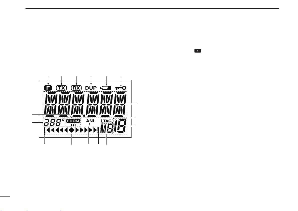
Function display
■......................................................................6
3 BASIC OPERATION.............................................................8–11
Setting a frequency
■.................................................................8
Selecting a weather channel (U.S.A. version only)
■.................8
Receiving
■................................................................................9
ANL function
■...........................................................................9
Channel spacing setting
■..........................................................9
Setting a squelch level
■............................................................9
Transmitting
■.............................................................................9
Low battery indicator
■.............................................................10
Recall function
■......................................................................10
Setting weather alert function
■...............................................11
Accessing the 121.5 MHz emergency frequency
■..................11
Lock function
■.........................................................................11
Side tone function
■.................................................................11
Setting beep tone
■..................................................................11
4 MEMORY OPERATION......................................................12–15
Memory channel selection
■....................................................12
Transferring memory contents
■..............................................12
Programming a memory channel
■..........................................13
Memory names
■.....................................................................14
Clearing the memory contents
■..............................................14
5 SCAN OPERATION............................................................16–17
Scan types
■............................................................................16
COM band scan
■....................................................................16
Memory scan
■........................................................................16
Weather channel scan (U.S.A. version only)
■.........................17
“TAG” channel setting
■............................................................17
6 VOR NAVIGATION (IC-A24 ONLY)....................................18–24
VOR indicators
■......................................................................18
VOR functions
■.......................................................................19
Flying to a VOR station
■.........................................................20
Entering a desired course
■.....................................................22
Crosschecking position
■.........................................................22
Duplex operation (U.S.A. version only)
■.................................24
7 CLONING .................................................................................25
8 BATTERY PACKS ..............................................................26–29
Battery cautions
■....................................................................26
Battery charging
■....................................................................26
Optional battery case
■............................................................27
Optional battery chargers
■.....................................................28
9 SPECIFICATIONS ..............................................................30–31
10 OPTIONS..................................................................................32
11 OPTIONAL HEADSET CONNECTION....................................33
12 SAFETY TRAINING INFORMATION..................................34–35
13 FOR CLASS A UNINTENTIONAL RADIATORS ..................... 36
14 TROUBLESHOOTING .............................................................37
INDEX.......................................................................................38–39