Icom IC-2200H User manual

INSTRUCTION MANUAL
i2200H
VHF TRANSCEIVER
This device complies with Part 15 of the FCC rules. Operation is sub-
ject to the following two conditions: (1) This device may not cause
harmful interference, and (2) this device must accept any interference
received, including interference that may cause undesired operation.


i
FOREWORD
Thank you for purchasing this Icom product. The IC-2200H
VHF TRANSCEIVER
is designed and built with Icom’s superior
technology and craftsmanship. With proper care, this product
should provide you with years of trouble-free operation.
We want to take a couple of moments of your time to thank
you for making your IC-2200H your radio of choice, and hope
you agree with Icom’s philosophy of “technology first.” Many
hours of research and development went into the design of
your IC-2200H.
DD
FEATURES
❍65 W* of high transmit output power
(except Korea/Taiwan versions)
❍Tone squelch, DTCS squelch standard
❍Dual color (amber & green) LCD backlight
❍Remote control microphone available
(optional for some versions)
❍Optional Digital modulator/demodulator
❍Optional DTMF decoder
IMPORTANT
READ ALL INSTRUCTIONS carefully and completely
before using the transceiver.
SAVE THIS INSTRUCTION MANUAL— This in-
struction manual contains important operating instructions for
the IC-2200H.
EXPLICIT DEFINITIONS
WORD DEFINITION
RWARNING!
CAUTION
NOTE
Personal injury, fire hazard or electric shock
may occur.
Equipment damage may occur.
Recommended for optimum use. No risk of
personal injury, fire or electric shock.
Icom, Icom Inc. and the logo are registered trademarks of Icom
Incorporated (Japan) in the United States, the United Kingdom, Ger-
many, France, Spain, Russia and/or other countries.

ii
RWARNING RF EXPOSURE! This device emits
Radio Frequency (RF) energy. Extreme caution should be ob-
served when operating this device. If you have any questions re-
garding RF exposure and safety standards please refer to the
Federal Communications Commission Office of Engineering and
Technology’s report on Evaluating Compliance with FCC Guide-
lines for Human Radio frequency Electromagnetic Fields (OET
Bulletin 65)
RWARNING! NEVER connect the transceiver to an AC
outlet. This may pose a fire hazard or result in an electric shock.
RWARNING! NEVER operate the transceiver while dri-
ving a vehicle. Safe driving requires your full attention—anything
less may result in an accident.
NEVER connect the transceiver to a power source of more
than 16 V DC. This will ruin the transceiver.
NEVER connect the transceiver to a power source using re-
verse polarity. This will ruin the transceiver.
NEVER cut the DC power cable between the DC plug and
fuse holder. If an incorrect connection is made after cutting, the
transceiver may be damaged.
NEVER expose the transceiver to rain, snow or any liquids.
The transceiver may be damaged.
NEVER operate or touch the transceiver with wet hands. This
may result in an electric shock or ruin the transceiver.
NEVER place the transceiver where normal operation of the
vehicle may be hindered or where it could cause bodily injury.
DO NOT
push the PTT when not actually desiring to transmit.
DO NOT allow children to play with any radio equipment con-
taining a transmitter.
During mobile operation, DO NOT operate the transceiver
without running the vehicle’s engine. When the transceiver’s
power is ON and your vehicle’s engine is OFF, the vehicle’s bat-
tery will soon become exhausted.
BE CAREFUL! The transceiver will become hot when op-
erating it continuously for long periods.
AVOID placing the transceiver against walls or putting any-
thing on the top of the transceiver. This will obstruct heat dissi-
pation.
AVOID using or placing the transceiver in direct sunlight or in
areas with temperatures below –10°C (+14˚F) or above +60°C
(+140˚F).
AVOID the use of chemical agents such as benzine or alcohol
when cleaning, as they can damage the transceiver’s surfaces.
USE Icom microphones only (supplied or optional). Other man-
ufacturer’s microphones have different pin assignments and may
damage the transceiver if attached.
PRECAUTION

iii
SUPPLIED ACCESSORIES AND OPTIONS
■Supplied Accessories
qMicrophone (HM-133V)* . . . . . . . . . . . . . . . . . . . . . . . . . 1
wFuse (20 A) . . . . . . . . . . . . . . . . . . . . . . . . . . . . . . . . . . . 1
eDC power cable (3 m) . . . . . . . . . . . . . . . . . . . . . . . . . . . 1
rMobile mounting bracket . . . . . . . . . . . . . . . . . . . . . . . . 1
tMounting screws, nuts and washers . . . . . . . . . . . . 1 set
yMicrophone hanger†. . . . . . . . . . . . . . . . . . . . . . . . . . . . 1
uInsulation sheet‡. . . . . . . . . . . . . . . . . . . . . . . . . . . . . . . 1
*HM-118TN
DTMF MICROPHONE
supplied versions are also available.
†Depending on version.
‡Used for optional unit installation, see p.91 for details.
■Options
UT-108
DTMF DECODER UNIT
UT-115
DIGITAL UNIT
HM-118TAN/TN
DTMF MICROPHONES
HM-118N
HAND MICROPHONE
HM-133V
REMOTE
-
CONTROL MICROPHONE
SP-10
EXTERNAL SPEAKER
OPC-440/OPC-647
MIC EXTENSION CABLES
OPC-441
SPEAKER EXTENSION CABLE
OPC-1132/OPC-347
DC POWER CABLES
OPC-589
ADAPTER CABLE
CS-2200H
CLONING SOFTWARE
+ OPC-478/OPC-478U
CLONING CABLE
OPC-474
CLONING CABLE
qwe
rtyu

iv
TABLE OF CONTENTS
FOREWORD ........................................................................................... i
IMPORTANT ............................................................................................ i
EXPLICIT DEFINITIONS ......................................................................... i
PRECAUTION ........................................................................................ ii
SUPPLIED ACCESSORIES AND OPTIONS ......................................... iii
TABLE OF CONTENTS ......................................................................... iv
QUICK REFERENCE GUIDE ............................................................ I–VI
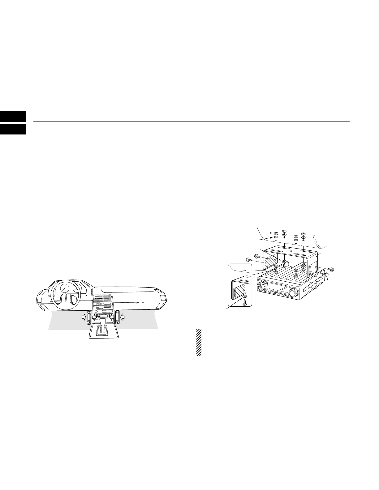
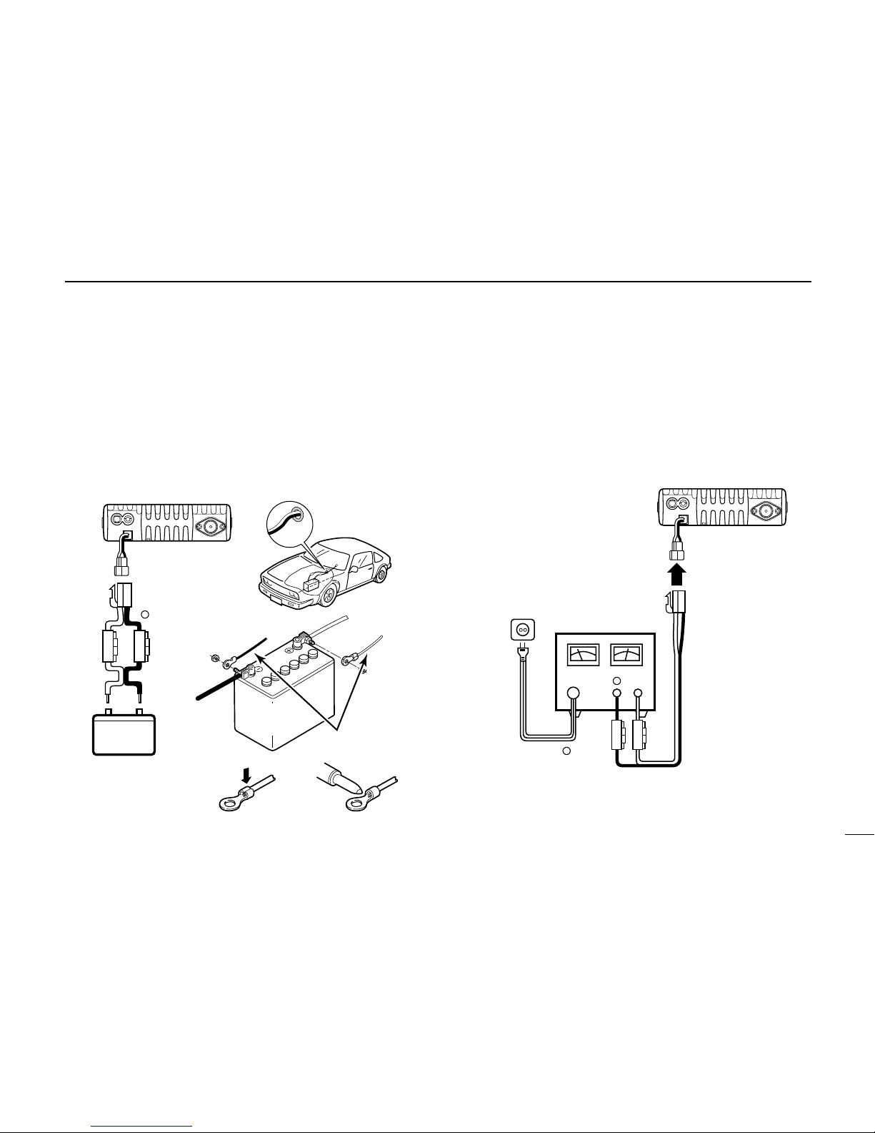
■Installation ....................................................................................... I
■Your first contact ........................................................................... IV
■Repeater operation ........................................................................ V
■Programming memory .................................................................. VI
1 PANEL DESCRIPTION ................................................................. 1–8
■Front panel ..................................................................................... 1
■Function display ............................................................................. 3
■Rear panel ..................................................................................... 5
■Microphone (HM-133V) .................................................................. 6
■Microphone keypad ........................................................................ 7
2 SETTING A FREQUENCY .......................................................... 9–12
■Preparation .................................................................................... 9
■Using the tuning dial ...................................................................... 9
■Using the keypad ......................................................................... 10
■Using the [Y]/[Z] keys ................................................................. 10
■Tuning step selection ................................................................... 11
■Lock functions .............................................................................. 12
3 BASIC OPERATION ................................................................. 13–16
■Receiving ..................................................................................... 13
■Monitor function ........................................................................... 13
■Audio mute function ..................................................................... 14
■Squelch attenuator ....................................................................... 14
■S-meter squelch ........................................................................... 15
■Transmitting ................................................................................. 15
■Selecting output power ................................................................ 16
■One-touch PTT function ............................................................... 16
4 REPEATER OPERATION ......................................................... 17–23
■Accessing a repeater ................................................................... 17
■Subaudible tones ......................................................................... 19
■Offset frequency .......................................................................... 21
■Repeater lockout .......................................................................... 21
■Reversed duplex mode ................................................................ 22
■Auto repeater ............................................................................... 23
5 MEMORY OPERATION ............................................................ 24–34
■General description ...................................................................... 24
■Memory channel selection ........................................................... 24
■Programming a memory channel ................................................. 25
■Transferring memory contents ..................................................... 27
■Programming channel names ....................................................... 29
■Memory clearing .......................................................................... 31
■Memory bank selection ................................................................ 32
■Memory bank setting .................................................................... 33
■Transferring bank contents .......................................................... 34
6 CALL CHANNEL OPERATION ................................................ 35–36
■Call channel selection .................................................................. 35
■Call channel transferring .............................................................. 35
■Programming a call channel ........................................................ 36
7 SCAN OPERATION .................................................................. 37–42
■Scan types ................................................................................... 37
■Scan start/stop ............................................................................. 38
■Scan edges programming ............................................................ 39
■Skip channel setting ..................................................................... 41
■Scan resume condition ................................................................ 42

v
8 PRIORITY WATCH .................................................................... 43–44
■Priority watch types ...................................................................... 43
■Priority watch operation ............................................................... 44
9 DTMF MEMORY ENCODER ..................................................... 45–47
■Programming a DTMF code ......................................................... 45
■Transmitting a DTMF code .......................................................... 46
■DTMF speed ................................................................................ 47
10 POCKET BEEP AND TONE SQUELCH ................................... 48–51
■Pocket beep operation ................................................................. 48
■Tone/DTCS squelch operation ..................................................... 50
■Tone scan ..................................................................................... 51
11 PAGER/CODE SQUELCH (Required Optional UT-108).......... 52–57
■Pager function .............................................................................. 52
■Code programming ...................................................................... 52
■Pager operation ........................................................................... 55
■Code squelch ............................................................................... 57
12 DIGITAL MODE OPERATION (Required Optional UT-115) .... 58–73
■Digital mode operation ................................................................. 58
■Call sign programming ................................................................. 58
■Digital voice mode operation ........................................................ 61
■When receiving a Digital call ........................................................ 63
■Break-in communication .............................................................. 65
■Emergency communication .......................................................... 66
■Digital code/Call sign squelch operation ...................................... 67
■Slow data communication ............................................................ 68
■Other setting items ....................................................................... 69
■GPS operation ............................................................................. 72
13 OTHER FUNCTIONS ................................................................ 74–87
■Set mode ...................................................................................... 74
■Initial set mode ............................................................................. 79
■Weather channel operation .......................................................... 83
■Microphone keys .......................................................................... 84
■Partial reset .................................................................................. 85
■All reset ........................................................................................ 85
■Data cloning ................................................................................. 86
14 SPECIFICATIONS ........................................................................... 88
15 MAINTENANCE ........................................................................ 89–91
■Troubleshooting ........................................................................... 89
■Fuse replacement ........................................................................ 90
■Optional unit installation ............................................................... 91
16 CE .................................................................................................... 92
17 MODE ARRANGEMENT ........................................................... 93–94
1
2
3
4
5
6
7
8
9
10
11
12
13
14
15
16
17

I
QUICK REFERENCE GUIDE
■Installation
DLocation
Select a location which can support the weight of the trans-
ceiver and does not interfere with driving in any way. We rec-
ommend the locations shown in the diagram below.
NEVER place the transceiver where normal operation of the
vehicle may be hindered or where it could cause bodily injury.
NEVER place the transceiver where air bag deployment may
be obstructed.
DO NOT place the transceiver where hot or cold air blows di-
rectly onto it.
AVOID placing the transceiver in direct sunlight.
DUsing the mounting bracket
➀Drill 4 holes where the mounting bracket is to be installed.
• Approx. 5.5–6 mm (1⁄4″) when using nuts; approx. 2–3 mm (1⁄8″)
when using self-tapping screws.
➁Insert the supplied screws, nuts and washers through the
mounting bracket and tighten.
➂Adjust the angle for the clearest view of the function dis-
play.
IMPORTANT!
Detailed installation notes for Icom mobile transceivers to
be fitted into vehicles are available. Contact your Icom
dealer or distributor.
Nut
Spring washer
Flat washer
When using
self-tapping
screws
Spring
washer
Mounting
nut
Mounting
bracket

II
QUICK REFERENCE GUIDE
DBattery connection
☞NEVER connect the transceiver directly to a 24 V battery.
☞DO NOT use the cigarette lighter socket for power con-
nections. (See p. 5 for details)
Attach a rubber grommet when passing the DC power cable
through a metal plate to prevent short circuiting.
• CONNECTING TO A DC POWER SOURCE
• See p. 90 for fuse replacement.
DDC power supply connection
Use a 13.8 V DC power supply with at least 15 A capacity.
Make sure the ground terminal of the DC power supply is
grounded.
• CONNECTING TO A DC POWER SUPPLY
• See p. 90 for fuse replacement.
DC power
supply 13.8 V
to an
AC
outlet
Fuses
20 A
black
red⊕
−
⊕
−
IC-2200H
Fuses
20 A
Crimp Solder
black
red⊕
Grommet
IC-2200H
−
12 V
12 V
battery Supplied
DC power cable
NOTE:
Use terminals for the
cable connections.
+red
_black

III
QUICK REFERENCE GUIDE
DAntenna installation
•Antenna location
To obtain maximum performance from the transceiver, select
a high-quality antenna and mount it in a good location. A non-
radial antenna should be used when using a magnetic mount.
•Antenna connector
The antenna uses a PL-259 connector.
• PL-259 CONNECTOR
qSlide the coupling ring
down. Strip the cable
jacket and soft solder.
wStrip the cable as shown
at left. Soft solder the cen-
ter conductor.
eSlide the connector body
on and solder it.
rScrew the coupling ring
onto the connector body.
(10 mm ≈3⁄8 in)
NOTE: There are many publications covering proper an-
tennas and their installation. Check with your local dealer
for more information and recommendations.
DConnecting a microphone
Connect a microphone to the eight-pin modular socket on the
front panel of the transceiver.
*HM-133V; A different microphone may be
supplied with some versions of the IC-2200H.
30 mm
10 mm (soft solder)
10 mm
1–2 mm
solder solder
Soft
solder
Coupling ring
to antenna
Roof-mount antenna
(Drill a hole or use a magnetic mount.)
Gutter-mount antenna
Trunk-mount
antenna

IV
QUICK REFERENCE GUIDE
■Your first contact
Now that you have your IC-2200H installed in your car or
shack, you are probably excited to get on the air. We would
like to take you through a few basic operation steps to make
your first “On The Air” an enjoyable experience.
1. Turning ON the transceiver
Before powering up your IC-2200H, you may want to make
sure the audio volume and squelch level controls are set in
9–10 o’clock positions.
Although you have purchased a brand new transceiver, some
settings may be changed from the factory defaults because
of the QC process. Resetting the CPU is necessary to start
from factory default.
➥While pushing [SET ] and [S.MW ], push
[PWR] for 1 sec. to reset the CPU.
2. Tune the desired frequency
[DIAL] will allow you to dial in the frequency you want to op-
erate. Pages 9 and 11 will instruct you on how to set the tun-
ing speed.
Using the HM-133V
You can directly enter the frequency with the HM-133V keypad.
We hope these pointers have been helpful. Now you
are ready to call CQ.
LOCK
S
E
T
ANM
MONI
DUP
LOW
T-SCAN
TONE
PRIO
M/CALL
SCAN
V/MHz
DIGITAL PRIO AO BUSY
MUTE
NAR
MID
LOW
LOCK
S
E
T
ANM
MONI
DUP
LOW
T-SCAN
TONE
PRIO
M/CALL
SCAN
V/MHz
DIGITAL PRIO AO BUSY
MUTE
NAR
MID
LOW
LOCK
S
E
T
ANM
MONI
DUP
LOW
T-SCAN
TONE
PRIO
M/CALL
SCAN
V/MHz
DIGITAL PRIO AO BUSY
MUTE
NAR
MID
LOW
LOCK
S
E
T
ANM
MONI
DUP
LOW
T-SCAN
TONE
PRIO
M/CALL
SCAN
V/MHz
DIGITAL PRIO AO BUSY
MUTE
NAR
MID
LOW
[EXAMPLE]: Setting frequency to 145.3625 MHz.
Push
Push
Push
Push
[DIAL]
MWLOCK
[PWR] [SET LOCK] [S.MW MW]
Set both [VOL] and [SQL] controls to
9–10 o’clock positions.
[VOL]
[SQL]

V
QUICK REFERENCE GUIDE
■Repeater operation
1. Setting duplex
Push [LOW ] for 1 sec. once or twice to select minus
duplex or plus duplex.
• The USA version has an auto repeater function, therefore, setting
duplex is not required.
2. Repeater tone
Push [TONE ] several times until “ ” appears, if the
repeater requires a subaudible to be accessed.
Using the HM-133V
Plus or minus duplex selection and the repeater tone setting
can be made easily via HM-133V.
Push [
DUP
–7(TONE)] for minus duplex; [
DUP
+8(TSQLSS)]
for plus duplex selection, push [FUNC] then [
DUP
–7(TONE)]
to turn the repeater tone ON.
LOCK
S
E
T
ANM
MONI
DUP
LOW
T-SCAN
TONE
PRIO
M/CALL
SCAN
V/MHz
DIGITAL PRIO AO BUSY
MUTE
NAR
MID
LOW
LOCK
S
E
T
ANM
MONI
DUP
LOW
T-SCAN
TONE
PRIO
M/CALL
SCAN
V/MHz
DIGITAL PRIO AO BUSY
MUTE
NAR
MID
LOW
LOCK
S
E
T
ANM
MONI
DUP
LOW
T-SCAN
TONE
PRIO
M/CALL
SCAN
V/MHz
DIGITAL PRIO AO BUSY
MUTE
NAR
MID
LOW
Push
Push , then
Push
LOCK
S
E
T
ANM
MONI
DUP
LOW
T-SCAN
TONE
PRIO
M/CALL
SCAN
V/MHz
DIGITAL PRIO AO BUSY
MUTE
NAR
MID
LOW
T-SCAN
LOCK
S
E
T
ANM
MONI
DUP
LOW
T-SCAN
TONE
PRIO
M/CALL
SCAN
V/MHz
DIGITAL PRIO AO BUSY
MUTE
NAR
MID
LOW
DUP

The IC-2200H has a total of 207 memory channels (including
6 scan edges and 1 call channel) for storing often used oper-
ating frequency, repeater settings, etc.
1. Setting a frequency
In VFO mode, set the desired operating frequency with re-
peater, tone and tuning steps, etc.
2. Selecting a memory channel
Momentarily push [S.MW ], then rotate [DIAL] to select
the desired memory channel.
•“M” indicator and memory channel number blink.
3. Writing a memory channel
Push and hold [S.MW ] for 1 sec. to program.
• 3 beeps sound
• Memory channel number automatically increases when continuing
to push [S.MW ] after programming.
Using the HM-133V
qIn VFO mode, set the desired operating frequency, includ-
ing offset direction, tone settings, etc.
wPush [FUNC] then [
CLR
A(MW)].
•“M” indicator and memory channel number blink.
ePush [YY]/[ZZ]to select the desired memory channel.
rPush [FUNC] then push [
CLR
A(MW)] for 1 sec. to pro-
gram.
• 3 beeps sound
• Memory channel number automatically increases when continu-
ing to push [
CLR
A(MW)] after programming.
LOCK
S
E
T
ANM
MONI
DUP
LOW
T-SCAN
TONE
PRIO
M/CALL
SCAN
V/MHz
DIGITAL PRIO AO BUSY
MUTE
NAR
MID
LOW
Push ,
then
MW
MW
LOCK
S
E
T
ANM
MONI
DUP
LOW
T-SCAN
TONE
PRIO
M/CALL
SCAN
V/MHz
DIGITAL PRIO AO BUSY
MUTE
NAR
MID
LOW
[S.MW MW] [DIAL]
MW
■Programming memory channels
VI
QUICK REFERENCE GUIDE

■Front panel
qPOWER KEY [PWR]
Turns power ON and OFF when pushed for 1 sec.
wMEMORY WRITE KEY [S.MW ] (p. 25)
➥Selects a memory channel for programming.
➥Programs the selected memory channel when pushed
for 1 sec.
• Continue to hold the key to increment the memory channel
automatically.
eMICROPHONE CONNECTOR
Connects the supplied microphone.
rVOLUME CONTROL [VOL] (p. 13)
Adjusts the audio level.
tSQUELCH CONTROL [SQL] (p. 13)
Varies the squelch level.
• The RF attenuator activates and increases the attenuation when
rotated clockwise to the center position and further.
MW
PWR
S.MW
MW
BANK
OPT
Function display (p. 3)
!0oiuy
q
w
e
rt
!3
!1 !2
1
PANEL DESCRIPTION
1

2
1
PANEL DESCRIPTION
1
ySET•LOCK KEY [SET ]
➥Enters set mode when pushed. (p. 74)
➥Keys the lock function ON and OFF when pushed for
1 sec. (p. 12)
uMONITOR•CHANNEL NAME KEY [MONI ]
➥Push to switch the monitor function ON and OFF. (p. 13)
➥In memory and call channel mode, switches the channel
names or number ON and OFF. (p. 29)
iOUTPUT POWER•DUPLEX KEY [LOW ]
➥Each push changes the output power selection. (p. 16)
➥Select DUP–, DUP+ and simplex operation when
pushed for 1 sec. (p. 17)
oTONE•TONE SCAN KEY [TONE ]
➥Each push selects a tone function. (pgs. 17, 48)
• Tone encoder, pocket beep, tone squelch or tone function
OFF can be selected.
➥Push for 1 sec. to start/stop the tone scan function.
(p. 51)
❍While in the digital mode operation with the installing an
optional Digital unit UT-115.
➥Each push select the digital code (CSQL) squelch func-
tion, call sign (DSQL) squelch, pocket beep function
(CSQL or DSQL). (p. 67)
!0 MEMORY/CALL•PRIORITY KEY [M/CALL ]
➥Push to select and toggle memory, call and weather
channel* modes. (pgs. 24, 35, 83)
*Weather channels available for USA versions only.
➥Starts priority watch when pushed for 1 sec. (p. 44)
!1 VFO/MHz TUNING•SCAN KEY [V/MHz ]
➥Selects and toggles VFO mode and 1 MHz (or 10 MHz
for some versions) tuning when pushed. (p. 9)
➥Starts scan when pushed for 1 sec. (p. 38)
• Cancels a scan when pushed during a scan.
!2 BANK•OPTION KEY [BANK ]
➥Push to select memory bank condition during memory
mode. (p. 32)
➥Push for 1 sec. to enter the DTMF or option set mode.
!3 TUNING DIAL [DIAL]
Selects the operating frequency (p. 9), memory channel
(p. 24), the setting of the set mode item and the scanning
direction (p. 38).
DMicrophone connector (front panel view)
q+8 V DC output (Max. 10 mA)
wChannel up/down
e8 V control IN
rPTT
tGND (microphone ground)
yMIC (microphone input)
uGND
iData IN
qi
OPT
SCAN
PRIO
T-SCAN
DUP
ANM
LOCK

3
1PANEL DESCRIPTION
■Function display
qFREQUENCY READOUT
Shows the operating frequency, channel names, set mode
contents, etc.
• Frequency decimal point flashes while scanning. (p. 38)
• “d” appears in place of the 1st digit while the DTMF memory
function is in use. (p. 45)
wTRANSMIT INDICATOR
➥Appears while transmitting. (p. 15)
➥Flashes while transmitting with the one-touch PTT func-
tion. (p. 16)
eAUDIO MUTE INDICATOR (p. 14)
Appears when the audio mute function is activated via mi-
crophone control.
rNARROW MODE INDICATOR (p. 78)
Appears when the narrow mode is selected.
Narrow mode is not available with some versions.
tOUTPUT POWER INDICATORS (p. 16)
“LOW” appears when low output power; “MID” and “LOW”
appear when mid low output power; “MID” appears when
middle output power is selected.
• Mid. low power is not available with some versions.
LOCK
S
E
T
ANM
MONI
DUP
LOW
T-SCAN
TONE
PRIO
M/CALL
SCAN
V/MHz
DIGITAL PRIO AO BUSY
MUTE
NAR
MID
LOW
!7 !3!4
i
!5!6
!0
!2 !1
u
o
w
y
t
e
r
q

4
1
PANEL DESCRIPTION
1
yKEY INDICATORS
Indicate the function(s) of the front panel keys directly
below the function display.
uSKIP INDICATOR (p. 41)
Appears when the selected memory channel is specified
as a skip channel.
iMEMORY CHANNEL NUMBER INDICATORS
➥Shows the selected memory channel number. (p. 24)
➥“C” appears when the call channel is selected. (p. 35)
oMEMORY INDICATOR (p. 24)
Appears when memory mode is selected.
!0S/RF INDICATORS
➥Shows the relative signal strength while receiving sig-
nals. (p. 13)
➥Shows the output power level while transmitting. (p. 16)
!1BUSY INDICATOR (p. 13)
➥Appears when a signal is being received or the squelch
is open.
➥Flashes while the monitor function is activated.
!2AUTO POWER-OFF INDICATOR (p. 81)
Appears while the auto power-off function is in use.
!3PRIORITY WATCH INDICATOR (p. 44)
Appears while the priority watch is activated; blinks while
the watch is paused.
!4DIGITAL INDICATOR (p. 61)
Appears when digital mode is selected.
!5LOCK INDICATOR (p. 12)
Appears when the lock function is activated.
!6TONE INDICATORS
➥“ ” appears while the subaudible tone encoder is in
use. (p. 17)
➥“ ” appears while the tone (CTCSS) squelch function is
in use. (p. 48)
➥“ ” appears while the tone (DTCS) squelch function is
in use. (p. 48)
➥“ ” appears with the “ ” or “ ” indicator while the
pocket beep function (CTCSS or DTCS) is in use. (p. 48)
❍While in the digital mode operation with the installing an
optional Digital unit UT-115.
➥“ ” appears while the digital code (CSQL) squelch func-
tion is in use. (p. 67)
➥“ ” appears while the call sign (DSQL) squelch function
is in use. (p. 67)
➥“ ” appears with the “ ” or “ ” indicator while the
pocket beep function (CSQL or DSQL) is in use. (p. 67)
!7DUPLEX INDICATORS (p. 17)
“+” appears when plus duplex, “–” appears when minus
duplex operation is selected.

5
1PANEL DESCRIPTION
■Rear panel
qSPEAKER JACK [SP]
Accepts an 8 Ωspeaker.
• Audio output power is more than 2.4 W.
wDATA JACK [DATA]
Connects to a PC or GPS receiver via an RS-232C cable
(D-sub 9-pin) for data communication in the RS-232C for-
mat.
ePOWER RECEPTACLE [DC13.8V]
Accepts 13.8 V DC ±15% with the supplied DC power
cable.51
NOTE: DO NOT use a cigarette lighter socket as a
power source when operating in a vehicle. The plug
may cause voltage drops and ignition noise may be su-
perimposed onto transmit or receive audio.
rANTENNA CONNECTOR [ANT]
Connects a 50 Ωantenna with a PL-259 connector and a
50 Ωcoaxial cable.
Pin 2 (RxD), Pin 3 (TxD), Pin 5 (GND)
to [DATA] jack
TxD
2.5(d) mm
GND
RxD
1
5
69
RS-232C (DB-9 female)
r
e
q
w
Make sure the connection between transceiver and PC, oth-
erwise misreading may occur for data communication.

6
1
PANEL DESCRIPTION
1
■Microphone (HM-133V*)
qVFO/LOCK KEY [VFO/LOCK]
➥Push to select VFO mode. (p. 9)
➥Push for 1 sec. to switch the lock function ON and OFF.
(p. 12)
wPTT SWITCH
➥Push and hold to transmit; release to receive.
➥Switches between transmitting and receiving while the
one-touch PTT function is in use. (p. 16)
eUP/DOWN KEYS [Y]/[Z]
➥Push either key to change operating frequency, mem-
ory channel, set mode setting, etc. (pgs. 10, 24)
➥Push either key for 1 sec. to start scanning. (p. 38)
rACTIVITY INDICATOR
➥Lights red while any key, except [FUNC] and [DTMF-S],
is pushed, or while transmitting.
➥Lights orange while the microphone keypad lock func-
tion is activated.
➥Lights green while the one-touch PTT function is in use.
tKEYPAD (pgs. 7, 8)
yFUNCTION INDICATOR
➥Lights orange while [FUNC] is activated—indicates the
secondary function of keys can be accessed.
➥Lights green when [DTMF-S] is activated—DTMF sig-
nals can be transmitted with the keypad.
uFUNCTION KEY [FUNC] (pgs. 7, 8)
iDTMF MEMORY SELECT KEY [DTMF-S] (p. 46)
oFUNCTION KEYS [F-1]/[F-2] (p. 84)
Program and re-call your desired transceiver conditions.
!0BANK/OPTION KEY [BANK/OPTION]
➥Push to selects memory bank condition during memory
mode. (p. 32)
➥Push for 1 sec. to enter the DTMF or option set mode.
!1MEMORY/CALL KEY [MR/CALL]
➥Push to select memory mode. (p. 24)
➥Push for 1 sec. to select call channel. (p. 35)
q
e
r
t
Mic element
y
u
i
o
!0
!1
w
*
A different microphone
may be supplied de-
pending on version.

7
1PANEL DESCRIPTION
■Microphone keypad
KEY FUNCTION SECONDARY FUNCTION ( +key) OTHER FUNCTIONS
Switches between opening and closing the
squelch. (p. 13)
Starts and stops scanning. (p. 38)
Starts and stops priority watch. (p. 44)
Selects high output power. (p. 16)
Selects mid. output power. (p. 16)
Selects low output power (p. 16)
Selects minus duplex operation. (p. 18)
Selects plus duplex operation. (p. 18)
Selects simplex operation. (p. 18)
No primary function.
In memory mode switches the channel names
or number indication ON and OFF. (p. 30)
Starts and stops tone scanning. (p. 51)
Turns the one-touch PTT function ON and
OFF. (p. 16)
Turns the DTCS squelch ON. (p. 50)
*Turns the DSQL function. (p. 67)
Turns the DTCS pocket beep function ON. (p. 49)
*Turns the DSQL pocket beep function.
Turns the DTMF memory encoder function
ON. (p. 45)
Turns the subaudible tone encoder ON.
(p. 18)
Turns the CTCSS pocket beep function ON.(p. 49)
*Turns the CSQL pocket beep function.
Turns the tone squelch function ON.
(p. 50)
*Turns the CSQL function. (p. 67)
Sends a 1750 Hz tone signal while pushing
and holding. (p. 20)
After pushing :
Transmits the appropriate
DTMF code. (pgs. 20, 46)
When the DTMF memory en-
coder is activated, push [0] to
[9] to transmit the appropriate
DTMF memory contents.
(p. 46)
*While in the digital mode operation with the installing an optional Digital unit UT-115.
Other manuals for IC-2200H
7
Table of contents
Other Icom Transceiver manuals

Icom
Icom IC-120 User manual

Icom
Icom IC-V201 User manual

Icom
Icom IC-F6062 User manual

Icom
Icom IC-775 Operating manual

Icom
Icom IC-M23 User manual

Icom
Icom IC-9700 Installation and operating instructions

Icom
Icom IC-T70A User manual

Icom
Icom IC-H19S2 User manual

Icom
Icom IC-A200 User manual

Icom
Icom IC-M45 User manual