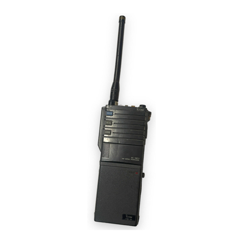
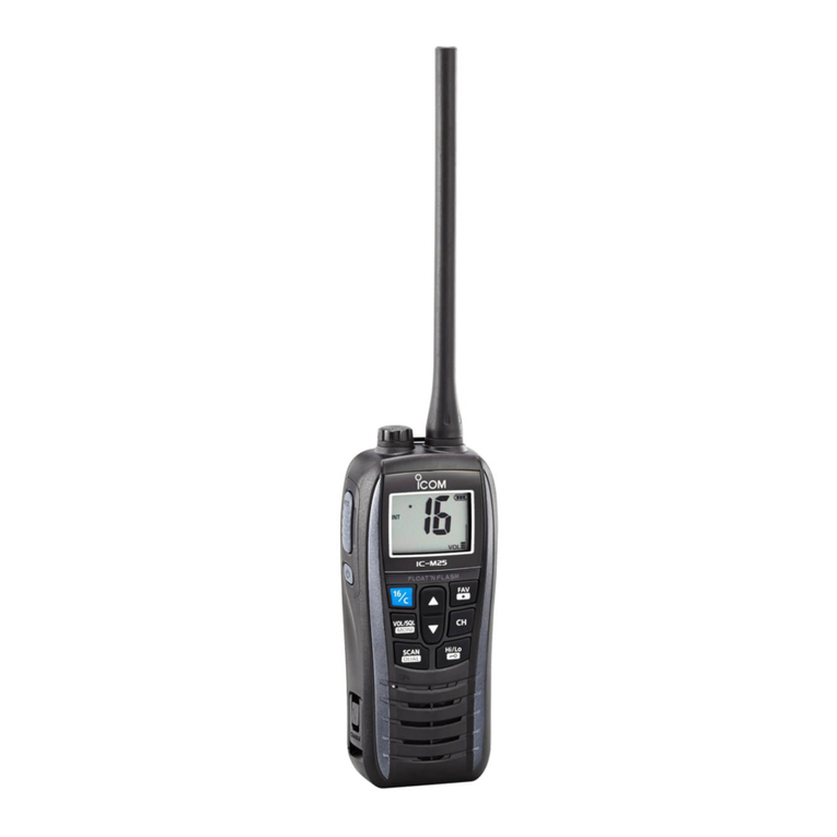
Icom IC-V3MR User manual

i
INTRODUCTION
Thank you for choosing this Icom product. This
product was designed and built with Icom’s state of
the art technology and craftsmanship. With proper
care, this product should provide you with years of
trouble-free operation.
IMPORTANT
FIRST, CAREFULLY READ INSTRUCTIONS that is
provided with the transceiver.
READ ALL INSTRUCTIONS carefully and completely
before using the transceiver.
SAVE THIS INSTRUCTION MANUAL— This
instruction manual contains important operating
instructions for the IC-V3MR.
EXPLICIT DEFINITIONS
WORD DEFINITION
RDANGER! Personal death, serious injury or an
explosion may occur.
RWARNING! Personal injury, fire hazard or electric
shock may occur.
CAUTION Equipment damage may occur.
NOTE
If disregarded, inconvenience only.
No risk of personal injury, fire or
electric shock.
Icom, Icom Inc. and the Icom logo are registered
trademarks of Icom Incorporated (Japan) in Japan,
the United States, the United Kingdom, Germany,
France, Spain, Russia, Australia, New Zealand, and/or
other countries.
All other products or brands are registered trademarks
or trademarks of their respective holders.
Icom is not responsible for the destruction, damage
to, or performance of any Icom or non-Icom
equipment, if the malfunction is because of:
• Force majeure, including, but not limited to, fires,
earthquakes, storms, floods, lightning, other
natural disasters, disturbances, riots, war, or
radioactive contamination.
• The use of Icom transceivers with any equipment
that is not manufactured or approved by Icom.

ii
INTRODUCTION
RDANGER! NEVER operate the transceiver near
unshielded electrical blasting caps or in an explosive
atmosphere. This could cause an explosion and
death.
RWARNING! NEVER use or charge Icom battery
packs with non-Icom transceivers or non-Icom
chargers. Only Icom battery packs are tested and
approved for use with Icom transceivers or charged
with Icom chargers. Using third-party or counterfeit
battery packs or chargers may cause smoke, fire, or
cause the battery to burst.
RWARNING! NEVER hold the transceiver so that
the antenna is very close to, or touching exposed
parts of the body, especially the face or eyes, while
transmitting.
RWARNING! NEVER operate the transceiver with
earphones, a headset, or other audio accessories
at high volume levels. The continuous high volume
operation may cause a ringing in your ears. If you
experience the ringing in your ears, reduce a volume
level or discontinue use.
CAUTION: DO NOT use or leave the transceiver in
excessively dusty environments. This could damage
the transceiver.
CAUTION: DO NOT short the terminals of the battery
pack. Shorting may occur if the terminals touch metal
objects such as a key, so be careful when placing the
battery packs (or the transceiver) in bags, and so on.
Carry them so that shorting cannot occur with metal
objects. Shorting may damage not only the battery
pack but also the transceiver.
CAUTION: DO NOT change the internal settings
of the equipment. This may reduce equipment
performance and/or cause extensive and expensive
damage to the equipment. The equipment warranty
does not cover any problems caused by unauthorized
internal adjustments.
CAUTION: DO NOT operate the transceiver unless
the flexible antenna, battery pack, and jack cover
are securely attached to the transceiver and that the
antenna and battery pack are dry before attachment.
Exposing the inside of the transceiver to dust or water
will result in serious damage to the transceiver.
CAUTION: DO NOT operate the transceiver while
driving a vehicle. Safe driving requires your full
attention—anything less may result in an accident.
CAUTION: DO NOT use harsh solvents such as
Benzine or alcohol when cleaning. This could damage
the equipment surfaces. If the surface becomes dusty
or dirty, wipe it clean with a soft, dry cloth.
NOTE: DO NOT use or leave the transceiver in areas
with temperatures below –30°C (–22°F) or above
+60°C (+140°F), or in areas subject to direct sunlight,
such as the dashboard.
DO NOT push PTT unless you actually intend to
transmit.
KEEP the transceiver away from heavy rain and
never immerse it in water. The transceiver meets
IP54* requirements for dust-protection and splash
resistance.
However, once the transceiver has been dropped,
dust-protection and splash resistance cannot be
guaranteed due to the fact that the transceiver may be
cracked or the waterproof seal damaged, and so on.
* Only when the battery pack and jack cover are
attached.
NEVER place the transceiver in an insecure place to
avoid inadvertent use by unauthorized persons.
BE CAREFUL! The transceiver may become hot after
continuously transmitting for long periods of time.
Even when the transceiver power is OFF, a slight
current still flows in the circuits. Remove the battery
pack from the transceiver when not using it for a long
time. Otherwise, the installed battery pack or batteries
will become exhausted, and will need to be recharged
or replaced.
PRECAUTIONS

iii
INTRODUCTION
Your Icom radio generates RF
electromagnetic energy while transmitting.
This radio is designed for and classified as
for “Occupational Use Only.” This means
it must be used only during the course of
employment by individuals aware of the hazards, and
the ways to minimize such hazards. This radio is NOT
intended for use by the “General Population” in an
uncontrolled environment.
This radio has been tested and complies with the FCC
RF exposure limits for “Occupational Use Only.” In
addition, your Icom radio complies with the following
Standards and Guidelines with regard to RF energy
and electromagnetic energy levels and evaluation of
such levels for exposure to humans:
• FCC KDB Publication 447498 D03, Evaluating
Compliance with FCC Guidelines for Human
Exposure to Radio Frequency Electromagnetic
Fields.
• American National Standards Institute (C95.1-
2019), IEEE Standard for Safety Levels with
Respect to Human Exposure to Radio Frequency
Electromagnetic Fields, 0 Hz to 300 GHz.
• American National Standards Institute (C95.3-
2002), IEEE Recommended Practice for
the Measurement of Potentially Hazardous
Electromagnetic Fields– RF and Microwave.
• The antenna, battery, belt clip, speaker-
microphone, and other accessories that are
listed in “OPTIONS” on this instruction manual,
are authorized for use with this product. Use
of accessories other than those specified may
result in RF exposure levels exceeding the FCC
requirements for wireless RF exposure.
To ensure that your expose to RF
electromagnetic energy is within the FCC
allowable limits for occupational use,
always adhere to the following guidelines:
• DO NOT operate the radio without a proper
antenna attached, as this may damage the radio
and may also cause you to exceed FCC RF
exposure limits. A proper antenna is the antenna
supplied with this radio by the manufacturer or an
antenna specifically authorized by the manufacturer
for use with this radio.
• DO NOT transmit for more than 50% of the total
radio use time (“50% duty cycle”). Transmitting
more than 50% of the time can cause FCC RF
exposure compliance requirements to be exceeded.
The radio is transmitting when the status indicator
lights red. You can cause the radio to transmit by
pushing the “PTT” switch.
• ALWAYS keep the antenna at least 2.5 cm (1 inch)
away from the body when transmitting, and only
use the Icom belt-clip listed in “OPTIONS” on this
instruction manual when attaching the radio to your
belt, or other place, to ensure FCC RF exposure
compliance requirements are not exceeded.
The information listed above provides the user with
the information needed to make him or her aware of
RF exposure, and what to do to assure that this radio
operates within the FCC RF exposure limits of this
radio.
Electromagnetic Interference/Compatibility
During transmissions, your Icom radio generates RF
energy that can possibly cause interference with other
devices or systems. To avoid such interference, turn
OFF the radio in areas where signs are posted to
do so. DO NOT operate the transmitter in areas that
are sensitive to electromagnetic radiation such as
hospitals, aircraft, and blasting sites.
Occupational/Controlled Use
The radio transmitter is used in situations in which
persons are exposed as a consequence of their
employment, provided those persons are fully aware
of the potential for exposure and can exercise control
over their exposure.
CAUTIO N
WARNING
SAFETY TRAINING INFORMATION
iv
INTRODUCTION
This equipment has been tested and found to
comply with the limits for a Class B digital device,
pursuant to part 15 of the FCC Rules. These limits
are designed to provide reasonable protection against
harmful interference in a residential installation. This
equipment generates, uses, and can radiate radio
frequency energy and, if not installed and used in
accordance with the instructions, may cause harmful
interference to radio communications. However, there
is no guarantee that interference will not occur in a
particular installation. If this equipment does cause
harmful interference to radio or television reception,
which can be determined by turning the equipment
off and on, the user is encouraged to try to correct
the interference by one or more of the following
measures:
• Reorient or relocate the receiving antenna.
• Increase the separation between the equipment
and receiver.
• Connect the equipment into an outlet on a
circuit different from that to which the receiver is
connected.
• Consult the dealer or an experienced radio/TV
technician for help.
CAUTION: Changes or modifications to this
transceiver, not expressly approved by Icom Inc.,
could void your authority to operate this transceiver
under FCC regulations.
This device complies with Part 15 of the FCC Rules.
Operation is subject to the condition that this device
does not cause harmful interference.
• DO NOT operate or adjust all controls,
adjustments, and switches without resulting in a
violation of the FCC rules.
• DO NOT replace any transmitter components
such as crystal, semiconductor, and so on. It could
result in a violation of the FCC rules.
Adjustment of this radio should be performed by or
under the immediate supervision and responsibility
of Icom Inc. or:
• A person certified as technically qualified to
perform transmitter maintenance and repair duties
in the private land mobile services.
• Services by an organization or committee
representative of the private land mobile services
user.
• Since FCC Part 95.2725 requires monitoring the
channel before transmit, Lock-out (Busy lockout)
must be enabled if Moni (Monitor) button was
disabled.
FCC INFORMATION

1-1
Section 1ACCESSORIES
Supplied accessories �����������������������������������������������������������������������1-2
Belt clip���������������������������������������������������������������������������������������������1-2
Flexible antenna �������������������������������������������������������������������������������1-2
Battery pack �������������������������������������������������������������������������������������1-3
Jack cover ����������������������������������������������������������������������������������������1-3

1ACCESSORIES
1-2
Supplied accessories
Battery pack
(BP-298)
Battery charger
(BC-240)
Belt clip
(MB-124)
Flexible antenna
(FA-SC28V)
Jack cover
(with screws)
Power adapter
(BC-242)
NOTE: Some accessories may not be supplied, or
the shape may differ, depending on the transceiver
version�
Belt clip
Attaching:
1� Remove the battery pack from the transceiver if it
is attached�
2� Slide the belt clip in the direction of the arrow until
the belt clip is locked and makes a ‘click’ sound�
Belt clip
Battery pack
Detaching:
zLift the tab up (1), and slide the belt clip in the
direction of the arrow (2)�
2
1
Tab
BE CAREFUL! DO NOT break your fingernail�
Flexible antenna
Connect the antenna to the antenna connector�
CAUTION:
• DO NOT carry the transceiver by holding only the
antenna�
• DO NOT connect an antenna other than the
specified antenna�
• DO NOT transmit without an antenna�

1ACCESSORIES
1-3
Jack cover
Attach the jack cover when optional equipment is not
used�
Attaching:
1� Attach the jack cover to the [SP MIC] jack (1)�
2� Tighten the screws (2)�
2
2
2
1
1
1
Detaching:
1� Remove the screws with a Phillips screwdriver
(1)�
2� Detach the jack cover to connect the optional
equipment (2)�
2
2
2
1
1
1
Battery pack
Attaching:
1� Insert the battery pack in the direction of the arrow
(1), and then close it�
2� Hook the latch until it makes a ‘click’ sound (2)�
1
2
Battery pack
Latch
Detaching:
RWARNING! The latch is tightly locked, so use
caution when releasing it� DO NOT use your
fingernail� Use the edge of a coin or screwdriver tip
to carefully release it�
zUnhook the latch (1), and then lift up the battery
pack in the direction of the arrow (2)�
1
2
CAUTION: NEVER remove or attach the battery
pack when the transceiver is wet or soiled� This may
result in water or dust getting into the transceiver
or the battery pack, and may result in them being
damaged�
NOTE: Keep battery terminals clean� It’s a good idea
to occasionally clean them�

2-1
Section 2PANEL DESCRIPTION
Front, top and side panels����������������������������������������������������������������2-2
DStatus indicator ����������������������������������������������������������������������������������������2-2
DSpeaker microphone jack�������������������������������������������������������������������������2-2
DAbout the Software Key functions ������������������������������������������������������������2-2
Status indicator���������������������������������������������������������������������������������2-3
Assignable Software Key functions ��������������������������������������������������2-4

2PANEL DESCRIPTION
2-2
Front, top and side panels
DStatus indicator
• Lights red: Transmitting�
• Lights green:
Receiving or squelch is open�
• Lights or blinks orange: A matching signal is
received, depending on the
presetting�
LRefer to the Status indicator section� (p� 2-3)
Status
indicator
Microphone
Speaker
microphone
jack
Speaker
[PTT]
[Upper]
[Lower]
[VOL]
Antenna
connector
[Rotary
Selector]
DSpeaker microphone jack
Connect the optional speaker microphone or VOX
adapter cable�
Jack cover
CAUTION: DO NOT use the transceiver without the
jack cover or the optional equipment attached�
The transceiver meets IP54 requirements for dust-
protection and splash resistance only when the
battery pack and jack cover are attached�
DAbout the Software Key functions
Dealers can assign Software Key functions to the
[Upper] or [Lower] keys� See page 2-4 for details�
The following Software keys are assigned to default:
Key Assigned Software
[Upper] Push to turn the Monitor function ON or
OFF�
[Lower] No function is assigned to default�

2PANEL DESCRIPTION
2-3
The Status indicator indicates the status of various
parameters of the transceiver, as described below�
(Reference: R=Red, G=Green, O=Orange)
• TX:
Lights while transmitting�
• RX:
Lights green while receiving a signal�
• Call LED (ON):
Blinks about once every second when the specified
signal is received�
• Call LED (Blink):
Blinks about twice every second when the specified
signal is received�
• Fast/Slow scan:
Slowly blinks green while scanning for a channel
with a signal�
• Low Battery 1
Blinks slowly when you should charge the battery
soon�
• Low Battery 2
Blinks fast when you should charge the battery
soon�
• TX low Battery 1:
Blinks while detecting a low battery while
transmitting�
• TX low Battery 2:
Blinks while detecting a very low battery while
transmitting�
• Channel Error:
Continuously blinks red and orange when you
select a blank channel or an unlocked channel�
R R R R R R R RR R R R R R R R
G G G G G G G GG G G G G G G G
O O
O O
G G
G
G
G
G
G
G
G
G
G
G
G
G
G
G
G
G
G
G
G
G G
G
G
G
G
G
G
G
G
G
G
G
R R R R R RR R R R R R R R
R R R R R R R R R R R R
R O R O R O R O R O R O R O R O
Status indicator

2PANEL DESCRIPTION
2-4
Disable
Set to disable the key�
NOTE: This key function is assignable to only
[Ext� Emer]�
Null
No function�
Scan Start/Stop
Push to start or cancel a scan�
When the Power ON scan function is turned ON, push
to pause the scan� The paused scan resumes after
the Auto Reset timer period ends�
Prio A, Prio B
Push to select the Priority A or Priority B channel�
Prio A (Rewrite), Prio B (Rewrite)
zPush to select the Priority A or Priority B channel�
zHold down for 1 second to assign the operating
channel to Priority A or Priority B channel,
respectively�
Moni*2
zPush to turn the CTCSS (DTCS) or 2-tone squelch
mute ON or OFF�
While pushing this key, the transceiver opens any
squelch, or deactivates any mute�
zDepending on the presetting, hold down for 1
second to cancel the scan�
CAUTION: Since FCC Part 95�2725 requires
monitoring the channel before transmit, Lockout
(Busy lockout) must be enabled if Moni (Monitor)
button was disabled�
Lock
Hold down for 1 second to turn the Key Lock function
ON or OFF�
LEven when the lock function is activated, [Moni*2],
[Call] (Including [Call A] and [Call B]), [Emergency],
[Surveillance] and [Lone Worker] are not locked�
Lone Worker
zPush to turn OFF the Lone Worker function�
zHold down for 1 second to turn ON the Lone
Worker function�
LIf no operation occurs during the specified period, the
Emergency function is automatically turned ON�
NOTE: To use the Lone Worker function, set the
related settings using the programming software�
High/Low
Push to select the transmit output power level
temporarily, or permanently, depending on the
presetting�
DTMF Autodial
Push to transmit a DTMF code�
Call, Call A (Code 1), Call B (Code 2)
Push to transmit a 2-Tone code�
Emergency
zHold down during the Emer SW ON timer period to
turn ON the Emergency function�
zHold down during the Emer SW OFF timer period to
cancel the Emergency function, before transmitting
an Emergency call�
NOTE: Set the related settings using the
programming software�
Surveillance
zPush to turn OFF the Surveillance function�
zHold down for 1 second to turn ON the Surveillance
function�
When this function is turned ON, the beep is not
heard and the status indicator does not light, even
when a signal is received, or a key is pushed�
Siren
Hold down for 1 second to emit a siren sound�
This function can be used for situations other than
an emergency alert, such as a security alarm, for
example�
LThe transceiver emits the siren sound until the transceiver
is turned OFF�
Sp. Func 1, Sp. Func 2
Sp� Func 1 and Sp� Func 2 are reserved�
Assignable Software Key functions

3-1
Section 3BASIC OPERATION
Turning ON the transceiver ��������������������������������������������������������������3-2
DAdjusting the audio level ��������������������������������������������������������������������������3-2
Selecting a channel ��������������������������������������������������������������������������3-2
DSelecting an operating channel����������������������������������������������������������������3-2
DDefault frequencies chart �������������������������������������������������������������������������3-2
DSelecting the Priority A or B channel ��������������������������������������������������������3-2
DRewriting the Priority A or B channel��������������������������������������������������������3-2
Call procedure ����������������������������������������������������������������������������������3-3
Receiving and transmitting ���������������������������������������������������������������3-4
DReceiving �������������������������������������������������������������������������������������������������3-4
DTransmitting����������������������������������������������������������������������������������������������3-4
DTransmitting notes������������������������������������������������������������������������������������3-4
DTransmitting a DTMF code (Autodial) ������������������������������������������������������3-5
DReceiving a Stun, Kill, and Revive command ������������������������������������������3-5
Setting the microphone gain�������������������������������������������������������������3-5
Setting the squelch level ������������������������������������������������������������������3-6
Selecting the output power level ������������������������������������������������������3-6

3BASIC OPERATION
3-2
Turning ON the transceiver Selecting a channel
NOTE: Before using the transceiver for the first time,
the battery pack must be fully charged for optimum
life and operation� See “BATTERY CHARGING�”
(p� 5-1)
zRotate [VOL] to turn ON the transceiver�
[VOL]
DSelecting an operating channel
zRotate [Rotary Selector] to select an operating
channel�
<Power ON Scan operation>
Depending on the presetting, when the transceiver
is turned ON, a scan automatically starts� The scan
stops when a call is received�
NOTE: When the Power SW ON function is turned
ON, the Priority A channel is selected each time
the transceiver is turned ON� In this case, the
transceiver does not start scanning when it is turned
ON�
LTo turn ON the Power SW ON function, set the following
setting to “Enable” using the programming software�
Common > Key & Display > Move to Prio A CH >
Power SW ON
DDefault frequencies chart
Channel Frequency
(MHz)
CTCSS
Tone
(Hz)
Band
Width
TX PWR
(W)
Ch 1 151�820
67�0
Narrow
2
Ch 2 151�880
Ch 3 151�940
Ch 4 154�570 Wide
Ch 5 154�600
LChannel 6 to 16 are not programmed by default�
Ask your dealer for details�
DSelecting the Priority A or B channel
zPush [Prio A], [Prio A (Rewrite)], [Prior B], or
[Prio B (Rewrite)] to select the Priority A or Priority
B channel�
DRewriting the Priority A or B channel
zHold down [Prio A (Rewrite)] or [Prio B (Rewrite)]
for 1 second to set the currently selected channel
as the Priority A or B channel�
DAdjusting the audio level
zWhen receiving a call, rotate [VOL] to adjust the
audio output level�

3BASIC OPERATION
3-3
Call procedure
1� Select a channel according to your system
operator’s instructions�
LThis may not be necessary, depending on the
presetting�
2� Push [Call]�
3� After transmitting, the remainder of your
communication can be carried out in the normal
way�
When your system uses tone signaling (except
CTCSS and DTCS), a call procedure may be
necessary prior to voice transmission� The tone
signaling employed may be a selective calling system,
enabling you to call only specific stations and prevent
unwanted stations from contacting you�
Selective calling Non-selective calling

3BASIC OPERATION
3-4
Receiving and transmitting
CAUTION: DO NOT transmit without an antenna�
DReceiving
1� Rotate [Rotary Selector] to select a channel�
2� When receiving a call, rotate [VOL] to adjust the
audio output level to a comfortable listening level�
NOTE:
• Push [Upper] to listen on the channel, to confirm
that no one is operating on the channel before
transmitting�
• Depending on the presetting, the transceiver may
automatically transmit the microphone audio for
the preset period of time when a matched 2-Tone
signal is received (Auto TX function)�
DTransmitting
1� Wait until the channel is clear to avoid
interference�
2� While holding down [PTT], speak at your normal
voice level�
3� Release [PTT] to receive�
IMPORTANT:
To maximize the readability of your signal:
1� After pushing [PTT], pause briefly before you
start speaking�
2� Hold the microphone 5 to 10 cm (2 to 4 inches)
from your mouth, then speak at your normal
voice level�
DTransmitting notes
Transmit inhibit function
The transceiver has several inhibit functions which
restrict transmission under the following conditions:
• The channel is busy�
• A signal with an un-matched (or matched) CTCSS
(or DTCS) tone is received�
• The selected channel is a ‘receive only’ channel�
Time-Out Timer
If continuous transmission exceeds the specified
Time-Out Timer time, the transmission is cut off�
Penalty timer
After the Time-Out Timer cuts off the transmission,
further transmission is inhibited for a specified penalty
period of time�
PTTID call
The transceiver automatically sends the ID code
(DTMF or MDC system) when [PTT] is pushed
(beginning of the transmission) and/or released (end
of transmission), depending on the presetting�

3BASIC OPERATION
3-5
Receiving and transmitting Setting the microphone gain
The higher value makes the microphone more
sensitive to your voice�
1� Rotate [VOL] to turn OFF the transceiver�
2� Set [Rotary Selector] to any channel other than
Channel 16�
3� While holding down [Lower], rotate [VOL] to turn
ON the transceiver and enter the microphone gain
adjustment mode�
4� Push [Upper] to increase, or push [Lower] to
decrease the microphone gain�
LThe adjustable range is between 1 (low sensitivity) to
4 (high sensitivity)�
• A beep sounds after pushing [Upper] or [Lower]�
An error beep sounds when the adjustable range is
exceeded�
5� Rotate [VOL] to turn OFF the transceiver, then
turn it ON again to restart normal operation�
NOTE: When using the VOX function, we
recommend setting the microphone gain to 3�
However, you can adjust it to suit your operating
environment (including your headset performance)�
(p� 6-4)
DTransmitting a DTMF code (Autodial)
You can quickly send DTMF tones that have been pre-
entered into the transceiver�
zPush [DTMF Autodial] to transmit a DTMF code�
NOTE: You can also send a DTMF code even when
transmitting a call, depending on the presetting�
DReceiving a Stun, Kill, and Revive
command
The dispatcher can send a 2-tone signal that will stun,
kill, or revive your transceiver�
When a Stun command is received, the transceiver
becomes unusable� In this case, receiving a Revive
command is necessary to operate the transceiver
again�
When a Kill command is received, the transceiver
becomes unusable (the transceiver switches to
the programming required condition)� In this case,
programming the transceiver is necessary to operate
the transceiver again�
NOTE: A beep may sound, depending on the
presetting� Ask your dealer for details�

3BASIC OPERATION
3-6
Selecting the output power level
If the transceiver has [High/Low] assigned to it,
the transmit output power level can be selected,
depending on the presetting�
When the battery voltage drops to a low level, and the
status indicator status is “Low Battery 2,” the output
power automatically switches to “Low 1�” (p� 2-3)
zPush [High/Low] to select the transmit output power
level�
• A beep sounds when “Low 1” is selected�
• Two beeps sound when “Low 2” is selected�
• Three beeps sound when “High” is selected�
Setting the squelch level
The squelch circuit mutes the received audio signal,
depending on the signal strength�
1� Rotate [VOL] to turn OFF the transceiver�
2� Set [Rotary Selector] to any channel other than
Channel 16�
3� While holding down [PTT] and [Lower], rotate
[VOL] to turn ON the transceiver and enter the
squelch level adjustment mode�
4� Push [Upper] to increase the squelch level, or
push [Lower] to decrease the squelch level�
LThe adjustable range is between 0 (open) to 9 (tight)�
• A beep sounds after pushing [Upper] or [Lower]�
An error beep sounds when the adjustable range is
exceeded�
5� Rotate [VOL] to turn OFF the transceiver, then
turn it ON again to restart normal operation�

4-1
Section 4ADVANCED OPERATION
Emergency Call ��������������������������������������������������������������������������������4-2
Lone Worker Emergency Call ����������������������������������������������������������4-3
MDC 1200 system operation������������������������������������������������������������4-3
DTransmitting an Emergency Call ��������������������������������������������������������������4-3

4ADVANCED OPERATION
4-2
Emergency Call
IMPORTANT: It is recommended that the dealer
set up an Emergency channel to provide reliable
Emergency call operation�
NOTE: Depending on the presetting, the following
functions may be automatically activated� Ask your
dealer for details�
Auto TX function
After transmitting an Emergency call, the transceiver
transmits the microphone audio for a specified
period of time�
Auto RX function
After transmitting an Emergency call, the transceiver
stands by in the Audible mode for a specified period
of time�
TIP: You can transmit Emergency call using DTMF
or MDC 1200�
When the Emergency function is turned ON, a
countdown starts� The transceiver counts down during
the Reminder Timer set time�
If no Emergency channel is specified, the Emergency
call is made on the previously selected channel�
LThe transceiver automatically transmits a repeat
Emergency call until it receives an acknowledgment, or
until you turn OFF the transceiver�
LIf the transceiver is programmed for Silent operation, it
transmits an Emergency call without a beep sounding or
the status indicator lighting�
zHold down [Emergency] during the Emer SW ON
timer period to turn ON the Emergency function�
zHold down [Emergency] during the Emer SW OFF
timer period to cancel the Emergency function,
before transmitting an Emergency call�
NOTE: Set the related settings using the
programming software�
Table of contents
Other Icom Transceiver manuals