–2 – – 3 –
BATTERY CHARGING
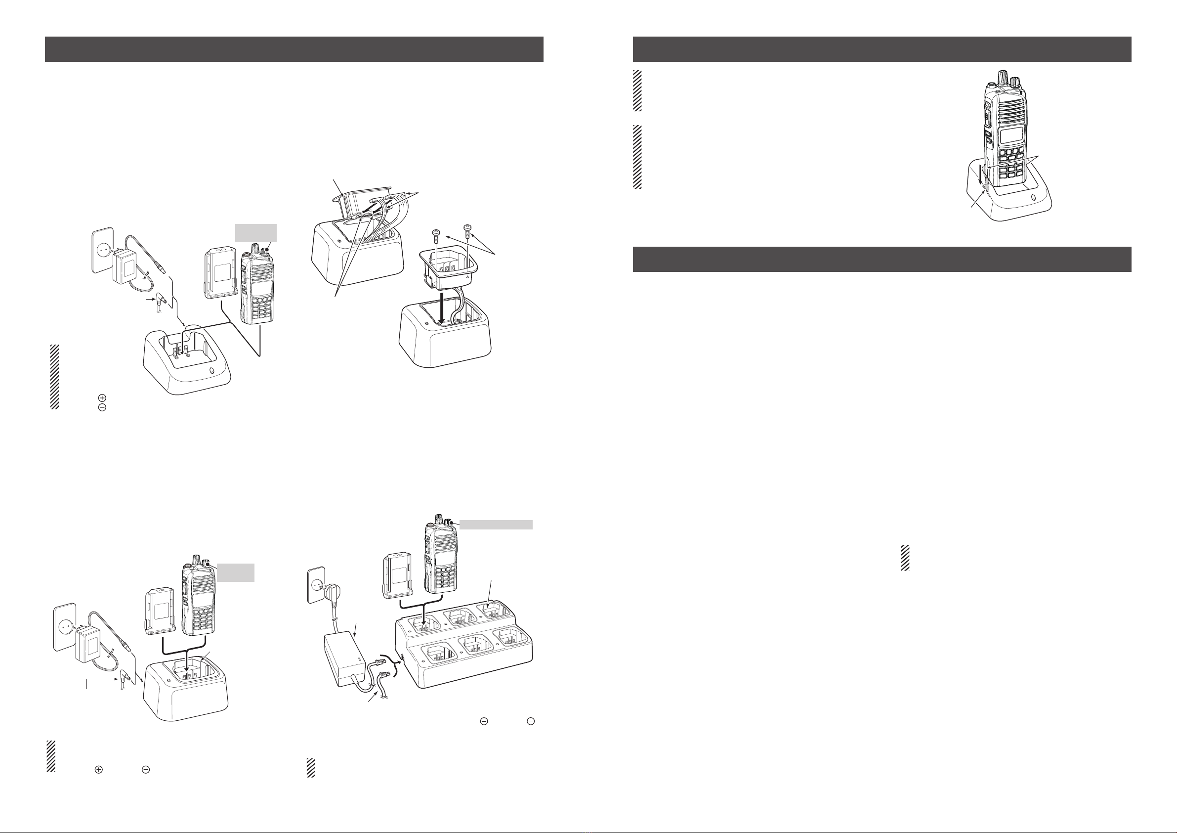
DRapid charging with the BC-119N+AD-106
You can rapidly charges the Li-ion battery pack with the
optional BC-119N.
Charging time: Approximately 3.5 hours for the BP-232WP
The following items are additionally required.
• AD-106 charger adapter (purchase separately)
• A power adapter (may be supplied with BC-119N,
depending on the charger version) or the OPC-515L/
CP-23L DC power cable.
(A different type, or no
power adapter is sup-
plied, depending on the
charger’s version.)
Optional OPC-515L* (for a
13.8 V power source) or
CP-23L (for a 12 V cigarette
lighter socket) can be used
instead of the power adapter.
CAUTION: NEVER connect the OPC-
515L to a power source using reverse
polarity. This will ruin the battery charger.
White line: Black line:
*
Battery
pack
AD-106 charger
adapter is
in the BC-119N.
Transceiver
Tu rn OFF
the power
DCharging with the BC-160/BC-171
You can rapidly charge the Li-ion battery pack with the
BC-160, or regularly charge the pack with the BC-171.
•Charging time
BC-160: Approximately 3.5 hours for the BP-232WP
BC-171: Approximately 11.5 hours for the BP-232WP
The following items are additionally required:
• A power adapter (may be supplied with the charger,
depending on the charger version) or the OPC-515L/
CP-23L DC power cable.
(A different type, or no power adapter is supplied,
depending on the charger’s version.)
Battery
pack
T
Tu rn power
OFF
OPC-515L* (for a
V power source) or
(for a 12 V cigarette
socket) can be used
wer adapter.
CAUTION: NEVER
connect the OPC-
515L to a power
source using reverse
polarity. This will ruin
the battery charger.
White line:
Black line :
*
DAD-106 installation
You must install the AD-106 charger adapter into the
BC-119N desktop charger or BC-121N multi-charger
before charging any batteries.
q Connect the AD-106 and the BC-119N/BC-121N.
wInstall the AD-106 into the holder space of the BC-119N/
BC-121N with the supplied screws.
Screws
with the
adapter
Plugs
Sockets
ws
DRapid charging with the BC-121N+AD-106
You can charge up to 6 battery packs with the optional
BC-121N.
Charging time: Approximately 3.5 hours for the BP-232WP
The following items are additionally required.
(purchase separately)
• Six AD-106 charger adapters
• BC-157S power adapter or the OPC-656 DC power cable
Transceiver
Battery
pack
AD-106 charger
adapters are installed
in each slot.
Turn OFF the power
Power adapter
*Polarity of the OPC-656
Red line: Black line:
OPC-656* DC power cable
Connect to a 13.8 V, 7 A (min.)
power supply
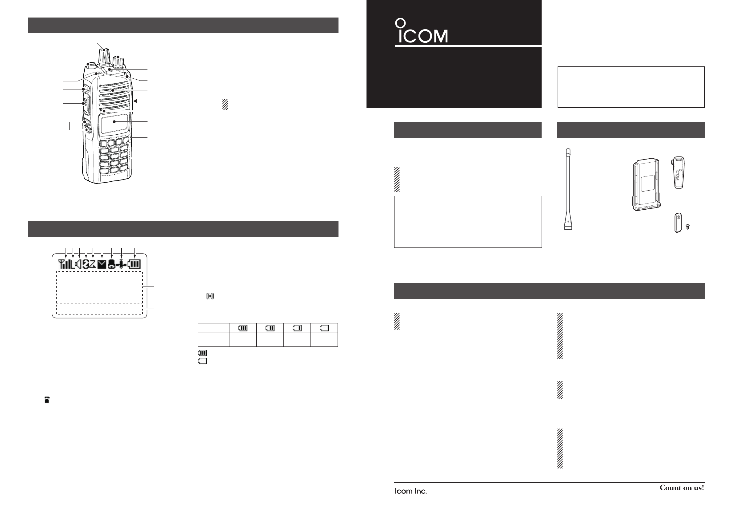
DBATTERY PACKS
• BP-232WP li-ion battery pack
Voltage: 7.4 V, Capacity: 2250 mAh (min.) 2300 mAh (typical)
Battery life: (Digital mode) Approximately 14.5 hours
(Analog mode) Approximately 13 hours
When the power save function is set to “Short,” and the operating
periods are calculated under the following conditions:
TX:RX:standby = 5:5:90
• BP-240/BP-261 battery case
BP-240: For AAA (LR03) ×6 alkaline
BP-261: For AA (LR6) ×6 alkaline
BP-240 and BP-261 have IPX4 waterproof protection. When in
use, the transceiver’s waterproof rating meets IPX4.
DDC CABLES
• CP-23L cigarette lighter cable
Used when charging battery packs through a 12 V cigarette
lighter socket. For use with the BC-119N/BC-160 chargers.
• OPC-515L/OPC-656 dc power cables
Used when charging battery packs using a 13.8 V DC power
source instead of the power adapter.
OPC-515L: For the BC-119N/BC-160
OPC-656: For the BC-121N/BC-197
DCHARGERS
• BC-119N desktop charger + AD-106 charger adapter
+ BC-145S power adapter
For rapidly charging of battery packs.
A power adapter may be supplied, depending on the charger’s version.
Charging time: Approximately 3.5 hours for the BP-232WP.
• BC-121N multi-charger + AD-106 charger adapter (6 pcs.)
+ BC-157S power adapter
For rapidly charging of up to 6 battery packs simultaneously.
Six AD-106s are required.
A power adapter or a DC power source must be purchased separately.
Charging time: Approximately 3.5 hours for the BP-232WP.
• BC-197 multi-charger + AD-122 charger adapter (6 pcs.)
+ BC-157S ac adapter
For rapidly charging of up to 6 battery packs simultaneously.
Six AD-122s are required.
A power adapter or a DC power source must be purchased separately.
Charging time: Approximately 3.5 hours for the BP-232WP.
• BC-160 desktop charger + BC-145S power adapter
For rapidly charging of battery packs.
A power adapter may be supplied, depending on the charger’s version.
Charging time: Approximately 3.5 hours for the BP-232WP.
• BC-171 desktop charger + BC-147S power adapter
For regularly charging of battery packs.
A power adapter may be supplied, depending on the charger’s version.
Charging time:
Approximately
11.5 hours for the BP-232WP.
DBELT CLIPS
• MB-93 swivel belt clip
• MB-94/MB-94R belt clip
Alligator-type belt clip.
• MB-96N/MB-96F leather belt hanger
DANTENNAS
• FA-SC56VS/FA-SC57VS/FA-SC73US stubby antennas
Shorter VHF or UHF antennas.
FA-SC56VS: 150–162 MHz FA-SC57VS: 160–174 MHz
FA-SC73US: 450–490 MHz
• FA-SC25V/FA-SC55V/FA-SC03U
FA-SC25U/FA-SC57U/FA-SC72U flexible antennas
VHF or UHF antennas.
FA-SC25V: 136–150 MHz FA-SC55V: 150–174 MHz
FA-SC03U: 380–430 MHz FA-SC25U: 400–430 MHz
FA-SC57U: 430–470 MHz FA-SC72U: 470–520 MHz
• FA-SC61VC/FA-SC61UC cut antennas
FA-SC61VC: 136–174 MHz FA-SC61UC: 380–520 MHz
• FA-SC62V/FA-SC63V high gain antennas
FA-SC62V: 150–160 MHz FA-SC63V: 155–165 MHz
DOTHERS
• AD-118 acc adapter
Allows you to connect an accessory which uses a HIROSE
plug. See the instruction sheet of the AD-118 for details of the
recommended accessories.
CAUTION: The AD-118 does not have any waterproof
protection. When it is connected, NEVER expose the adaptor
and the transceiver to rain, snow or any liquids.
• HM-184/HM-184H speaker microphone
Rugged type speaker microphone.
The HM-184 and HM-184H meet IP67 requirements for
waterproof protection.
• MB-130 vehicle charger bracket
Vehicle mounting bracket for the BC-160 battery charger.
OPTIONS
BATTERY CHARGING (Continued)
IMPORTANT: Battery charging caution
Ensure the guide tabs on the battery pack are correctly
aligned with the guide rails inside the charger adapter.
This illustration is for the BC-160.
CAUTION:
When using the OPC-656 DC power cable
NEVER reverse the polarity when connecting the
OPC-656 to a power source. This will ruin the battery
charger.
OPC-656: Red line: +,Black line: _
Some options may not be available in some countries. Please ask your dealer
for details.
Tabs
Guide rail
NOTE: For the instructions on the BC-197 multi-charger,
see the instruction manual supplied with the charger.