Avenue Einstein 11/B | B-1348 Louvain-la-Neuve (Belgium) | T + 32 10 45 41 02 | F + 32 10 45 04 61 | info@icomsdetections.com
ICOMS DETECTIONS SA
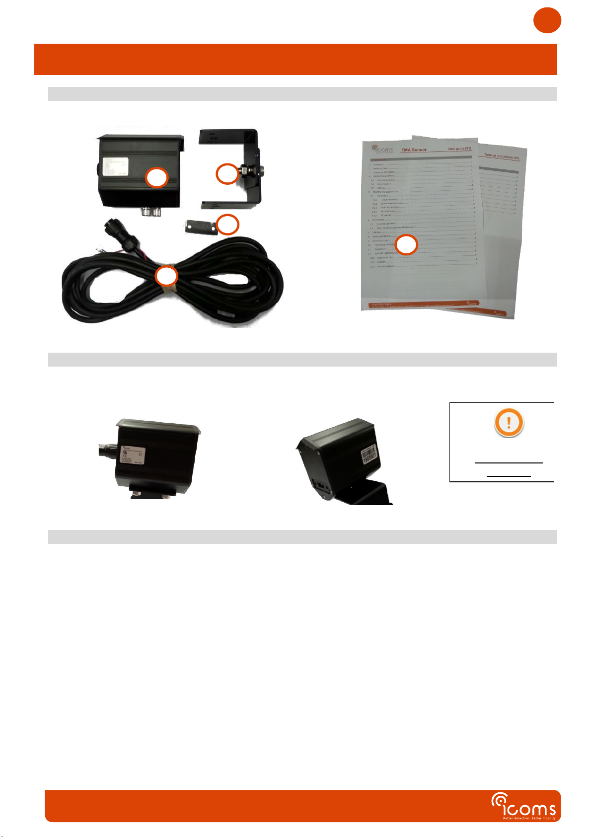
TMA Sensor
User guide
TMA-011 configuration
Tune up procedure
CONTENTS
CONTENTS ...........................................................................................................................................................1
ILLUSTRATIONS TABLE..........................................................................................................................................2
1DELIVERY..........................................................................................................................................................4
2LABELS LOCATION ...............................................................................................................................................4
2.1 IDENTIFICATION LABEL ................................................................................................................................................... 4
2.2 SERIAL NUMBER ........................................................................................................................................................... 4
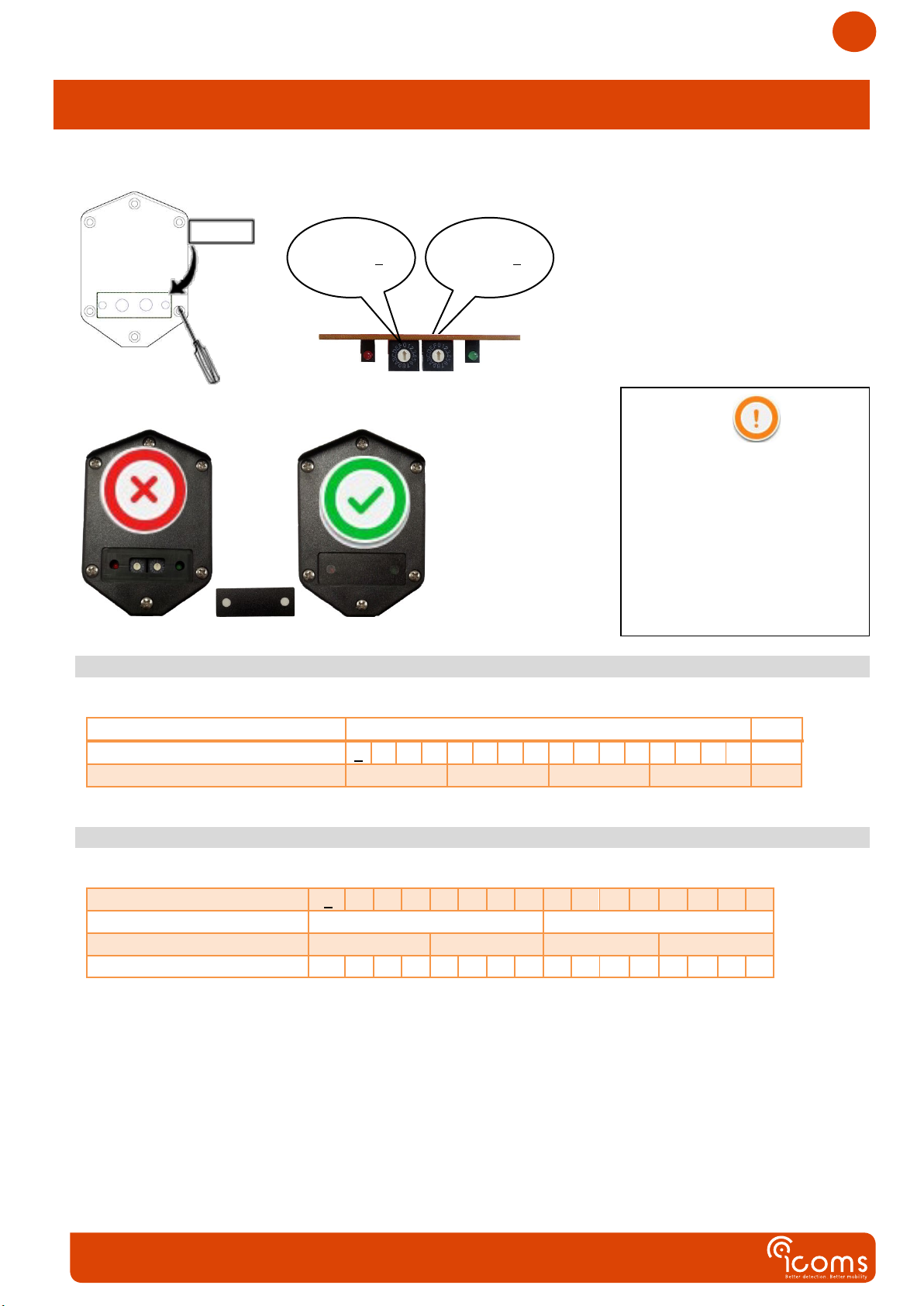
3SETTINGS..........................................................................................................................................................4
SAFETY PRECAUTIONS..........................................................................................................................................5
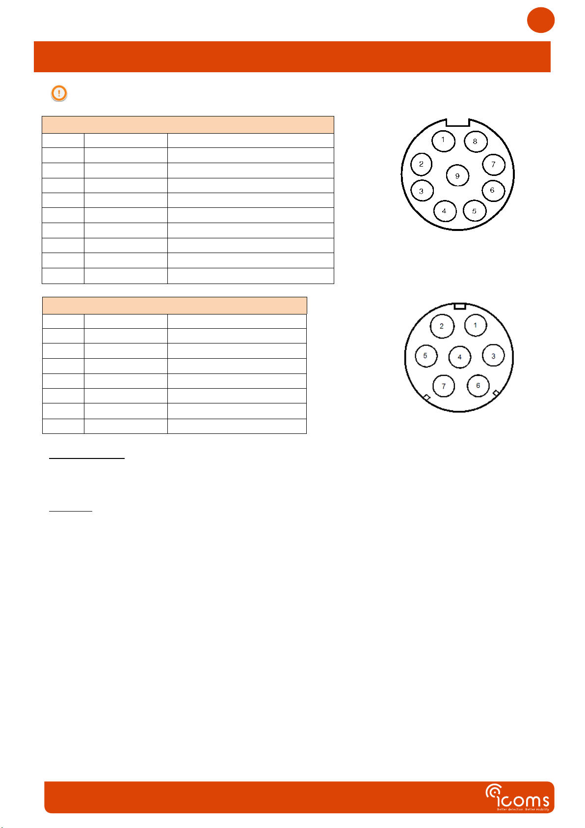
CABLING ..............................................................................................................................................................6
DESCRIPTION OF PARAMETERS ............................................................................................................................7
1SELF-MONITORING..............................................................................................................................................7
2RF CHANNEL......................................................................................................................................................7
3DETECTION DISTANCE ..........................................................................................................................................7
4DETECTION DIRECTION .........................................................................................................................................7
TMA-011 – SET-UP & INSTALLATION .....................................................................................................................8
1ENCODER 1 .......................................................................................................................................................8
2ENCODER 2 .......................................................................................................................................................8
RADAR BOOT UP..................................................................................................................................................9
1TEST MODE .......................................................................................................................................................9
2NORMAL OPERATION...........................................................................................................................................9
LED INDICATOR....................................................................................................................................................9
1IN NORMAL OPERATION .......................................................................................................................................9
2WHEN THE SELF-MONITORING DETECTS AN ERROR ......................................................................................................9
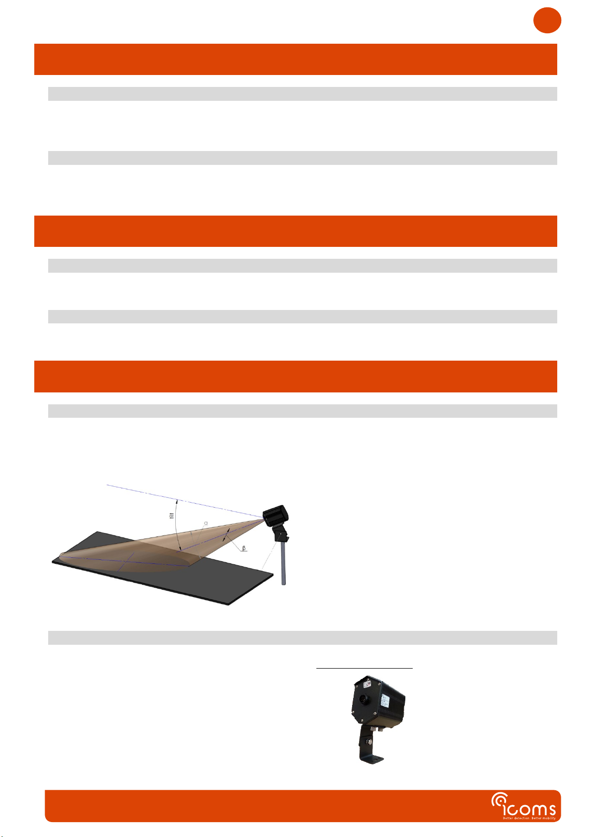
INSTALLATION GUIDE...........................................................................................................................................9
1GENERAL ..........................................................................................................................................................9
2ASSEMBLY AND MOUNTING...................................................................................................................................9