ICON COBALT Pro 101674 User manual

COBALT Pro™ Wall Sensor Retrot Kit for
Concealed Flush Valve Installation Instructions
I-CON Systems, Inc., for product support call 1-866-730-7192 or visit us online at support.i-con.com
One or more products contained herein are protected by U.S. Patent with other undergoing the patent process www.i-con.com/patents
Part No. 101674
Flat Head Screwdriver
Phillips Screwdriver
T15H Screwdriver
Smooth Jaw
Wrench
page 1
Rev 080323
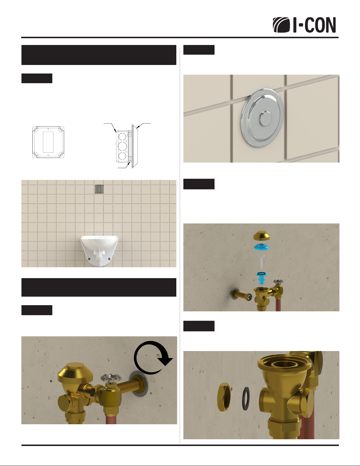
• Sensor Cap Assembly
• ProLAST® T-Seal
• Actuator Opening Cover
• Wall Sensor
• Power & Interface Module
KIT INCLUDES
TOOLS NEEDED
Strap Wrench
• All plumbing should be installed according to applicable state
and local codes and regulaons.
• Before installaon of the I-CON ush valve, ensure the water
closet or urinal xture, drain line and water supply line are
properly installed.
• Water supply lines must be sized to allow for appropriate
water ow for each xture.
• Flush all water supply lines of any debris before making
connecons.
• Do not use pipe sealant or plumbing grease on any
components or couplings, with the excepon of the control stop
inlet.
• A smooth jaw or strap wrench should be used for installaon
to prevent damage to the nish of the I-CON ush valve and
components.
The I-CON ush valve is designed to operate at water pressures
ranging from 15 to 100psi (103 to 689kPa). The xture type
determines the minimum pressure required for the valve.
Most low-consumpon water closets are designed to operate
with a minimum owing water pressure of 25psi (172kPa).
Many building codes and the ASME A112.19.2 standard state
maximum stac water pressure as 80 psi.
I-CON Systems, Inc. (I-CON) warrants that its commercial
manufactured products are made of rst-class materials, are
free from defects, and are made to withstand normal use when
installed properly. Products have the following warranty periods:
3 years for COBALT®, COBALT Pro™, and COBALT Connect™
faucets and ush valves and I-CON EDGE® gateways. 1 year for
all other products and decorave nishes. The warranty period
begins on the date of purchase.
Products should be sent to I-CON at the customer’s expense.
I-CON will take a reasonable amount of me to determine
if the product is defecve and whether it will be repaired or
replaced. During the warranty period, items will either be
(1) repaired at no charge using new replacement parts or (2)
replaced with either a new similar product or one manufactured
from new or serviceable used parts that are, at minimum, a
funconal equivalent to the original. The course of acon will
be determined at I-CON’s discreon. Replacement products that
are installed according to the instrucons provided by I-CON
will assume the remaining warranty of the original product. The
limited warranty is only applicable to the product’s materials
and workmanship. No claims for labor, transportaon, or other
incidental or consequenal costs will be allowed. No extended
warranes are available. THE SOLE AND EXCLUSIVE REMEDY
FOR ANY DEFECTIVE PRODUCT IS LIMITED TO REPAIRING OR
REPLACING THE DEFECTIVE PRODUCT. Before installing and
using products, the purchaser is responsible for determining the
products’ suitability and assumes all risks and liabilies related
to the product.
This warranty only applies to persons and organizaons that
purchase I-CON products directly from I-CON or an authorized
I-CON representave for the purpose of resale. This warranty
does not apply to the life of baeries or other consumables.
PRIOR TO INSTALLATION
LIMITED WARRANTY

COBALT Pro™ Wall Sensor Retrot Kit for
Concealed Flush Valve Installation Instructions
I-CON Systems, Inc., for product support call 1-866-730-7192 or visit us online at support.i-con.com
One or more products contained herein are protected by U.S. Patent with other undergoing the patent process www.i-con.com/patents
Part No. 101674
page 2
Rev 080323
ELECTRICAL BOX INSTALLATION
Step 1
Install 2-gang electrical box (4” x 4” x 2-1/2”). The locaon will
vary based on the rough-in. Refer to the rough-in drawings for
specic mounng locaon. Use a GFCI plaster ring.
4X4 JUNCTION
BOX
GFCI PLASTER RING
I-CON IR PLATE
AN I-CON IR PLATE MOUNTS TO
GFCI JUNCTION BOX COVERS
EXISTING COMPONENT REMOVAL
Step 1
Turn adjustment wheel CLOCKWISE to close control stop.
Step 2
Acvate ush valve to relieve water pressure.
Step 3
Use strap wrench to remove ush valve cap. Remove actuator
assembly and all inner components. Inner components commonly
include a diaphragm, trip mechanism, and plasc internal cap.
Step 4
Install actuator cover.

COBALT Pro™ Wall Sensor Retrot Kit for
Concealed Flush Valve Installation Instructions
I-CON Systems, Inc., for product support call 1-866-730-7192 or visit us online at support.i-con.com
One or more products contained herein are protected by U.S. Patent with other undergoing the patent process www.i-con.com/patents
Part No. 101674
page 3
Rev 080323
ProLAST®T-SEAL & FLUSH VALVE CAP
ASSEMBLY INSTALLATION
Step 1
Insert ProLAST® T-Seal into ush valve body.
Step 2
Place square-prole O-ring into groove on boom of ush valve
cap assembly. Place ush valve cap assembly onto ush valve
body.
Step 3
Tighten locking ring by hand to ush valve body.
WALL SENSOR INSTALLATION - INSTALLATION
WITH ELECTRICAL BOX
Step 1
Loosen set screw on plate. Remove cover by pulling out, then up.
Step 2
Feed control module cable through juncon box knock-out.
Aach control module to juncon box with provided screws.

COBALT Pro™ Wall Sensor Retrot Kit for
Concealed Flush Valve Installation Instructions
I-CON Systems, Inc., for product support call 1-866-730-7192 or visit us online at support.i-con.com
One or more products contained herein are protected by U.S. Patent with other undergoing the patent process www.i-con.com/patents
Part No. 101674
page 4
Rev 080323
Step 3
Reaach and secure cover with set screw.
WALL SENSOR INSTALLATION - INSTALLATION
WITHOUT ELECTRICAL BOX
Step 1
Drill 1-1/2” hole through wall. The locaon will vary based on the
exisng ush valve installaon. Typically installed 21” about the
xture on the centerline.
Step 2
Drill openings for wall anchors using 3/16” drill. See dimensional
drawing. Insert wall anchors.
3
16
"
5
3
16
"
5
11
2
"
38
15
8
"
41
15
8
"
41
31
4
"
83
COMMERCIAL CUTSHEET
TO CHANGE
ANNOTATION SHOULD BE \\i-consystems.int\Operations\CAD Drawings\TEMPLATES\ANSI-CUTSHEET-TEMPLATE.sldstd
•
SET NORMAL LINE THICKNESS TO .004
•
SET THIN LINE THICKNESS TO .002
•
ADJUST SHEET SCALE TO FILL PAGE
•
SET FRACTIONAL DISPLAY TO VERTICAL
•
SET BENT LEADER LENGTH TO 0.1" IN ANNOTATION AND DIMENSIONING
•
TEXT SHOULD BE ALL CAPS
•
DUAL DIMENSION MEASUREMENT (MILLIMETER) SHOULD MATCH THE FRACTIONAL DISPLAY (INCHES)
•
TEMPLATE INFORMATION
PAGE SIZE 3"x3"
•
CENTURY GOTHIC SIZE 8 FONT
•
ONE-TIME SYSTEM SETTING CHANGE
DIMENSIONS NON-IMPORTED (DRIVEN) AND DIMENSIONS (DANGLING) SET TO BLACK
•
SKETCH (INACTIVE) AND SKETCH (UNDEFINED) SET TO BLACK
•
SET PDF EXPORT LINES AND SHADED EDGES TO HIGH QUALITY
•
SET PDF EXPORT SHADED/DRAFT GEOMETRY AND SHARPENED OLE DPI TO 600
•
PARAMETERS TO MEET
INDICATE A CENTERLINE OF FIXTURE
•
INDICATE A CENTERLINE OF SUPPLY FOR CONCEALED SYSTEMS
•
INDICATE A CENTERLINE OF WALL SENSOR WHEN APPLICABLE
•
Step 3
Loosen set screw on face plate. Remove cover by pulling out,
then up.

COBALT Pro™ Wall Sensor Retrot Kit for
Concealed Flush Valve Installation Instructions
I-CON Systems, Inc., for product support call 1-866-730-7192 or visit us online at support.i-con.com
One or more products contained herein are protected by U.S. Patent with other undergoing the patent process www.i-con.com/patents
Part No. 101674
page 5
Rev 080323
Step 4
Feed control module cable through 1-1/2” opening.
Aach control module to wall with provided screws.
Step 5
Reaach and secure face plate with set screw.
INTERFACE MODULE INSTALLATION
Step 1
Open interface module. Mount to at surface in chase. Use wall
anchors and screws provided. NOTE: The solenoid cable is 48”
long and has 18” of conduit. Ensure the solenoid cable can be
easily plugged into the interface box.
Step 2
Connect cables for pressure and temperature sensor, control
module, solenoid, and power.
Step 3
Plug in transformer. Power on interface module using external
power switch. Close interface module.

COBALT Pro™ Wall Sensor Retrot Kit for
Concealed Flush Valve Installation Instructions
I-CON Systems, Inc., for product support call 1-866-730-7192 or visit us online at support.i-con.com
One or more products contained herein are protected by U.S. Patent with other undergoing the patent process www.i-con.com/patents
Part No. 101674
page 6
Rev 080323
ADJUSTING CONTROL STOP
Step 1
Turn adjustment wheel COUNTERCLOCKWISE 1/2 turn from
closed posion. Acvate ush valve.
Step 2
To adjust ush valve, turn adjustment wheel in small increments.
Acvate ush valve aer each adjustment. The proper ow rate
should completely cleanse xture without splashing water
outside of xture.
NOTE: The ow from the valve must never exceed the ow
capacity of the xture. If a valve failure should occur, the xture
must be able to accommodate a connuous ow from the valve.
CONTROL MODULE AND INTERFACE SETUP
NOTE: When powered and face plate is removed, control
module automacally enters maintenance mode. While
maintenance mode is acve, a solid green light indicates that
a user is detected. Control module exits maintenance mode
when face plate is replaced or aer 30 minutes. To re-enter
maintenance mode, press any quick acon buon.
QUICK ACTION BUTTON DIAGRAM
Full FlushHalf Flush
Full
Flush
Count
Reset

COBALT Pro™ Wall Sensor Retrot Kit for
Concealed Flush Valve Installation Instructions
I-CON Systems, Inc., for product support call 1-866-730-7192 or visit us online at support.i-con.com
One or more products contained herein are protected by U.S. Patent with other undergoing the patent process www.i-con.com/patents
Part No. 101674
page 7
Rev 080323
AUTO-RANGE
To set range automacally, press and hold the auto range quick
acon buon for 3 seconds. Place target at desired detecon
range within 5 seconds. Green light blinks every second during
countdown. Sensor will lock on to target, indicated by solid green
light. Green light will blink to conrm range is set.
NOTE: Test range with targets of various colors and textures for
accuracy. Ensure foreign objects, such as stall doors and mirrors,
are not detected.
PROFILE
To view current prole, press and release prole quick acon
buon. Current prole number is displayed through LED
illuminaons and the digital display. To change prole, press
and release prole quick acon buon again. Connue to press
and release prole quick acon buon unl desired prole is
displayed. Press and hold prole quick acon buon for 3
seconds to set prole. Blue lights will ash to indicate prole
was saved.
Display Prole Flush Volume
P1 - Red & Blue Prole 1 10% Water Savings
P2 - Blue Prole 2 5% Water Savings
P3 - Green & Blue Prole 3 Standard Flush Volume
ACTIVATE
Acvates a full ush of the ush valve.
ACTIVATION COUNT RESET
The acvaon count can be monitored by using the onboard
display. It will display AC (Acvaon Count) followed by the
number of acvaons since the last rebuild. A red LED blinking
alarm will begin once the acvaon count has surpassed 250,000
cycles. At this me, it is recommended to rebuild the valve. To
reset this alarm, press and hold the acvaon count reset for
5 seconds. The red LED will ash indicang the count has been
reset to 0.
INSTALLATION COMPLETE

COBALT Pro™ Wall Sensor Retrot Kit for
Exposed Flush Valve Installation Instructions
I-CON Systems, Inc., for product support call 1-866-730-7192 or visit us online at support.i-con.com
One or more products contained herein are protected by U.S. Patent with other undergoing the patent process www.i-con.com/patents
Part No. 101675
page 8
Rev 080323
PROGRAMMING QUICK REFERENCE
When adjustment LEDs are illuminated, their corresponding values appear on the display. Make adjustments as necessary.
See standard operaons guide for more informaon.
Range adjusts the maximum range used to detect a user. The range can be adjusted from 6-54 inches.
Exit adjusts the amount of me an object must not be detected before the valve considers the user to have exited.
The range can be adjusted from 0-15 seconds.
Run adjusts the water volume savings in percent.
Redetect adjusts the amount of me a user must be out of range before another user can be detected.
The range can be adjusted from 0-60 seconds.
CARE OF CHROME PLATED SURFACES
DO NOT use commercial cleaning compounds to clean ush valve. Abrasive or chemical cleaners may dull luster and aack nishes.
Use mild soap and water and then dry with a clean nonabrasive cloth or towel. A microber cloth is recommended. Protect ush
valve from any splaering when cleaning the oor, le, or xtures. DO NOT USE ACID OR ALCOHOL BASED CLEANERS.
Table of contents
Other ICON Plumbing Product manuals
Popular Plumbing Product manuals by other brands

Elkay
Elkay ESRC8 1F Installation, care & use manual

Gessi
Gessi 39821 Maintenance manual

Hans Grohe
Hans Grohe Focus 100 Series Instructions for use/assembly instructions

JETStream
JETStream VERSABOOM QSG-201 quick start guide

Balmani
Balmani Napoli installation guide

Kohler
Kohler K-9053, K-9054 Homeowner's guide