ICP DAS USA DN-8368MB User manual

DN-8368MB
User Manual
(Version 1.0)
For Mitsubishi J2 series Servo Driver
http://www.icpdas.com DN-8368MB User Manual V 1.0 1

Warranty
All products manufactured by ICPDAS Inc. are warranted against
defective materials for a period of one year from the date of delivery to the
original purchaser.
Warning
ICPDAS Inc. assumes no liability for damages consequent to the use of
this product. ICPDAS Inc. reserves the right to change this manual at any
time without notice. The information furnished by ICPDAS Inc. is believed to
be accurate and reliable. However, no responsibility is assumed by ICPDAS
Inc. for its use, or for any infringements of patents or other rights of third
parties resulting from its use.
Copyright
Copyright 1997-2009 by ICPDAS Inc., LTD. All rights reserved
worldwide.
Trademark
The names used for identification only maybe registered trademarks of
their respective companies.
License
The user can use, modify and backup this software on a single machine.
The user may not reproduce, transfer or distribute this software, or any
copy, in whole or in part.
http://www.icpdas.com DN-8368MB User Manual V 1.0 2

目錄
1 ENGLISH VERSION.........................................................4
...............................................................................41.1 Board Layout for DN-8368MB
..............................................................................................51.2 I/O Signal connector .....................................................111.3 I/O connector for servo motor of Mitsubishi
...............................................................................151.4 Jumper and Switch Settings
...................................................................................................201.5 LED Description
2 繁體中文版 .......................................................................21
...................................................................................................212.1 DN-8368MB配置
..............................................................................................................222.2訊號連接器 ........................................................................................282.3伺服馬達專用訊號連接器 .......................................................................................322.4 Jumper與開關調撥設定
2.5 LED 功能描述........................................................................................................37
http://www.icpdas.com DN-8368MB User Manual V 1.0 3

1 English version
The DN-8368MB is a terminal board connecting between Mitsubishi J2S series
servo driver (with pulse train input amplifier) and ICP DAS PISO-PS600,
PISO-VS600 or PMDK motion controller card. Please do not use it to connect any
other servo driver or cards. Moreover, it also includes 3-axis I/O signals. We expect
to reduce the wiring between Mitsubishi J2S series servo driver and the motion
controller card. This manual describes signals and operation instructions of
DN-8368MB; the content is divided into 5 parts. 1. Board layout, 2. I/O Signal
connectors, 3. Signal connectors for Mitsubishi J2S series servo amplifier, 4.
Jumper and switch setting, 5. LED function describes, etc.
1.1 Board Layout for DN-8368MB
Dimension and Placement
Fig. 1-1 Board layout for the DN-8368MB
http://www.icpdas.com DN-8368MB User Manual V 1.0 4

1.2 I/O Signal connector
Assuring reliable connections is one of the most important tasks when sending or
receiving data from your application systems. This chapter will introduce I/O
connector (for general purposes) on DN-8368MB and machine platform specific I/O
connector. Users can find various signal usage and meanings in this section.
CON1
The I/O connector on DN-8368MB is a 68-pin SCSI II connector that enables you to
connect to the sensors and motor drivers to the motion card. Please note: there
are two groups of connectors (CN1A/ CN1B) on the main card; therefore, the same
signal may have a different name on each sub board. Please refer to Table 1-1,
Table 1-2for your reference.
http://www.icpdas.com DN-8368MB User Manual V 1.0 5

http://www.icpdas.com DN-8368MB User Manual V 1.0 6
Table 1-1 CN1A(be close the PCB)
No. Name I/O Function Axis No
.Name I/O Function Axis
1 AOUT0 O Analog Output 35 AIN0 IAnalog Input
2 AOUT1 O Analog Output 36 AIN1 IAnalog Input
3 AOUT2 O Analog Output 37 AIN2 IAnalog Input
4 AGND - Analog Ground 38 AGND - Analog Ground
5 DGND - Digital Ground 39 ERC0 OError Counter Clear
6 LTC0 I Position Latch 40 SVON0 OServo On
7 EA0 I Encoder A-Phase 41 RDY0 IServo Ready
8 EB0 I Encoder B-Phase 42 INP0 IServo In-Position
9 EZ0 I Encoder Z-Phase 43 ALM0 IServo Alarm
10 CW0 O Clockwise pulse 44 SLD0 ISlow Down
11 CCW0 O Counter-Clockwise
pulse 45 ORG0 IOrigin Signal
12 CMP0 O Compare Trigger 46 MEL0 IMinus End Limit
13 EMG I Emergency Stop 47 PEL0 IPositive End Limit
14 ALMRST0 O Servo Alarm Reset 48 DGND - Digital Ground
15 DGND - Digital Ground 49 ERC1 OError Counter Clear
16 LTC1 I Position Latch 50 SVON1 OServo On
17 EA1 I Encoder A-Phase 51 RDY1 IServo Ready
18 EB1 I Encoder B-Phase 52 INP1 IServo In-Position
19 EZ1 I Encoder Z-Phase 53 ALM1 IServo Alarm
20 CW1 O Clockwise pulse 54 SLD1 ISlow Down
21 CCW1 O Counter-Clockwise
pulse 55 ORG1 IOrigin Signal
22 CMP1 O Compare Trigger 56 MEL1 IMinus End Limit
23 GDO1 O Generic Digital Output 57 PEL1 IPositive End Limit
24 ALMRST1 O Servo Alarm Reset 58 DGND - Digital Ground
25 DGND - Digital Ground 59 ERC2 OError Counter Clear
26 LTC2 I Position Latch 60 SVON2 OServo On
27 EA2 I Encoder A-Phase 61 RDY2 IServo Ready
28 EB2 I Encoder B-Phase 62 INP2 IServo In-Position
29 EZ2 I Encoder Z-Phase 63 ALM2 IServo Alarm
30 CW2 O Clockwise pulse 64 SLD2 ISlow Down
31 CCW2 O Counter-Clockwise
pulse 65 ORG2 IOrigin Signal
32 CMP2 O Compare Trigger 66 MEL2 IMinus End Limit
33 DGND - Digital Ground 67 PEL2 IPositive End Limit
34 ALMRST2 O Servo Alarm Reset 68 VCC - 5V Digital Power
from Bus

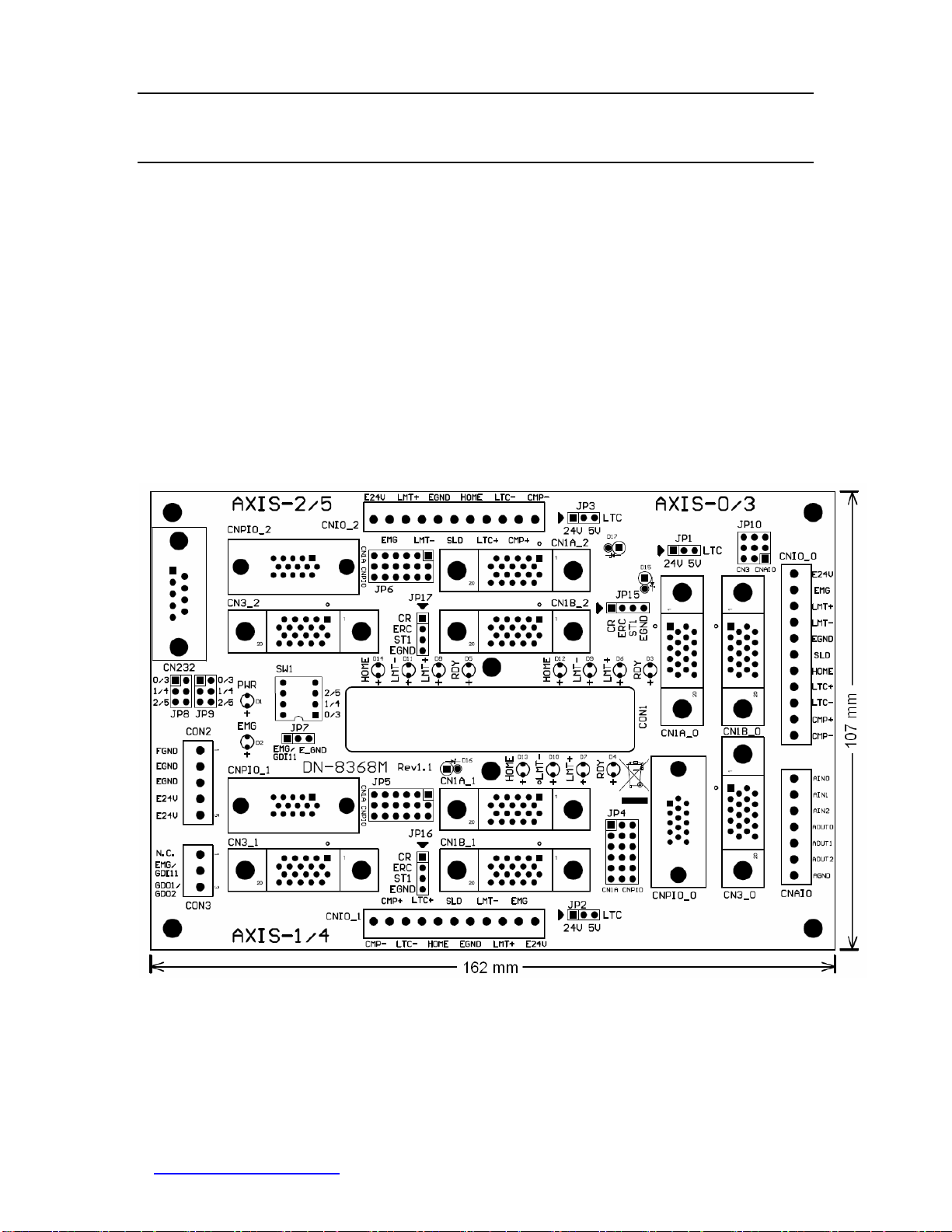
http://www.icpdas.com DN-8368MB User Manual V 1.0 7
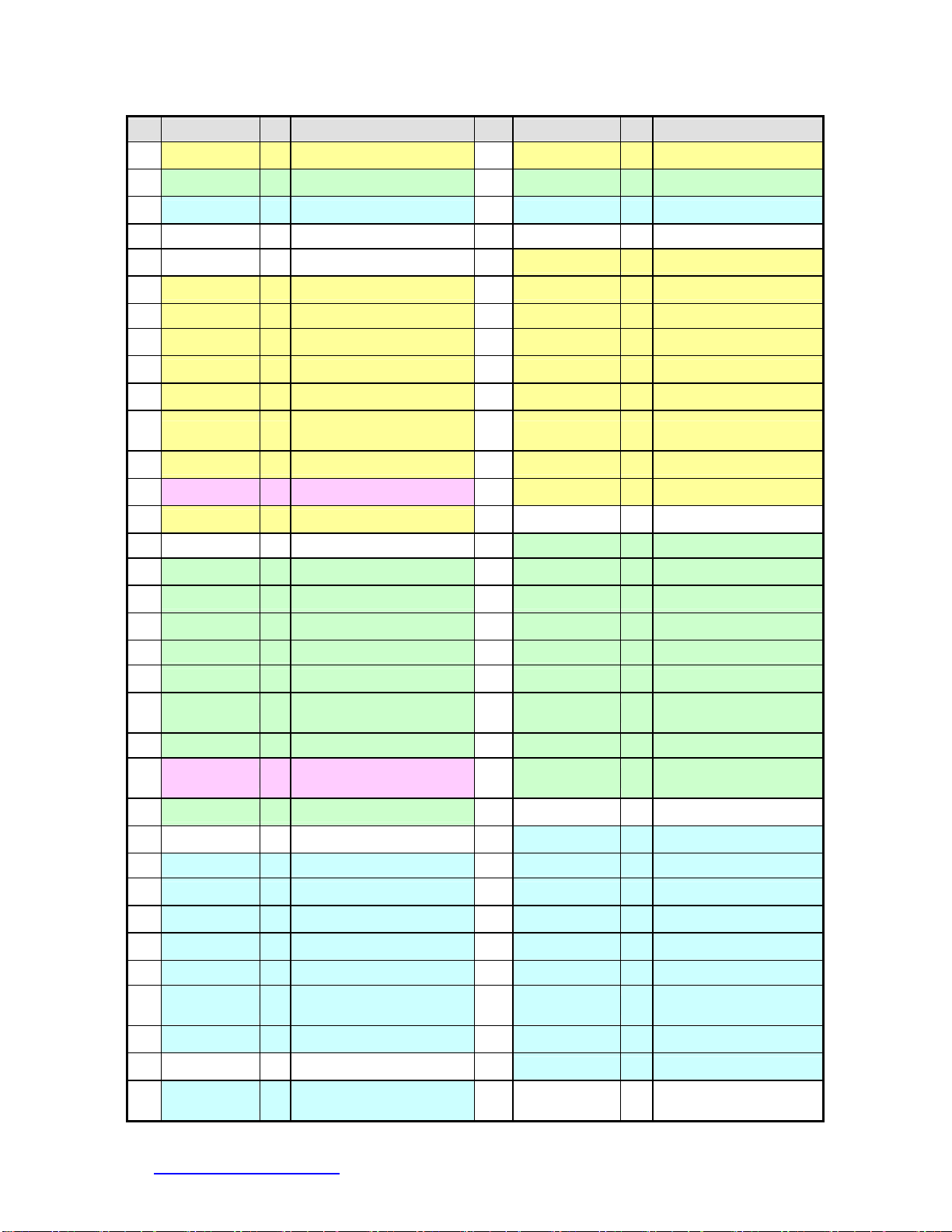
Table 1-2 CN1B (be distances from PCB)
No. Name I/O Function Axis No. Name I/O Function Axis
1 AOUT3 O Analog Output 35 AIN3 IAnalog Input
2 AOUT4 O Analog Output 36 AIN4 IAnalog Input
3 AOUT5 O Analog Output 37 AIN5 IAnalog Input
4 AGND - Analog Ground 38 AGND - Analog Ground
5 DGND - Digital Ground 39 ERC3 OError Counter Clear
6 LTC3 I Position Latch 40 SVON3 OServo On
7 EA3 I Encoder A-Phase 41 RDY3 IServo Ready
8 EB3 I Encoder B-Phase 42 INP3 IServo In-Position
9 EZ3 I Encoder Z-Phase 43 ALM3 IServo Alarm
10 CW3 O Clockwise pulse 44 SLD3 ISlow Down
11 CCW3 O Counter-Clockwise
pulse 45 ORG3 IOrigin Signal
12 CMP3 O Compare Trigger 46 MEL3 IMinus End Limit
13 GDI11 I Generic Digital Input 47 PEL3 IPositive End Limit
14 ALMRST3 O Servo Alarm Reset 48 DGND - Digital Ground
15 DGND - Digital Ground 49 ERC4 OError Counter Clear
16 LTC4 I Position Latch 50 SVON4 OServo On
17 EA4 I Encoder A-Phase 51 RDY4 IServo Ready
18 EB4 I Encoder B-Phase 52 INP4 IServo In-Position
19 EZ4 I Encoder Z-Phase 53 ALM4 IServo Alarm
20 CW4 O Clockwise pulse 54 SLD4 ISlow Down
21 CCW4 O Counter-Clockwise
pulse 55 ORG4 IOrigin Signal
22 CMP4 O Compare Trigger 56 MEL4 IMinus End Limit
23 GDO2 O Generic Digital
Output 57 PEL4 IPositive End Limit
24 ALMRST4 O Servo Alarm Reset 58 DGND - Digital Ground
25 DGND - Digital Ground 59 ERC5 OError Counter Clear
26 LTC5 I Position Latch 60 SVON5 OServo On
27 EA5 I Encoder A-Phase 61 RDY5 IServo Ready
28 EB5 I Encoder B-Phase 62 INP5 IServo In-Position
29 EZ5 I Encoder Z-Phase 63 ALM5 IServo Alarm
30 CW5 O Clockwise pulse 64 SLD5 ISlow Down
31 CCW5 O Counter-Clockwise
pulse 65 ORG5 IOrigin Signal
32 CMP5 O Compare Trigger 66 MEL5 IMinus End Limit
33 DGND - Digital Ground 67 PEL5 IPositive End Limit
34 ALMRST5 O Servo Alarm Reset 68 VCC - 5V Digital Power
from Bus

CON2
The connectors CON2 are a 5-pin connector for external Power supply (24V input).
Table 1-3 shows its I/O connector signal description.
Table 1-3
Pin NO Pin Define Function description
1 FGND Frame ground of DN-8368MB
2 EGND Ground of the external power
3 EGND Ground of the external power
4 E24V External power supply of +24V DC
5 E24V External power supply of +24V DC
CON3
The connector CON3 is a 3-pin connector for connecting general purpose I/O.
There are one digital input and one digital output signal, when the connectors
connect to the CN1A of main card (the one closer to the PCB board), the input
signal is defined as emergency stop. When the connectors connect to the CN1B of
main card, the input signal is defined as general purpose input signal. Table 1-4
shows its I/O connector signal description:
Table 1-4
Pin NO Pin Define Function description
1 N.C No Connection
2 EMG/GDI11 Emergency stop signal( or General purpose input signal)
3 GDO1/GDO2 General purpose output signal
http://www.icpdas.com DN-8368MB User Manual V 1.0 8

CNAIO (only for PSIO-VS600 and PMDK)
This connector is for analog output and input, there are three analog inputs, 3
analog outputs and one analog ground. The user can utilize this to control the
analog signal of PISO-VS600 and PMDK, the detail pin-definition is as below (Table
1-5):
Table 1-5
Pin NO Pin Define Function description
1 AGND Analog ground
2 AOUT2 Analog output
3 AOUT1 Analog output
4 AOUT0 Analog output
5 AIN2
Analog input
6 AIN1
Analog input
7 AIN0 Analog input
CNIO_0 ~ CNIO_2
This connector is used for transmitting general machine signal from each axis,
such as, Emergency stop, positive end-limit /negative end-limit, Original (HOME),
slow down signals, Latch and Compare signals etc to the main card. The detail
pin-definition is as below (Table 1-6):
Table 1-6
Pin NO Pin Define Function description
1 CMP- Ground for Compare trigger output
2 CMP+ High Speed Compare trigger output
3 LTC- Ground for Position Latch input
4 LTC+ High Speed Position Latch input
5 HOME
Origin signal (ORG) input
6 SLD
Slow-Down signal input
7 EGND External Power Ground
8 LMT- Negative End Limit signal (MEL) input
9 LMT+ Positive End Limit signal (PEL) input
10 EMG
Emergency stop signal to servo motor driver, direct connect
to pin 15 of CN1B
11 E24V External power, direct connect to pin 4 and pin 5 of CON2
http://www.icpdas.com DN-8368MB User Manual V 1.0 9

CN232
This connector is used for communication between Mitsubishi and computer.
Because the servo amplifier of Mitsubishi has a RS-232 serial communication
function that can be used to perform servo operation, parameter modification,
monitor function, etc. User can set up JP8 and JP9, select the desired axis. The
detail pin-definition is as below (Table 1-7)
Table 1-7
Pin NO Pin Define Function description
1 N.C No Connection
2 TXD Transmitted data output to RS232 of Personal Computer
3 RXD Received data input from RS232 of Personal Computer
4 N.C No Connection
5 AGND Analog Ground
6 N.C No Connection
7 N.C No Connection
8 N.C No Connection
9 N.C No Connection
CNPIO_0 ~ CNPIO_2
This connector usually is used in two ways: first, it can be connected in order to
receive external encoder of the linear scale; users can determine to receive
encoder source from external linear scale or servo motor by setting JP4 ~ JP6.
Another application of CNPIO_0 ~ CNPIO_2 is under the circumstance when not
using all Mitsubishi servo motor; stepper or servo motor from manufacturers other
than Mitsubishi can be connected together through this connector. The detail pin-
definition is as below (Table 1-8): Table 1-8
Pin NO Pin Define Function description
1 CW+ Positive Direction Pulse(+)
2 CCW+ Negative Direction Pulse(+)
3 EGND External Power Ground
4 A- Encoder A-phase(-)
5 B- Encoder B-phase(-)
6 EXT_5V +5V Power output for external devices
7 CW- Positive Direction Pulse(-)
8 CCW- Negative Direction Pulse(-)
9 A+ Encoder A-phase(+)
10 B+ Encoder B-phase(+)
11 Z+ Encoder Z-phase(+)
12 Z- Encoder Z-phase(-)
13 N.C No Connection
14 N.C No connection
15 E24V External Power, direct connect to pin 4 and pin 5 of CON2
http://www.icpdas.com DN-8368MB User Manual V 1.0 10

1.3 I/O connector for servo motor of Mitsubishi
This chapter describes the signals on terminal board DN-8368MB, which is used to
connect the main card with Mitsubishi servo motor. The DN-8368MB supports
PISO-PS600 (position control mode), PISO-VS600 (Position/Speed control mode)
and PMDK (Professional Motion development Kit, with AI/AO).The Mitsubishi servo
motor has various control modes, and different modes may have some common
signal or require special setting before operation. Detail explanations for signal
pins of CN1A, CN1B, and CN3 on Mitsubishi servo driver will be listed in this
section.
CN1A_0 ~ CN1A_2
There are 20 pins on CN1A. For these pins are pin-to-pin from motion card to
Mitsubishi Server driver, the User can just buy cable and connector to connect
them directly. Please note, not all pins are used by ICP DAS’s motion control card.
And some of pins may have different function according to different control mode
of the servo driver. Table 1-9list the detail definition of pins:
Table 1-9
I/O Signals in Servo Drive Signals in
DN-8368MB
Pin
No. I/O Position control mode Speed control mode
1
2 I NP CCW+
3 I PP CW+
4
5 O LZ LZ Z+
6 O LA LA A+
7 O LB LB B+
8 I CR* SP1* Pin 1 of JP15~JP17
9
10 PWR SG SG EGND
11
12 I NG CCW-
13 I PG CW
14
15 O LZR LZR Z-
16 O LAR LAR A-
17 O LBR LBR B-
18 O INP SA INP
19 O RD RD RDY
20 PWR SG SG EGND
Note: For any pin-define whose symbol is preceded by “*” indicates that by setting
Mitsubishi driver parameters (from 43 to 48), it can be set as a different pin-define.
http://www.icpdas.com DN-8368MB User Manual V 1.0 11

CN1B_0 ~ CN1B_2
There are 20 pins on CN1B. Since these pins are pin-to-pin from motion card to
Mitsubishi Server driver, the User can just buy cable and connector to connect
them directly. Please note, not all pins are used by ICP DAS’s motion control card.
And some of pins may have different function according to different control mode
of servo driver. The detail definitions of pins are as follow:
Table 1-10
I/O Signals in Servo Drive Signals in
DN-8368MB
Pin
No. I/O Position control mode Speed control mode
1 PWR LG LG AGND
2 I N.C. VC AOUT
3
4
5 I SON* SON* SRV_ON
6
7
8 I PC* ST1* Pin 3 of JP15~JP17
9
10 PWR SG SG EGND
11
12
13 PWR COM COM E24V
14 I Reset* Reset* ALM_RST
EMG EMG SW1 and Pin 10 of
CNIO
15 I
16 I LSP LSP EGND
17 I LSN LSN EGND
18 O ALM ALM ALARM
19
20 PWR SG SG EGND
Note: For any pin-define whose symbol is preceded by “*” indicates that by setting
Mitsubishi driver parameters (from 43 to 48), it can be set as a different pin-define.
http://www.icpdas.com DN-8368MB User Manual V 1.0 12

CN3_0 ~ CN3_2
The 3 pins on CN3 of Mitsubishi servo driver work as COM port, allowing the user
to read and set configuration from/to servo motor via special software from
Mitsubishi. For making things easier, the COM port pins are directed to the CN232
connector of terminal board. By switching JP8~JP9, the users can select which
servo motor among these 3 to communicate with. The pins are dentally explained
as below: Table 1-11
I/O Signals in Servo Drive Signals in
DN-8368MB
Pin
No. I/O Position control mode Speed control mode
1 PWR LG LG AGND
Pin 2 of CN232
(selected by JP8)
2 O TXD TXD
3
4
5
6
7
8
9
10
11
Pin 3 of CN232
(selected by JP9)
12 I RXD RXD
13 PWR LG LG AGND
14 O MO2 MO2 AIN
15
16
17
18
19
20
Note1: At speed-control mode, MO2 can be used as feedback signal of PISO-VS600,
therefore parameter 17 of Mitsubishi driver must be set to 0000 when user use the
PISO-VS600 motion card , so that the Servo-motor speed will be output by MO2
(will be connected directly to PISO-VS600analog input).
http://www.icpdas.com DN-8368MB User Manual V 1.0 13

Control mode setting
DN-8368MB could be used with both PISO-PS600 (position control mode) and
PISO-VS600 (Speed control mode), please note that the settings in these two
modes are different. The following section describes how to set up parameters for
Mitsubishi motor and some notes:
zPosition Control mode:
1. The parameter 0 (STY) of J2S servo-driver of Mitsubishi must be set to
0000 (Position control mode).
2. Please switch the 4-pin jumper (JP15-JP17) to position1-2, so that the CR
signal of J2S servo-driver will be controlled by the ERC signal of
PISO-PS600 (or PISO-VS600).
zSpeed control mode:
1. The parameter 0 (STY) of J2S servo-driver of Mitsubishi must be set to
0002 (Speed control mode).
2. Please switch the 4-pin jumper (JP15-JP17) to position 2-3, so that the
ST1 signal of J2S servo-driver will be controlled by the ERC signal of
PISO-VS600. Or please switch the jumper to position 3-4, that is: the ST1
signal of J2S servo-driver is connected to GND (Disable the ERC function
of PISO-VS600).
3. The parameter 17 (MOD) of J2S servo-driver of Mitsubishi must be set to
0000, so that the output of Servo motor speed will be transmitted via MO2
(It will be directly connected to a PISO-VS 600 analog input.)
4. The parameter 25 (VCM) of J2S servo-driver of Mitsubishi should be set
as an appropriate value (the Rotational speed of the motor when Voltage
Command is 10V).
5. The parameter 29 (VCD) of J2S servo-driver of Mitsubishi should be set
as an appropriate value, so that the motor will be absolute stop when
Voltage Command is 0V.
Note: When the J2S servo-driver of Mitsubishi is set as speed control mode, I the
ST1 signal of J2S servo-driver (CW) (or the ST2 signal of J2S servo-driver
(CWW)) must be connected to GND to start the servo motor. The motor speed is
depend by the status of SP1~SP3 of J2S servo-driver. If all settings of J2S
servo-driver from SP1 to SP3 is turned off, the motor speed will be depend by
Voltage command (VC).
http://www.icpdas.com DN-8368MB User Manual V 1.0 14

1.4 Jumper and Switch Settings
SW1 (EMG SW)
The emergency stop signal for each servo amplifier can be selected from SW1. The
number 1, 2, 3 on SW1 are denoted as axis 0/3, 1/4, 2/5, respectively. Fig. 1-2 is the
default setting for connecting the EMG signals to Pin#2 of JP7 (The default setting
is wired to EGND). The EMG signals from CN1B_0 ~ CN1B_2 will not take effect. If
the switch is disconnected as shown in Fig. 1-3, the emergency stop signals can
be controlled from EMG signals on CNIO_0 ~ CNIO_3.
Fig. 1-2 EMG SW setting for normal GND (Default setting)
Fig. 1-3 EMG SW setting for user controlled signals.
http://www.icpdas.com DN-8368MB User Manual V 1.0 15

JP1 ~ JP3
Jumper 1~3(Fig 1-4) controls the input voltage of LTC for 24V (Jumper position is in
1~2) or 5V (Jumper position is in 2~3). The default setting is 5V.
Fig. 1-4 Jumper 1~ Jumper 3 setting
JP4 ~ JP6
The encoder signals can be chosen from servo driver encoder or external encoder.
Fig. 1-5 shows that the encoder signals are selected from servo driver encoder
(default setting). Fig. 1-6 shows that the encoder signals are selected from external
encoder.
Fig. 1-5 Primary encoder signals setting
Fig. 1-6 External encoder signals setting
http://www.icpdas.com DN-8368MB User Manual V 1.0 16

JP7
This Jumper is used for setting each axis EMG signal when the SW1 is set to ON, it
connects to EGND directly or connects to EMG/GDI11 by user wiring. The detail
content is as below (Fig. 1-7 or Fig. 1-8):
Fig 1-7 The EMG signal is connected to E_GND, directly. (Default setting)
Fig 1-8 the EMG signal is used by EMG/DI11
JP8 ~ JP9
This jumper (JP8 ~ JP9) is used for choosing the RS232 of the computer connect
with any axis of DN-8368MB of J2S servo-driver. And they (JP8 and JP9) must be
set at the same time. The detail content is as below (Fig. 1-9):
Fig 1-9 with what axis link set up RS232 (Default setting is for 0/3-axis)
http://www.icpdas.com DN-8368MB User Manual V 1.0 17

JP10
User can choose the analog input source from the connector of CNAIO (from pin5
to pin7) of card (or the MO2 of CN3 of J2s servo-driver via the jumper 10 (JP10).
The detail content is as below:
Fig 1-10 the analog input of card is connected to the connecter of CNAIO (Pin5 ~
Pin7) (default setting)
Fig 1-11 the analog input of card is connected to the MO2 signal of J2S servo-driver
http://www.icpdas.com DN-8368MB User Manual V 1.0 18

JP15 ~ JP17
This Jumper (JP15~JP17) can be used for choosing the ERC signal of card use way
with position control or speed control. Please refer to the section (Control Mode
Setting), before.
Fig 1-12 The ERC signal of main card controls the J2S’s CR signal. (Default setting)
Fig 1-13 The ERC signal of main card controls the J2S’s signal.
Fig 1-14 The ST1 signal of J2S connects to EGND, directly.
http://www.icpdas.com DN-8368MB User Manual V 1.0 19

1.5 LED Description
LED is used for indicating a specific or emergent DI state, there are two types of
LED indicator on the daughter board, one is for showing machine I/O state (Home,
LMT-, LMT+, RDY, etc.), the other is for showing Power and EMG state. The detail
descriptions are as follows:
zHOME: It shows the original signal of motion control on the machine. The
LED will be turned on when the motion control is moved to the original signal.
zLMT -: It shows the minus end-limit signal of motion control on the machine.
The minus end-limit signal of motion axis is to decide the end point of minus
moving. If this signal is on, the LED will be turned on. (This is the case when
"Normal Open" mode is set, for "Normal Close" mode, the LED is turned off
when signal is on.)
zLMT +: It shows the plus end-limit signal of motion control on the machine.
The plus end-limit signal of motion axis is to decide the end point of plus
moving. If this signal is on, the LED will be turned on. (This is the case when
"Normal Open" mode is set, for "Normal Close" mode, the LED is turned off
when signal is on.)
zRDY: It point out whether the servo motor is in the state ready for operation.
The LED will be turned on when the motor is ready
zPower: It shows the power state of DN-8368GB. The LED will be turned on
when the power is inputted.
zEMG: It shows the state of EMG signal. The LED will be turned on when the
EMG signal is triggered
http://www.icpdas.com DN-8368MB User Manual V 1.0 20
Table of contents
Popular Automobile Electronic manuals by other brands

ULTIMATE SPEED
ULTIMATE SPEED UPA 500 A1 operating instructions

Sony
Sony PEGA-CC5 operating instructions

Crux
Crux RVCMB-78E manual

Torqeedo
Torqeedo Cruise 10 FP TorqLink Translation of the original operating instructions

mods4cars
mods4cars smartTOP STLFBW3 installation manual

Phonocar
Phonocar 6/901 installation instructions