Murphy POWERVIEW PV450 User manual

00-02-0732
2016-02-26
Section 78
PowerView®
Model PV450
Installation and Operation Manual

In order to consistently bring you the highest quality, full featured products, we reserve the right to change our
specifications and designs at any time. The latest version of this manual can be found at www.fwmurphy.com.
BEFORE BEGINNING INSTALLATION OF THIS MURPHY
PRODUCT:
•Read and follow all installation instructions.
•Please contact Enovation Controls immediately if you have
any questions.
•A visual inspection of this product for damage during
shipping is recommended before installation.
•It is your responsibility to ensure that qualified mechanical
and electrical technicians install this product.
Contact Enovation Controls Technical Service if you have any
questions or concerns at: +1 918-317-4100.

Table of Contents
Hardware Installation.................................................................................................................1
Inspecting Package Contents ...........................................................................................1
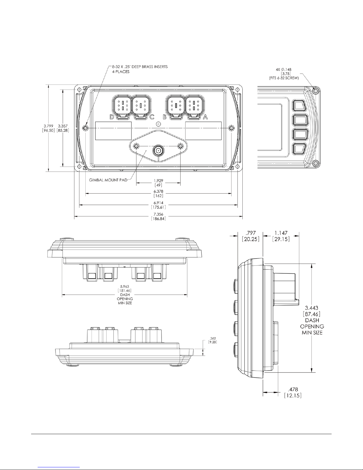
Dash-Mounted Installation.................................................................................................1
Wiring Instructions ....................................................................................................................4
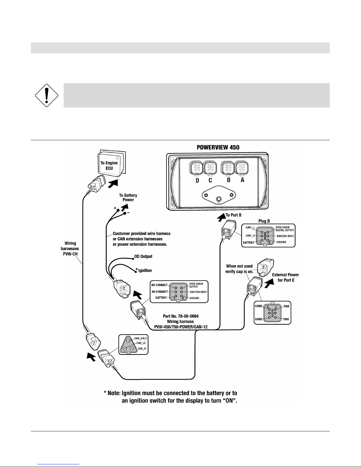
Single Engine.......................................................................................................................4
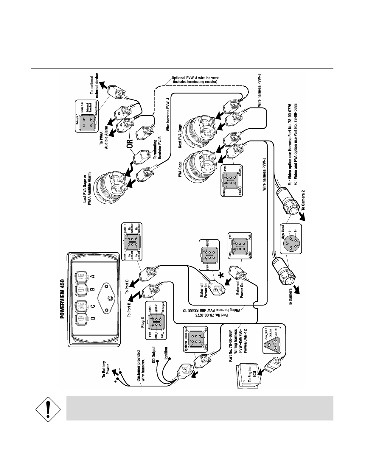
PVA Gages ...........................................................................................................................5
NMEA Gages........................................................................................................................6
Dual Engine Gages .............................................................................................................7
USB Wiring...........................................................................................................................8
Analog Video .......................................................................................................................9
No Video Wiring.................................................................................................................10
Pin Specifications for Deutsch DT04-6P Style Connections ......................................11
PV450 Features and Operations ............................................................................................12
Setting Up your PV450 Display for the First Time...............................................................13
Product Features......................................................................................................................15
Power Up ............................................................................................................................15
Main Menu ..........................................................................................................................15
Gauge Display ...................................................................................................................16
Engine Diagnostics...........................................................................................................18
Fault Code Popups ...........................................................................................................19
User Settings .....................................................................................................................20
Utilities ................................................................................................................................24
Specifications ...........................................................................................................................26
Addendum.................................................................................................................................27
How to Install a Configuration from a USB Drive for the PV450 ................................27

(THIS PAGE INTENTIONALLY LEFT BLANK)

Section 78 00-02-0732
2016-02-26 - 1 -
Hardware Installation
The following instructions will guide you through installing the PV450 display.
Inspecting Package Contents
Before attempting to install the product, it is recommended that you ensure all parts are
accounted for and inspect each item for damage (which sometimes occurs during shipping).
The items included in the box are:
Installation kit – P/N 78-00-0782 includes:
•4 ea. machine screws and flat washers
•4 Nylock nuts
•1 small bag
Dash-Mounted Installation
Tools needed.
•Drill with 5/32” size bit
•Jig Saw or tool that cleanly cuts through dash material.
•Wrench or socket
Preparing the Dash
Determine the location of the PowerView 450 in the dash. Use the Installation Template
(included at the end of the manual) as a guideline to cut a hole in the dash to the specified
dimensions. Drill holes where indicated on the template for the mounting screws.
NOTE: When using the paper template from the manual, please be aware that if
you downloaded this document from the FW Murphy website, the pdf file may not
automatically print to scale. When submitting the file for print, you will need to
select “None” for Page Scaling. Check the accuracy of the printed template by
verifying the measurements labeled on the template are correct.
If this manual was supplied with your product, the template will be correct.

Section 78 00-02-0732
2016-02-26 - 2 -
Front Installation of Display
1. Place the back side of the display through the opening in the dash.
2. Use the 4 screws to line up the unit with the drilled holes.
3. Push the unit through the opening and screws through the drilled holes until the back of
the case is flush.
4. Use the Nylock nuts provided to tighten unit to the dash. Use the appropriate wrench or
socket to tighten. Torque lock nuts to 8-10 inch pounds.
Back Installation of Display
1. Cut the dash to allow for the display. Ensure the materials are available to properly
secure the unit within the dash. Torque the 6-32 Nylock nuts to 5 inch pounds.
2. Place the display behind dash and line up the four mounting holes on the display with
the holes in dash.
3. Install four bolts and tighten nuts.
Gimbal Mounted Installation
If it is desired to gimbal-mount the PV450, the gimbals can be sourced from Ram Mounting
Systems, Inc. at www.ram-mount.com
The RAM parts, drawings and models are accompanied by a ordering guide at
http://www.rammount.com/SupportCenter/GlossaryofTerms/tabid/149/Default.aspx
The PV450 has a matching bolt pattern for the RAM Diamond base with 9/16” ball
(P/N RAM-A-238).

Section 78 00-02-0732
2016-02-26 - 3 -
Dimensions for Installation

Section 78 00-02-0732
2016-02-26 - 4 -
Wiring Instructions
The following illustrations are examples of various typical quick-connect options for setup.
Wiring harnesses are sold separately.
WARNING: Failure to install the unit per the specified wiring diagrams may cause
damage to the unit. DO NOT connect power to the video ground. Warranty is void
for damage caused by incorrect wiring.
Single Engine

Section 78 00-02-0732
2016-02-26 - 5 -
PVA Gages
WARNING: Failure to install the unit per the specified wiring diagrams may cause
damage to the unit. DO NOT connect power to the video ground. Warranty is void
for damage caused by incorrect wiring.

Section 78 00-02-0732
2016-02-26 - 6 -
NMEA Gages

Section 78 00-02-0732
2016-02-26 - 7 -
Dual Engine Gages
NOTE: Port B and C connectors are keyed differently than Port A and D
connectors to ensure proper connection.

Section 78 00-02-0732
2016-02-26 - 8 -
USB Wiring

Section 78 00-02-0732
2016-02-26 - 9 -
Analog Video
WARNING: Failure to install the unit per the specified wiring diagrams may cause
damage to the unit. DO NOT connect power to the video ground. Warranty is void
for damage caused by incorrect wiring.

Section 78 00-02-0732
2016-02-26 - 10 -
No Video Wiring
WARNING: Failure to install the unit per the specified wiring diagrams may cause
damage to the unit. DO NOT connect power to the video ground. Warranty is void
for damage caused by incorrect wiring.

Section 78 00-02-0732
2016-02-26 - 11 -
Pin Specifications for Deutsch DT04-6P Style Connections
WARNING: Failure to install the unit per the specified wiring diagrams may cause damage
to the unit. DO NOT connect power to the video ground. Warranty is void for damage
caused by incorrect wiring.
Signal Definitions
•CAN: 2.0A and 2.0B
•1 port isolated according to NMEA 2000 (optional)
•USB 2.0, Video input (optional): NTSC/PAL, analog input (1) 0-5 VDC or 4-20 mA
•Digital output, capable of syncing 500mA.

Section 78 00-02-0732
2016-02-26 - 12 -
PV450 Features and Operations
LCD Screen Display
A color screen displays gauges, soft key commands, and fault messages, as well as menu
options for setup and configuration.
Soft Key Commands
Columns of vertical commands may be located to the left and/or right of the display. They will
change according to the options available for the screen being displayed.
Soft Keys
The soft keys correspond to the soft key commands and allow selections to be made
accordingly.
MENU Key
The bottom left key is a soft key reserved in most cases for the Menu. In rare cases, it could be
used for other options. Pressing the MENU key at any time displays the list of menu options. If
not labeled, it is the MENU key.
ENTER Key
The bottom right key is a soft key reserved in most cases for the Enter. In rare cases, it could
be used for other options. Pressing the ENTER key will select the option displayed much like
the ENTER key on a keyboard. If not labeled, it is the ENTER key

Section 78 00-02-0732
2016-02-26 - 13 -
Setting Up your PV450 Display for the First Time
The guidelines presented below are intended for setting up the PV450 display for the first time.
Once the configuration is set up, there is no need to revisit or change any of the settings.
NOTE: If you require assistance during the set up process, contact FW Murphy
customer support at +1(918) 317-4100.
1. At the main menu, press the soft key to the left of ‘Utilities’.
2. The Utilities sub-menu is displayed.
3. From the ‘Utilities’ sub-menu, select ‘System Settings’. The following screen is
displayed.
4. With the cursor highlighting the J1939 source addresses, use the left side soft keys to
scroll through the ports and the right side soft keys to change the address. Press the

Section 78 00-02-0732
2016-02-26 - 14 -
Save key to save selected changes or the Restore Defaults key to return to the default
settings.

Section 78 00-02-0732
2016-02-26 - 15 -
Product Features
Power Up
There are two options to connecting the PV450 display:
•The battery and ignition inputs to display are both connect to the battery
•The battery input is connected to the battery and the ignition input is connected to the
ignition switch.
NOTE: If both are connected to the battery, then an inline battery
disconnect must be installed.
When the ignition is turned on, the PV450 display powers up and the engine health statistics
can be viewed via preset gauges. To see more gauge screens, press the Enter key.
Main Menu
The main menu is activated at any time by pressing the Menu key on the display.
The following features are accessed through the main menu:
•Gauge Display – provides a series of screens that display engine and auxiliary
information in a variety of formats.
•Engine Diagnostics – displays a list of engine fault codes and descriptions through a
DM1 message structure.
•User Settings – allows you to customize the display options for ambient light and
brightness, set US or metric units, language, specify the Home screen and screen setup
status.
•Utilities – allows configuration of the plug address. Also displays software version
information at the top of the page.

Section 78 00-02-0732
2016-02-26 - 16 -
Gauge Display
The Gauge Display screen consists of several predefined layouts that contain combinations of
analog gauges, straight bar gauges, or digital (text) readouts. These screens are displayed
upon startup.
To scroll through the various gauge screens, press the Prev and Next soft keys. This can be
repeated until all screens have been viewed. The currently displayed screen will stay active
until another key is pressed.
Soft Key Commands
When a Gauge Display screen is active, pressing the Enter key will display soft key
commands, as shown below. Continuing to press Enter will toggle through any additional soft
keys, and will eventually remove the soft key commands from the screen.
Soft Key commands provide quick navigation and access to the following features:
•Home
•Prev
•Day/Night
•Video (optional)
•Next
Home - This one-touch navigation feature allows a pre-defined Home screen to be accessed
from the available Gauge Display screens. Once selected, the Home screen will be displayed
anytime the Home key is pressed.
NOTE: For instructions on how to setup the Home screen, refer to the “User
Settings” section of this manual.
Table of contents
Other Murphy Automobile Electronic manuals
Popular Automobile Electronic manuals by other brands

Rear view safety
Rear view safety RVS-8129900Q instruction manual

iBeam
iBeam TE-CPSS product manual

Axxess
Axxess AXTC-FD3 installation instructions

Corvette
Corvette C6-HF Quick Start Bluetooth Installation Guide

Nokia
Nokia 6090 user guide

EverFocus
EverFocus Smart Heavy-Duty Vehicle TPMS Solution Quick installation guide

Renault
Renault Highway and Traffic Jam Companion Vehicle user manual

Dension
Dension AVR-9202-3 installation guide

Seat
Seat COMMUNICATION SYSTEM owner's manual

PAC
PAC RadioPRO 5 RP5-GM41 quick start guide

Seastar Solutions
Seastar Solutions Optimus 360 Operating instructions & user manual

Toyota
Toyota Frameless manual