ICP DAS USA I-2533T-FD User manual

I-2533T-FD ( CAN/CAN FD to Multi-mode Fiber Bridge ) User Manual (version 1.0.0) Page: 1
Copyright © 2021 ICP DAS Co., Ltd. All Rights Reserved. E-mail: service@icpdas.com
I-2533T-FD
User Manual
Version 1.0.0, April. 2021
Service and usage information for
I-2533T-FD

I-2533T-FD ( CAN/CAN FD to Multi-mode Fiber Bridge ) User Manual (version 1.0.0) Page: 2
Copyright © 2021 ICP DAS Co., Ltd. All Rights Reserved. E-mail: service@icpdas.com
Warranty
All products manufactured by ICP DAS are under warranty regarding defective
materials for a period of one year, beginning from the date of delivery to the
original purchaser.
Warning
ICP DAS assumes no liability for any damage resulting from the use of this
product.ICP DAS reserves the right to change this manual at any time without
notice. The information furnished by ICP DAS is believed to be accurate and
reliable. However, no responsibility is assumed by ICP DAS for its use, not for any
infringements of patents or other rights of third parties resulting from its use.
Copyright
Copyright @ 2021 by ICP DAS Co., Ltd. All rights are reserved.
Trademark
The names used for identification only may be registered trademarks of their
respective companies.
Contact us
If you have any problem, please feel free to contact us.
You can count on us for quick response.
Email: service@icpdas.com

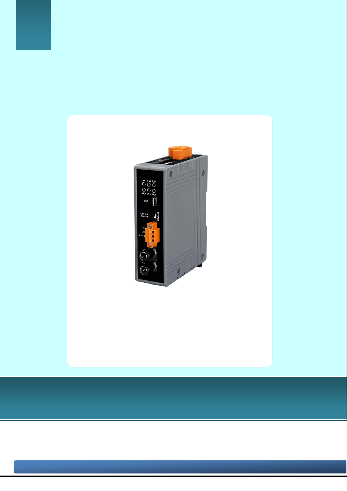
I-2533T-FD ( CAN/CAN FD to Multi-mode Fiber Bridge ) User Manual (version 1.0.0) Page: 3
Copyright © 2021 ICP DAS Co., Ltd. All Rights Reserved. E-mail: service@icpdas.com
Table of Contents
1. Introduction .......................................................................................................5
1.1. Specifications...............................................................................................7
1.2. Features........................................................................................................9
2. Technical data..................................................................................................10
2.1. Block Diagram ..........................................................................................10
2.2. Appearance................................................................................................11
2.3. Pin Assignment..........................................................................................12
2.4. 10-pin Dip Switch......................................................................................14
2.5. LED Indicator...........................................................................................16
2.6. Terminal Resistor Setup...........................................................................17
2.7. Module Group ID .....................................................................................19
2.8. Wire Connection.......................................................................................21
3. Network Deployment .......................................................................................22
3.1. Driving Capability....................................................................................22
3.2. Fiber Selection & Fiber Length...............................................................23
4. Software Utility ................................................................................................24
4.1. Install the I-2533CS-FD Utility...............................................................24
4.2. Setting up the I-2533T-FD .......................................................................27
4.3. Start to use I-2533CS-FD Utility tool .....................................................28
4.3.1. Connect to the module........................................................................29
4.3.2. Get Current Module Settings............................................................30
4.3.3. Configure User-Defined CAN Baudrate ..........................................31
4.3.4. Configure Other Parameters.............................................................32
4.3.5. Configure CAN ID Filter...................................................................34
5. Firmware Upgrade...........................................................................................36
6. Appendix...........................................................................................................40
6.1. Revision History........................................................................................40
6.2. Dimension..................................................................................................41
6.3. CAN Status Register.................................................................................42

I-2533T-FD ( CAN/CAN FD to Multi-mode Fiber Bridge ) User Manual (version 1.0.0) Page: 4
Copyright © 2021 ICP DAS Co., Ltd. All Rights Reserved. E-mail: service@icpdas.com
6.4. CAN Error Counter Register..................................................................43
6.5. Valid CAN FD Data Phase Bit Rat .........................................................44

I-2533T-FD ( CAN/CAN FD to Multi-mode Fiber Bridge ) User Manual (version 1.0.0) Page: 5
Copyright © 2021 ICP DAS Co., Ltd. All Rights Reserved. E-mail: service@icpdas.com
1. Introduction
The I-2533T-FD is a local CAN/CAN FD (CAN with Flexible Data-Rate) bridge used
to establish a connection between two CAN bus system via multi-mode fiber optic
transmission medium. In order to solve the problem between CAN/CAN FD and fiber
transmission medium, the I-2533T-FD is specially designed for converting the electrical
CAN/CAN FD bus signal to fiber optic cables. Besides, I-2533T-FD has three more
important features.
First, the transmission distance limitation of the CAN bus system will not affected
due to the different CAN/CAN FD baud rate. It means that the total CAN/CAN FD bus
working distance can be extended. Second, the bus error on one CAN/CAN FD network
will not affect the operation of another CAN/CAN FD network. Finally, the two CAN/CAN
FD network can communication with each other by using different CAN/CAN FD baud
rate for highly flexibility.
The I-2533T-FD is designed for multi-mode fiber, and allow to extern CAN/CAN FD
bus to maximum 2 km. Besides, I-2533T-FD provides the group function, which is the
basic message router. Users can decide the CAN/CAN FD message flows between
several CAN/CAN FD bus systems. I-2533T-FD also provides the utility tool for
user-defined baud rate and filter configuration. By using this tool, it is allowed to have
user-defined baud rate and CAN/CAN FD message filter. When users use the
I-2533T-FD on two CAN/CAN FD network with different CAN baud rate, it may be useful
to reduce the bus loading of the network which has low baud rate.

I-2533T-FD ( CAN/CAN FD to Multi-mode Fiber Bridge ) User Manual (version 1.0.0) Page: 6
Copyright © 2021 ICP DAS Co., Ltd. All Rights Reserved. E-mail: service@icpdas.com

I-2533T-FD ( CAN/CAN FD to Multi-mode Fiber Bridge ) User Manual (version 1.0.0) Page: 7
Copyright © 2021 ICP DAS Co., Ltd. All Rights Reserved. E-mail: service@icpdas.com
1.1. Specifications
Model Name
I-2533T-FD
CAN Interface
Transceiver TI TCAN1042HG
Channel Number 1
Connector 3-pin terminal-block connector
Transmission Speed CAN bit rates: 10 ~ 1000 kbps,
CAN FD bit rates for data field: 100 ~ 10000 kbps
Terminal Resistor DIP switch for the 120 Ω terminal resistor
Isolation 3000 VDC for DC-to-DC, 2500 Vrms for photocoupler
Specification ISO 11898-2, CAN 2.0 A/B and FD
CAN Filter
Configuration Selectable via Utility tool
Receive Buffer 128 data frames
Fiber Interface
Type ST type ; multi-mode ; 100 Base-FX
Wave Length (nm) 1310
Fiber Cable (μm) 50/125, 62.5/125 or 100/140 (62.5/125 μm recommended)
Transmission Distance
(km) 2 (theoretical value)
Min. TX Output (dBm) -20
Max. TX Output (dBm) -14
Max. RX Sensitivity
(dBm) -32
Max. RX Overload
(dBm) -8
Budget (dBm) 12
USB Interface
Connector 1 x USB (Mini-B)
Compatibility USB 2.0 High Speed (480Mbps)
Software Driver Built-in Windows 7/8.1/10
LED

I-2533T-FD ( CAN/CAN FD to Multi-mode Fiber Bridge ) User Manual (version 1.0.0) Page: 8
Copyright © 2021 ICP DAS Co., Ltd. All Rights Reserved. E-mail: service@icpdas.com
Round LED PWR, FB_Ack, FB_Err, CAN_Err, CAN_Tx and CAN_Rx LEDs
Power
Power supply Unregulated +10 ~ +30 VDC
Protection Power reverse polarity protection, Over-voltage brown-out protection
Power Consumption 0.125A @ 24VDC
Mechanism
Installation DIN-Rail
Dimensions 33.0 mm x 127 mm x 101 mm (W x L x H)
Environment
Operating Temp. -25 ~ 75 ℃
Storage Temp. -30 ~ 80 ℃
Humidity 10 ~ 90% RH, non-condensing

I-2533T-FD ( CAN/CAN FD to Multi-mode Fiber Bridge ) User Manual (version 1.0.0) Page: 9
Copyright © 2021 ICP DAS Co., Ltd. All Rights Reserved. E-mail: service@icpdas.com
1.2. Features
Compatible with the ISO 11898-2 standard
Compatible with CAN specification 2.0 A/B and FD
CAN FD support for ISO and Non-ISO (Bosch) standards switchable
CAN FD bit rates for data field from 100 kbps to 10000 kbps
CAN bit rates from 10 kbps to 1000 kbps
Fiber broken line detection
Support CAN Bus message filter configuration
Support firmware update via USB
Basic CAN message routing function via Group ID settings.
Built-in switchable 120 ohm terminal resistor for CAN Bus
Dip switch for CAN/CAN FD baud rate configuration

I-2533T-FD ( CAN/CAN FD to Multi-mode Fiber Bridge ) User Manual (version 1.0.0) Page: 10
Copyright © 2021 ICP DAS Co., Ltd. All Rights Reserved. E-mail: service@icpdas.com
2. Technical data
2.1. Block Diagram
The following figure is the block diagram illustrating the functions of the I-2533T-FD.
Figure 2-1-1 Block Diagram of I-2533T-FD

I-2533T-FD ( CAN/CAN FD to Multi-mode Fiber Bridge ) User Manual (version 1.0.0) Page: 11
Copyright © 2021 ICP DAS Co., Ltd. All Rights Reserved. E-mail: service@icpdas.com
2.2. Appearance
Figure 2-2-1 Appearance of I-2533T-FD

I-2533T-FD ( CAN/CAN FD to Multi-mode Fiber Bridge ) User Manual (version 1.0.0) Page: 12
Copyright © 2021 ICP DAS Co., Ltd. All Rights Reserved. E-mail: service@icpdas.com
2.3. Pin Assignment
The pin assignments of USB, CAN port, fiber port and power connector of
I-2533T-FD is shown in the following tables.
Table 2-3-1 Pin Assignment
Port Name Description
USB USB Used for configuration utility
CAN CAN_L CAN_Low, signal line of CAN port.
CAN_H CAN_High, signal line of CAN port.
CAN_GND
CAN_Ground, ground voltage level of CAN port.
Fiber TxD Transmit optic data.
RxD Receive optic data.
Power
+Vs Voltage Source Input. +10VDC ~ +30VDC.
GND Power Ground.
F.G. Frame Ground.

I-2533T-FD ( CAN/CAN FD to Multi-mode Fiber Bridge ) User Manual (version 1.0.0) Page: 13
Copyright © 2021 ICP DAS Co., Ltd. All Rights Reserved. E-mail: service@icpdas.com
Sometimes, the CAN_GND voltage level of different CAN devices on a CAN bus
system are not equal. In this case, it could cause some problems and derogate the
system stability. There is one way to relieve this situation; users can connect the
CAN_GND of different CAN devices with each other to balance the voltage level of
CAN_GND.
Electronic circuits are always influenced by different levels of Electro-Static
Discharge (ESD), which become worse in a continental climate area. F.G. provides a
path for conducting the ESD to the earth ground. Therefore, connecting the F.G
correctly can enhance the capability of the ESD protection and improve the module’s
reliability.
Wiring of CAN_GND and F.G. is not necessary; users can modify the configuration
of wiring according to real applications.

I-2533T-FD ( CAN/CAN FD to Multi-mode Fiber Bridge ) User Manual (version 1.0.0) Page: 14
Copyright © 2021 ICP DAS Co., Ltd. All Rights Reserved. E-mail: service@icpdas.com
2.4. 10-pin Dip Switch
When users would like to set the CAN/CAN FD baud rate, module’s group id or
update the firmware of the I-2533T-FD, Users can use the 10-pin dip switch on the
upper of the power connector to achieve these purposes. Users can find it on the top of
the power connector.
Figure 2-4-1 Location of 10-pin Dip Switch

I-2533T-FD ( CAN/CAN FD to Multi-mode Fiber Bridge ) User Manual (version 1.0.0) Page: 15
Copyright © 2021 ICP DAS Co., Ltd. All Rights Reserved. E-mail: service@icpdas.com
About the function of the 10-pin dip switch, they are described on the following
table. Table 2-4-1 Description of 10-pin Dip Switch
10-pin dip switch Pin Switch Function
Description
■
: ON
□
: OFF
1 ~ 3
Arbitration Bit
Rate of
CAN/CAN FD
message
Bit Rate (kbps)
1
2
3
10
□
□
□
20
■
□
□
50
□
■
□
125
■
■
□
250
□
□
■
500
■
□
■
800
□
■
■
1000
■
■
■
4 ~ 6
Data Phase Bit
Rate of CAN FD
message
Bit Rate (kbps) 4 5 6
100
□
□
□
125
■
□
□
250
□
■
□
500
■
■
□
800
□
□
■
1000
■
□
■
2000
□
■
■
3000
■
■
■
7 Bit Rate Mode
ON:
Use Arbitration/ Data Phase bit rate setting
by Utility configuration
OFF:
Use Arbitration/ Data Phase bit rate setting
by dip switch setting
8 ~ 9 Module’s group
ID
Group ID value 8 9
00
□
□
01
■
□
02
□
■
03
■
■
10 Firmware
upgrade mode
ON:
Into firmware upgrade mode.
OFF:
Into normal operating mode.

I-2533T-FD ( CAN/CAN FD to Multi-mode Fiber Bridge ) User Manual (version 1.0.0) Page: 16
Copyright © 2021 ICP DAS Co., Ltd. All Rights Reserved. E-mail: service@icpdas.com
2.5. LED Indicator
There are 6 LEDs on the I-2533T-FD. One for power indication, two for fiber
indication and three for CAN bus indication. The LED assignment and description are
shown as follows.
Figure 2-5-1 LED Assignment of I-2533T-FD
Table 2-5-1 LED Description
LED Name
Color
Description
PWR
Red
When power on the I-2533T-FD, this LED is turned on.
FB_Ack Green When the I-2533T-FD sends/receives one message to/from
the fiber, this LED flashes once.
FB_Err Orange If the I-2533T-FD detects the RXD line of the fiber is off, this
LED is always on.
CAN_Err Red
1. If the I-2533T-FD detects the bus-off status on the CAN
bus, this LED is always on.
2. If the CAN data buffer is full, this LED flashes once per
second.
3. If the I-2533T-FD can’t send CAN/CAN FD messages
successfully because the bus connector is off or some
errors happen, this LED flashes five times per second.
CAN_Tx Green
When the I-2533T-FD transmits one CAN/CAN FD message
to CAN bus, this LED flashes once.
CAN_Rx Green When the I-2533T-FD receives one CAN/CAN FD message
from CAN bus, this LED flashes once.
NOTE:
In “Firmware Upgrade Mode”, the CAN_Err, CAN_Tx, CAN_Rx and FB_Err LEDs will
flash per 500 milliseconds.

I-2533T-FD ( CAN/CAN FD to Multi-mode Fiber Bridge ) User Manual (version 1.0.0) Page: 17
Copyright © 2021 ICP DAS Co., Ltd. All Rights Reserved. E-mail: service@icpdas.com
2.6. Terminal Resistor Setup
In order to minimize the reflection effects on the CAN bus line, the CAN bus line has
to be terminated at both ends by two terminal resistors as in the following figure.
According to the ISO 11898-2 spec, each terminal resistor is 120Ω (or between
108Ω~132Ω). The bus topology and the positions of these terminal resistors are shown
as following figure.
Figure 2-6-1 CAN bus network topology
Each I-2533T-FD includes one build-in 120Ω terminal resistor, users can decider to
enabl it or not. The DIP switch for terminal resistor is on the upper of the CAN
connector.
Figure 2-6-2 Location of Terminal resistor DIP Switch

I-2533T-FD ( CAN/CAN FD to Multi-mode Fiber Bridge ) User Manual (version 1.0.0) Page: 18
Copyright © 2021 ICP DAS Co., Ltd. All Rights Reserved. E-mail: service@icpdas.com
The following DIP switch statuses present the condition if the terminal resistor is
active (default) or inactive.
Figure 2-6-3 Adjustment of Terminal Resistance
Generally, if your application is as follows, we recommend you to enable the
terminal resistor.
Figure 2-6-4 Application 1
If your application is like the structure as follows, the terminal resistor is not needed.
Figure 2-6-5 Application 2

I-2533T-FD ( CAN/CAN FD to Multi-mode Fiber Bridge ) User Manual (version 1.0.0) Page: 19
Copyright © 2021 ICP DAS Co., Ltd. All Rights Reserved. E-mail: service@icpdas.com
2.7. Module Group ID
The CAN port with the same “Group ID” setting can communicate with each other
via fiber optics. This setting is used for I-2533T-FD to communicate with the others
modules on star topology application.
Users can decide the value from 0 to 3 via pin 8 ~ 9 on 10-pin dip switch. The dip
switch for “Group ID” is over the power connector.
Figure 2-7-1 Location of Group ID DIP Switch

I-2533T-FD ( CAN/CAN FD to Multi-mode Fiber Bridge ) User Manual (version 1.0.0) Page: 20
Copyright © 2021 ICP DAS Co., Ltd. All Rights Reserved. E-mail: service@icpdas.com
The following DIP switch statuses present the “Module Group ID” value.
Table 2-7-1 Group ID Description
10-pin dip switch Pin Switch
Function Description
■
: ON
□
: OFF
8 ~ 9 Module’s
group ID
Group ID
value 8 9
00
□
□
01
■
□
02
□
■
03
■
■
The following “Module Group ID” values of device A and B present these ID are in the
same group which can communicate with each other.
Table 2-7-2 Group of “Module Group ID”
Items Device A Group ID value Device B Group ID value
1
00
00
2
01
01 or 03
3
02
02 or 03
4
03
01 or 02 or 03
For example, there are three CAN networks, NetworkA, Network B and Network C, and
each of them uses one I-2533T-FD. The Group IDs of the I-2533T-FDs are 1, 2, and 3
respectively. The Network A can exchange the data with Network C because the Group
IDs of the I-2533T-FDs are in the same group (the second rule in the above table). The
Network B can exchange the data with Network C, which follows the third rule in the
above table. The Network A can’t connect with the Network B because these two
I-2533T-FDs are not in the same group.
Other manuals for I-2533T-FD
1
Table of contents
Other ICP DAS USA Industrial Equipment manuals
Popular Industrial Equipment manuals by other brands

Pfeiffer Vacuum
Pfeiffer Vacuum PCR 280 operating instructions

Lincoln
Lincoln Impinger 1100 Series Installation, operation and maintenance manual

ABB
ABB Relion 670 series Commissioning manual

optris
optris Top-down GIS Operator's manual

Edge Technologies
Edge Technologies Patriot Series Operation manual

GESTRA
GESTRA BK 45 Original Installation Instructions