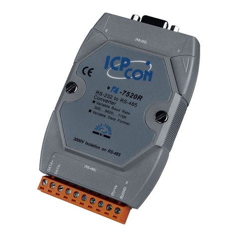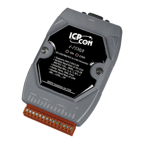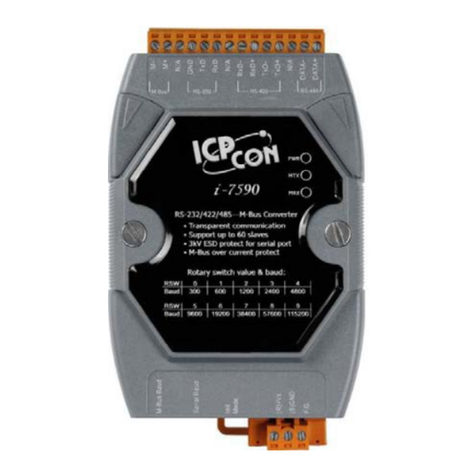
I-7530, I-7530A, I-7565, I-7530-FT, tM-7530, tM-7530A, tM-7565 User Manual Version 1.6 Page: 2
Copyright © 2018 ICP DAS Co., Ltd. All Rights Reserved E-mail: service@icpdas.com
Table of Contents
1. Introduction------------------------------------------------------------------------------------------5
1.1 Features and differences of CAN converter series --------------------------------------7
1.2 Communication Mode Description---------------------------------------------------------12
1.2.1 Normal mode------------------------------------------------------------------------------12
1.2.2 Pair Connection mode ------------------------------------------------------------------14
1.2.3 Listen only mode ------------------------------------------------------------------------- 15
2. Hardware information of CAN converter-------------------------------------------------- 17
2.1 Specification Table ---------------------------------------------------------------------------- 17
2.2 Pin Assignment -------------------------------------------------------------------------------- 19
2.3 Block Diagram---------------------------------------------------------------------------------- 22
2.4 Wiring method----------------------------------------------------------------------------------24
2.5 Terminal resistor-------------------------------------------------------------------------------28
2.6 Init / Normal DIP switch---------------------------------------------------------------------- 32
2.7 LED indicator----------------------------------------------------------------------------------- 34
3. Software for setting and testing (VxCAN Utility)--------------------------------------- 37
3.1 Search and setting interface---------------------------------------------------------------- 38
3.2 UART setting -----------------------------------------------------------------------------------40
3.3 CAN setting-------------------------------------------------------------------------------------43
3.4 Communcation mode setting ---------------------------------------------------------------46
3.5 Saving and default value -------------------------------------------------------------------- 50
3.6 Testing interface ------------------------------------------------------------------------------- 51
4. UART command string ------------------------------------------------------------------------- 53
4.1 Checksum algorithm -------------------------------------------------------------------------- 55
4.2 tIIILDD…[CHK]<CR> ------------------------------------------------------------------------- 56
4.3 TIIIL[CHK]<CR> ------------------------------------------------------------------------------- 57
4.4 eIIIIIIIILDD…[CHK]<CR> -------------------------------------------------------------------- 58
4.5 EIIIIIIIIL[CHK]<CR>--------------------------------------------------------------------------- 59
4.6 S[CHK]<CR> -----------------------------------------------------------------------------------60
4.7 C[CHK]<CR> ----------------------------------------------------------------------------------- 62
4.8 P0BBDSPAE[CHK]<CR> --------------------------------------------------------------------63
4.9 P1B [CHK]<CR> -------------------------------------------------------------------------------65
4.10 P2BBDSPAE[CHK]<CR> -------------------------------------------------------------------- 66
4.11 P3SBCCCCCCCCMMMMMMMM [CHK]<CR>------------------------------------------68
