ICP ROCKY-3702EV User manual

ROCKY–3702EV Ver.4.x
CeleronTM & Pentium III Processor
With VGA & Ethernet SBC
©Copyright 1999 by ICP Electronics Inc. All Rights Reserved. Manual first
edition Apr.01, 1999.
The information in this document is subject to change without prior notice
in order to improve reliability, design and function and does not represent
a commitment on the part of the manufacturer.
In no event will the manufacturer be liable for direct, indirect, special,
incidental, or consequential damages arising out of the use or inability to
use the product or documentation, even if advised of the possibility of
such damages.
This document contains proprietary information protected by copyright. All
rights are reserved. No part of this manual may be reproduced by any
mechanical, electronic, or other means in any form without prior written
permission of the manufacturer.
Trademarks
ROCKY-3702EV is a registered trademark of ICP Electronics Inc. IBM PC
is a registered trademark of International Business Machines Corporation.
Intel is a registered trademark of Intel Corporation. AMI is a registered
trademark of American Megatrends, Inc. Other product names mentioned
herein are used for identification purposes only and may be trademarks
and/or registered trademarks of their respective companies.


ROCKY-3702EV Socket 370 CeleronTM & Pentium III
with AGP VGA & 10/100Mbps Ethernet SBC 1
Contents
1. Introduction.......................................................................3
1.1 Specifications..............................................................................4
1.2 What You Have...........................................................................6
2. Installation.........................................................................7
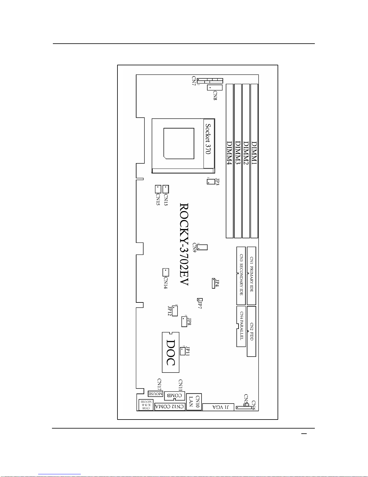
2.1 ROCKY-3702EV's Layout............................................................8
2.2 Unpacking Precautions................................................................9
2.3 Setting the CPU of ROCKY-3702EV ..........................................10
2.4 Watch-Dog Timer......................................................................10
2.5 DiskOnChip™ Flash Disk ..........................................................11
2.6 Clear CMOS Setup....................................................................11
2.7 PS/2 Mouse...............................................................................12
3. Connection......................................................................13
3.1 Floppy Disk Drive Connector......................................................13
3.2 PCI E-IDE Disk Drive Connector................................................14
3.3 Parallel Port...............................................................................15
3.4 Serial Ports................................................................................15
3.5 Keyboard/Mouse Connector.......................................................16
3.6 External Switches and Indicators ...............................................17
3.7 USB Port Connector ..................................................................17
3.8 IrDA Infrared Interface Port........................................................18
3.9 VGA Connector .........................................................................18
3.10 LAN RJ45 Connector.................................................................19
3.11 Fan Connector...........................................................................19

ROCKY-3702EV Socket 370 CeleronTM & Pentium III
with AGP VGA & 10/100Mbps Ethernet SBC 2
4. AMI BIOS Setup..............................................................20
4.1 Getting Start..............................................................................20
4.2 Standard CMOS Setup ..............................................................21
4.3 Advanced CMOS Setup.............................................................22
4.4 Advanced Chipset Setup............................................................24
4.5 Power Management Setup.........................................................26
4.6 PCI/PLUG AND PLAY Setup......................................................27
4.7 Peripheral Setup........................................................................28
4.8 Hardware Monitor Setup............................................................30
4.9 Change Supervisor/User Password............................................31
4.10 Auto-Detect Hard Disk...............................................................32
4.11 Auto Configuration with Optimal Settings...................................32
4.12 Auto Configuration with Fail Save Settings.................................33
4.13 Save Settings and Exit...............................................................33
4.14 Exit Without Saving...................................................................33
5. E2Key Function ...............................................................34
Appendix A. Watch-Dog Timer ...........................................36
Appendix B. ATX Power Supply.................................... 37-42

ROCKY-3702EV Socket 370 CeleronTM & Pentium III
with AGP VGA & 10/100Mbps Ethernet SBC 3
1
Introduction
Welcome to the ROCKY-3702EV Socket 370 Celeron®and
Pentium III ( FC-PGA ) with AGP VGA & 10/100Mbps Ethernet
Single Board Computer. The ROCKY-3702EV is a PICMG bus
form factor board. It is equipped with high performance Intel®
Celeron up to 500MHz and Pentium III ( FC-PGA ) 500MHz ( or
above ) Processor and advanced high performance multi-mode
I/O, designed for the system manufacturers, integrators, or
VARs that want to provide all the performance, reliability, and
quality at a reasonable price.
This board has a built-in DiskOnChip™(DOC) Flash Disk for
embedded application. The DOC Flash Disk is 100% compatible
to hard disk. User can use any DOS command without any extra
software utility. The DOC currently is available from 2MB to
144MB.
An advanced high performance super AT I/O chip –Winbond
W83977TF is used in the ROCKY-3702EV board. The on-chip
UARTs are compatible with the NS16C550. The parallel port and
IDE interface are compatible with IBM PC/AT architecture.
ROCKY-3702EV uses the advanced INTEL 440BX Chipset
which is 100% ISA/PCI compatible chipset with PCI 2.1
standard. In addition, this board provides four 168-pin sockets
for its on-board DRAM. The DIMM module is 3.3 V SDRAM and
max. 256MB for each module.

ROCKY-3702EV Socket 370 CeleronTM & Pentium III
with AGP VGA & 10/100Mbps Ethernet SBC 4
1.1 Specifications :
•CPU : support Intel Celeron®up to 500 MHz , Pentium III ( FC-PGA )
500 MHz ( or Above ) Processor.
•Bus : PICMG bus, meets PCI 2.1 standard
•DMA channels : 7
•Interrupt levels: 15
•Chipset : Intel 82440BX 66/100MHz CPU Clock
•RAM : Four 168-pin DIMM sockets support SDRAM and EDO RAM
module, up to 1GB.
•AGP VGA Controller : S3 Trio®3D/2x AGP VGA Controller
AGP bus speed : 133MHz
Screen Resolution up to
1600 x 1200 64K colors
1280 x 1024 64K colors
1024 x 768 16M colors
•10/100Mbps Ethernet Controller : Realtek RTL8139 IEEE802.u
100BASE-TX standard
Dual Auto-sensing interface to 10Mbps, 100Mbps Network
RJ45 connector for 10BASE-TX and 100BASE-TX
Full Duplex capability
Full Software driver support
•Ultra DMA/33 (Enhanced PCI IDE Interface) : up to four PCI
Enhance IDE hard drives. The Ultra DMA/33 IDE can handle data
transfer up to 33MB/s. The best of all is that this new technology is
compatible with existing ATA-2 IDE specifications. So, there is no
need to do any change for customer’s current accessory.
•Multi-I/O Chip : W83977, all I/O setup by BIOS
Two 16C550 RS-232C Ports
One EPP/ECP Parallel Port, Floppy Port
•Floppy disk drive interface : two 2.88 MB, 1.44MB, 1.2MB, 720KB,
or 360KB floppy disk drives.
•Two high speed Serial ports: NS16C550 compatible UARTs
•Bi-directional Parallel Port

ROCKY-3702EV Socket 370 CeleronTM & Pentium III
with AGP VGA & 10/100Mbps Ethernet SBC 5
•
Built-in LM78 Hardware Monitoring System to monitor power
supply voltage and fan speed status.
•IrDA port : Support Serial Infrared(SIR) and Amplitude Shift
Keyed IR(ASKIR) interface.
•USB port : Support two USB ports for future expansion.
•ISAPLUSTM : designed to enhance the ISA bus drive capability
•E2Key : A special designed 1Kbit EEPROM (non volatile memory)
provided to accept read/ write data by customer’s program. It is
useful to store system ID, Password, Critical Data on the board.
•Watch-dog timer : can be set by 1, 2, 10, 20, 110 or 220 seconds
period. Reset or NMI is generated when CPU does not periodically
trigger the timer. Your program uses hex 043 and 443 to control the
watch-dog and generate a system reset.
•Flash Disk -DiskOnChip™: The Flash Disk provides 100%
compatibility with hard disk, supports M-Systems. The built-in True
FFS Transparent Flash Block Management and Space Reclamation
will let customer to use the Flash Disk with DOS command, no need
any extra software utility. The DOC currently is available from 2MB
to 144MB.
•ATX Power Supply function
•Mouse & Keyboard Connector : PS/2 Mouse Port on-board + Ext.
Keyboard.
•Power Consumption : +5V/6.8A (Celeron 333MHz, 512MB SDRAM)
+12V:170mA , -12V:60mA
•Operating Humidity : 5 ~ 95 %, non-condensing

ROCKY-3702EV Socket 370 CeleronTM & Pentium III
with AGP VGA & 10/100Mbps Ethernet SBC 6
1.2 What You Have
In addition to this User's Manual, the ROCKY-3702EV package
includes the following items:
•ROCKY-3702EV Socket 370 Celeron®& Pentium III with AGP
VGA & 10/100Mbps Ethernet SBC
•Printer Cable/RS232 Cable
•FDD/HDD Cable
•6-pin Mini-Din to 5-pin Din Keyboard Adapter Cable
If any of these items is missing or damaged, contact the dealer
from whom you purchased the product. Save the shipping
materials and carton in case you want to ship or store the product
in the future.

ROCKY-3702EV Socket 370 CeleronTM & Pentium III
with AGP VGA & 10/100Mbps Ethernet SBC 7
2
Installation
This chapter describes how to install the ROCKY-3702EV. The
layout of ROCKY-3702EV is shown on the next page and the
Unpacking Precautions that you should be careful with are
described on the following page. Also included is the jumpers
and switches setting for this board’s configuration, such as: CPU
type selection, system clock setting and Watchdog timer.
2.1 ROCKY-3702EV 's Layout
< please, refer to the next page >

ROCKY-3702EV Socket 370 CeleronTM & Pentium III
with AGP VGA & 10/100Mbps Ethernet SBC 8
2.1 ROCKY-3702EV 's Layout

ROCKY-3702EV Socket 370 CeleronTM & Pentium III
with AGP VGA & 10/100Mbps Ethernet SBC 9
2.2Unpacking Precautions
Some components on ROCKY-3702EV SBC are very sensitive to
static electric charges and can be damaged by a sudden rush of
power. To protect it from unintended damage, be sure to follow
these precautions:
üGround yourself to remove any static charge before touching your
ROCKY-3702EV SBC. You can do it by using a grounded wrist
strap at all times or by frequently touching any conducting materials
that is connected to the ground.
üHandle your ROCKY-3702EV SBC by its edges. Don’t touch IC
chips, leads or circuitry if not necessary.
üDo not plug any connector or jumper while the power is on.
üDo not put your ROCKY-3702EV SBC unprotected on a flat surface
because it has components on both sides.

ROCKY-3702EV Socket 370 CeleronTM & Pentium III
with AGP VGA & 10/100Mbps Ethernet SBC 10
FREQUENCY
2.3Setting the CPU of ROCKY-3702EV
•
JP3 : CPU FREQUENCY SETTING
JP3
1-32-4
66MHz/100MHz ON ON
Note: Intel Celeron CPU will auto-detect 66MHz
Intel Pentium III ( FC-PGA ) CPU will auto-detect 100MHz
•JP8 : CPU MULTIPLIER SETTING
Ratio 1-23-45-67-8
3.0 x ON OFF ON ON
3.5 x ON OFF OFF ON
4.0 x OFF ON ON ON
4.5 x OFF ON OFF ON
5.0 x OFF OFF ON ON
5.5x OFF OFF OFF ON
6.0x ON ON ON OFF
6.5x ON ON OFF OFF
7x ON OFF ON OFF
7.5x ON OFF OFF OFF
8x OFF ON ON OFF
2.4Watch-Dog Timer
The Watch-Dog Timer is enabled by reading port 443H. It should
be triggered before the time-out period ends, otherwise it will
assume the program operation is abnormal and will issue a reset
signal to reboot or activate NMI to CPU. The Watch-Dog Timer
is disable by reading port 043H.
•JP5 : Watch-Dog Timer Type Setting
PIN NO. DESCRIPTION
1-2NMI
2-3RESET

ROCKY-3702EV Socket 370 CeleronTM & Pentium III
with AGP VGA & 10/100Mbps Ethernet SBC 11
•JP12 : WDT Time-out Period
PERIOD
1-23-45-67-8
1 sec. OFF OFF ON OFF
2 sec. OFF OFF ON ON
10 sec.
OFF ON OFF OFF
20 sec.
OFF ON OFF ON
110 sec.
ON OFF OFF OFF
220 sec.
ON OFF OFF ON
2.5 DiskOnChip™ Flash Disk
The DiskOnChip™ (DOC) Flash Disk Chip is produced by M-
Systems. Customers don‘t need any extra software utility
because the DOC is 100% compatible to hard disk. It is just
“plug and play”, easy and reliable. Right now, the DOC is
available from 2MB to 144MB.
•JP11 : DiskOnChip™ Memory Address Setting
PIN NO. ADDRESS
1-2CE00 –CFFF
3-4D600 –D7FF
5-6DE00 –DFFF
2.6 Clear CMOS Setup
If you forget the CMOS password, you can clear or reset it by
closing the JP4. After JP4 is closed, turn on the power for
about 3 seconds then turn it off and open the JP4. Now, the
password has been cleared from your CMOS.
•JP4 : Clear CMOS Setup
PIN NO. DESCRIPTION
2-3Normal Operation
3-4Clear CMOS Setup
Note: 1-4 is for connection with external battery (4=GND)

ROCKY-3702EV Socket 370 CeleronTM & Pentium III
with AGP VGA & 10/100Mbps Ethernet SBC 12
2.7PS/2 Mouse
•JP7 : PS/2 Mouse Setting
The PS/2 mouse uses IRQ12 while in operation.
JP7 DESCRIPTION
ON Enable the PS/2 Mouse, IRQ12
OFF Disable the PS/2 Mouse

ROCKY-3702EV Socket 370 CeleronTM & Pentium III
with AGP VGA & 10/100Mbps Ethernet SBC 13
3
Connection
This chapter describes how to connect peripherals, switches and
indicators to the ROCKY-3702EV board.
3.1 Floppy Disk Drive Connector
ROCKY-3702EV board equipped with a 34-pin daisy-chain driver
connector cable.
•CN2 : FDD CONNECTOR
PIN NO. DESCRIPTION
PIN NO. DESCRIPTION
1GROUND 2REDUCE WRITE
3GROUND 4N/C
5GROUND 6N/C
7GROUND 8INDEX#
9GROUND 10 MOTOR ENABLE A#
11 GROUND 12 DRIVE SELECT B#
13 GROUND 14 DRIVE SELECT A#
15 GROUND 16 MOTOR ENABLE B#
17 GROUND 18 D4IRECTION#
19 GROUND 20 STEP#
21 GROUND 22 WRITE DATA#
23 GROUND 24 WRITE GATE#
25 GROUND 26 TRACK 0#
27 GROUND 28 WRITE PROTECT#
29 GROUND 30 READ DATA#
31 GROUND 32 SIDE 1 SELECT#
33 GROUND 34 DISK CHANGE#

ROCKY-3702EV Socket 370 CeleronTM & Pentium III
with AGP VGA & 10/100Mbps Ethernet SBC 14
3.2 PCI E-IDE Disk Drive Connector
You can attach four IDE (Integrated Device Electronics) hard
disk drives to the ROCKY-3702EV IDE controller.
CN1 (IDE 1) : Primary IDE Connector
CN3 (IDE 2) : Secondary IDE Connector
•CN1/CN3 : IDE Interface Connector
PIN NO.
DESCRIPTION PIN NO.
DESCRIPTION
1RESET# 2GND
3DATA 7 4DATA 8
5DATA 6 6DATA 9
7DATA 5 8DATA 10
9DATA 4 10 DATA 11
11 DATA 3 12 DATA 12
13 DATA 2 14 DATA 13
15 DATA 1 16 DATA 14
17 DATA 0 18 DATA 15
19 GND 20 N/C
21 IDE DRQ 22 GND
23 IOW# 24 GND
25 IOR# 26 GND
27 IDE CHRDY 28 GND
29 IDE DACK 30 GND
31 INTERRUPT 32 N/C
33 SA 1 34 N/C
35 SA 0 36 SA 2
37 HDC CS0# 38 HDC CS1#
39 HDD ACTIVE# 40 GND

ROCKY-3702EV Socket 370 CeleronTM & Pentium III
with AGP VGA & 10/100Mbps Ethernet SBC 15
3.3 Parallel Port
This port is usually connected to a printer, The ROCKY-3702EV
includes an on-board parallel port, accessed through a 26-pin flat-
cable connector CN4.
•CN4 : Parallel Port Connector
PIN NO. DESCRIPTIONPIN NO. DESCRIPTION
1STROBE# 2DATA 0
3DATA 1 4DATA 2
5DATA 3 6DATA 4
7DATA 5 8DATA 6
9DATA 7 10 ACKNOWLEDGE
11 BUSY 12 PAPER EMPTY
13 PRINTER SELECT 14 AUTO FORM FEED #
15 ERROR# 16 INITIALIZE
17 PRINTER SELECT LN# 18 GND
19 GND 20 GND
21 GND 22 GND
23 GND 24 GND
25 GND 26 N/C
3.4 Serial Ports
The ROCKY-3702EV offers two high speed NS16C550
compatible UARTs with Read/Receive 16 byte FIFO serial ports
(COMA/COMB).
•CN12 : Serial Port 9-pin D-sub Connector (COMA)
PIN NO. DESCRIPTION
1DATA CARRIER DETECT (DCD)
2RECEIVE DATA (RXD)
3TRANSMIT DATA (TXD)
4DATA TERMINAL READY (DTR)
5GROUND (GND)
6DATA SET READY (DSR)
7REQUEST TO SEND (RTS)
8CLEAR TO SEND (CTS)
9RING INDICATOR (RI)

ROCKY-3702EV Socket 370 CeleronTM & Pentium III
with AGP VGA & 10/100Mbps Ethernet SBC 16
•CN11 : Serial Port 2x5 pin header Connector (COMB)
Pin No.
Description
Pin No.
Description
1 DCD 2 DSR
3 RXD 4 RTS
5 TXD 6 CTX
7 DTR 8 RI
9 GND 10 NC
3.5 Keyboard/Mouse Connector
The ROCKY-3702EV provides one external keyboard ,one
external mouse and one PS/2 keyboard & mouse connectors.
•CN8 : 5-pin Header External Keyboard Connector
PIN NO. DESCRIPTION
1KB CLOCK
2KB DATA
3N/C
4GND
5+5V
•CN18 : 6-pin Mini-DIN PS/2 Keyboard & Mouse Connector
PIN NO. DESCRIPTION
1KB DATA
2N/C
3GND
4+5V
5KB CLOCK
6N/C
•CN17 : PS/2 Mouse 5-pin Header Connector
PIN NO. DESCRIPTION
1MS DATA
2N/C
3GND
4+5V
5MS CLOCK

ROCKY-3702EV Socket 370 CeleronTM & Pentium III
with AGP VGA & 10/100Mbps Ethernet SBC 17
3.6 External Switches and Indicators
There are several external switches and indicators for
monitoring and controlling your CPU board. All the functions are
in the CN7 connector.
•CN7 : Multi Panel
PIN NO.
DESCRIPTION PIN NO.
DESCRIPTION
1. SPEAKER 2VCC
3. N/C 4N/C
5. N/C 6GND
7. +5V 8KEYLOCK
9. RESET SW 10 GND
11. GND 12 GND
13. IDE LED 14 N/C
15. +5V 16 ATX POWER CONTROL
17. ATX POWER BUTTON
18 ATX 5VSB
19. ATX 5VSB 20 ATX 5VSB
3.7 USB Port Connector
The ROCKY-3702EV has two built-in USB ports for the future
new I/O bus expansion.
•CN9: 2 USB Connectors
Pin 1,3,5,7 for USB 0
Pin 2,4,6,8 for USB 1
PIN NO. Description
PIN NO.
Description
1VCC 2GND
3SBD0-4SBD1+
5SBD0+ 6SBD1-
7GND 8VCC

ROCKY-3702EV Socket 370 CeleronTM & Pentium III
with AGP VGA & 10/100Mbps Ethernet SBC 18
3.8 IrDA Infrared Interface Port
ROCKY-3702EV built-in IrDA port supports Serial Infrared (SIR)
or Amplitude Shift Keyed IR (ASKIR) interface. If you want to
use the IrDA port, you have to configure the SIR or ASKIR
model in the BIOS’s Peripheral Setup’s COM2. Then the normal
RS-232 COM2 will be disabled.
•CN6 : IrDA Connector
PIN NO.
DESCRIPTION
1VCC
2FIR-RX
3IR-RX
4GND
5IR-TX
6CIR-RX
3.9 VGA Connector
The built-in 15-pin VGA connector can be connected directly to
your monochrome CRT monitor as well as high resolution color
CRT monitor.
•J1 : 15-pin Female Connector
1RED 9VCC
2GREEN 10 GND
3BLUE 11 N/C
4N/C 12 DDC DATA
5GND 13 H-SYNC
6GND 14 V-SYNC
7GND 15 DDC CLK
8GND
Table of contents
Other ICP Motherboard manuals
Popular Motherboard manuals by other brands

Baxi
Baxi Single Channel Digital Programmer Instruction manual for Installers and Users

Advantech
Advantech PCM-9370F Startup manual

Eurotech
Eurotech Bitsy G5 user manual

Industrial Computers
Industrial Computers ADE-6040 user manual

IWILL
IWILL mP4G2 Series user manual

EVGA
EVGA X299 Micro ATX 2 Installation