3
1
Introduction
Welcome to the ROCKY-3703EVR Celeron & Pentium® III
Single Board Computer. The ROCKY-3703EVR board is an
ISA/PCI form factor board, which comes equipped with high
performance Pentium® III Processor and advanced high
performance multi-mode I/O, designed for the system
manufacturers, integrators, or VARs that want to provide all the
performance, reliability, and quality at a reasonable price.
In addition, the ROCKY-3703EVR provides S3 Savage4 AGP4X
VGA on board. The VGA chip is 3D graphics chipset, which
provides up to 1920x1440x16-color resolution. The VGA on
board 2 to 32MB frame buffer using system memory.
This board has a built-in DiskOnChip™(DOC) Flash Disk Socket
for embedded applications. The DOC Flash Disk is 100%
software compatible with hard disks. Users can use any DOS
command without any extra software utility. The DOC currently
is available from 2MB to 144MB.
An advanced high performance super AT I/O chip – VIA
VT82C686B is used in the ROCKY-3703EVR board. Both on-
chip UARTs are compatible with the NS16C550. The parallel
port and IDE interface are compatible with IBM PC/AT
architecture.
The ROCKY-3703EVR uses dual Intel 82559 Fast Ethernet
Multifunction PCI Controller as a LAN controller. Which is a fully
integrated 10BASE-T/100BASE-TX LAN solution with high
performance networking functions and low power features.
The ROCKY-3703EVR uses the advanced VIA PM133/PL133
Chipset which is 100% ISA/PCI software compatible chipset with
PCI 2.1 standard.
4
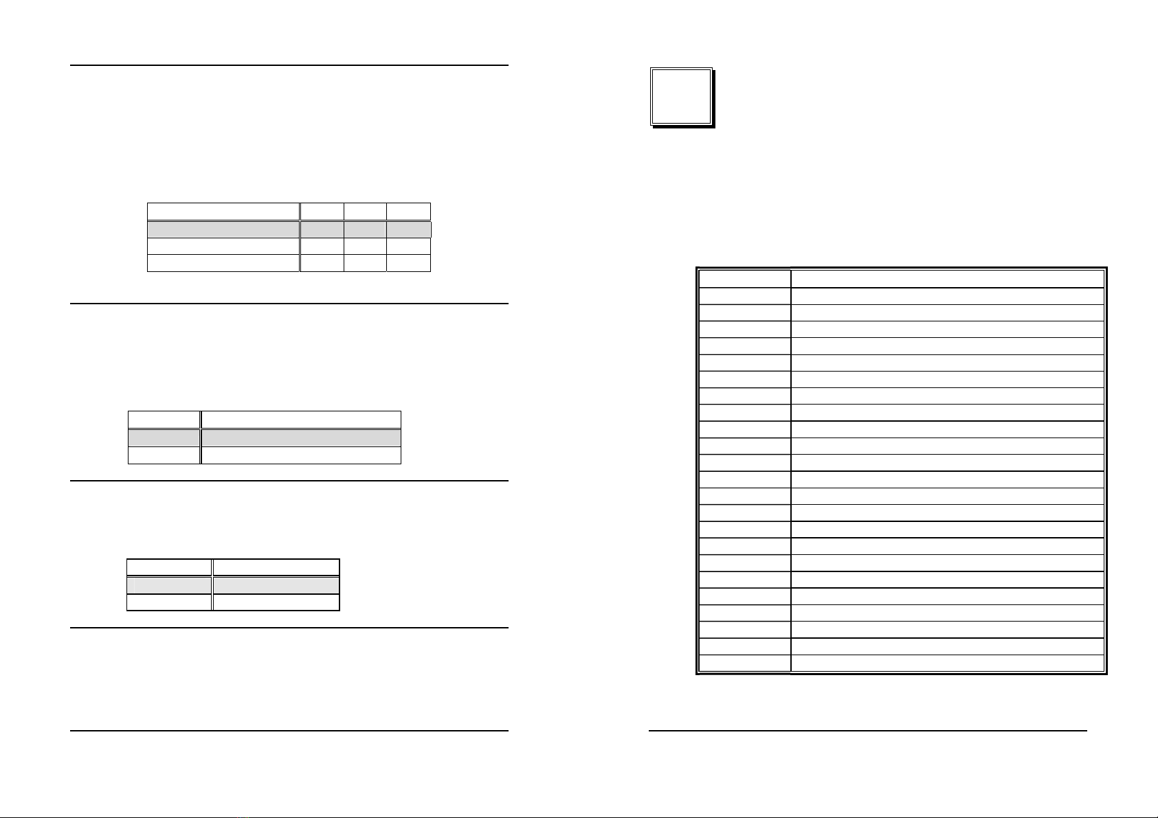
1.1 Specifications
CPU(PGA370) Intel Celeron® and Pentium® III (FC-PGA)
Processor, supports 66/100/133 MHz FSB
Bus interface PCI/ISA bus, PICMG compliant
Bus speed ISA : 8MHz, PCI: 33MHz
DMA channels 7
Interrupt levels
15
Chipset VIA PM133/PL133
Real-time
clock/calendar
VT82C686B
RAM memory
Three 168-pin DIMM sockets support SDRAM
and VCM RAM module. The max. Memory is up
to 1.5GB.
ATA/100
IDE interface
Up to four PCI Enhanced IDE hard drives. The
ATA/100 IDE can handle data transfer up to
100MB/s. Compatible with existing ATA-2 IDE
specifications its best advantage, so there is no
need to do any changes for users’ current
accessories.
Floppy disk
drive interface
Supports up to two floppy disk drives,
5.25”(360KB and 1.2MB) and/or 3.5” (720KB,
1.44MB, and 2.88MB)
Serial ports
Two RS-232 ports with 16C550 UART (or
compatible) with 16-byte FIFO buffer. Support up
to 115.2Kbps. Ports can be individually
configured to COM1, COM2 or disabled.
Bi-directional
parallel port
Configurable to LPT1, LPT2, LPT3 or disabled.
Supports EPP/ECP/SPP
Hardware
monitor
Built-in to monitor power supply voltage and fan
speed status