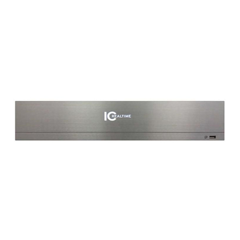
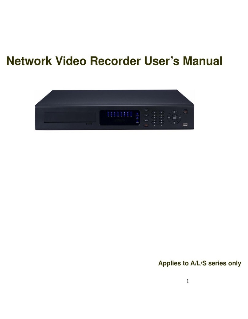
ICRealtime 1U POE NVR Series User manual

User's Manual
V4.1.1

Foreword
General
This manual introduces the functions and operations of the NVR device (hereinafter referred to
as "the Device"). Note that not all functions covered in this manual are available
depending on the actual model used.
Safety Instructions
The following categorized signal words with defined meanings might appear in the manual.
Signal Words
Meaning
Indicates a high potential hazard that, if not avoided, will result
in death or serious injury.
Indicates a medium or low potential hazard which, if not
avoided, could result in slight or moderate injury.
This indicates a potential risk that, if not avoided, could
result in property damage, data loss, lower performance, or
unpredictable result.
Provides methods to help you solve a problem or save you
time.
Provides additional information as the emphasis and
supplement to the text.
About the Manual
● The manual is for reference only. If there is any inconsistency between the manual and
the actual product, the actual product shall prevail.
● We are not liable for any loss caused by the operations that do not comply with the manual.
● The manual would be updated according to the latest laws and regulations of related regions.
For detailed information, see the manual, QR code, or our official website.
● All the designs and software are subject to change without prior written notice. The product
updates might cause some differences between the actual product and the manual. Please
contact technical support for the latest program and supplementary documentation.
● There still may be a deviation in technical data, functions and operations description, or
errors in print. If there is any doubt or dispute, please refer to our final explanation.
● All trademarks, registered trademarks, and the company names in the manual are the
properties of their respective owners.
● Please visit our website, contact the supplier or customer service if there is any problem
occurring when using the device

Important Safeguards and Warnings
The following statements describe the correct application methods for the device. Read the
manual carefully before use to prevent danger and property loss. Strictly conform to the
manual during application and keep it properly stored after reading for future reference.
Operating Requirements
● Install the PoE front-end device indoors.
● These devices do not support wall mounts.
● Do not place and install the device in an area exposed to direct sunlight or near a
heat-generating device.
● Do not install the device in a humid, dusty, or dirty area.
● Make sure the recorder is installed horizontally, at a stable location, and prevent it from
falling.
● Do not drip or splash liquids onto the device; do not put on the device anything filled
with liquids, in order to prevent liquids from flowing into the device.
● Install the device at well-ventilated places; do not block its ventilation opening(s).
● Power the device only within the rated input and output range.
● Do not dismantle the device arbitrarily.
● Transport, use, and store the device within the allowed humidity and temperature
range.
Power Requirements
● Make sure to use the designated power type. Otherwise, there may be a risk of fire or
explosion.
● Make sure to use power according to requirements. Otherwise, it may result in fire,
explosion, or burning risks of batteries!
● To replace batteries, only the same type of batteries can be used.
● Make sure to dispose of the exhausted batteries according to the instructions.
● The product shall use electric wires (power wires) recommended by this area, which
shall be used within its rated specification.
● Make sure to use a standard power adapter matched with this device. Otherwise, the
user shall undertake resulting personnel injuries or device damages.
● Use a power supply that meets SELV (safety extra-low voltage) requirements, and
supply power with a rated voltage that conforms to Limited Power Source in
IEC60950-1. For specific power supply requirements, please refer to device labels.
● Products with category I structure shall be connected to a grid power output socket,
which is equipped with protective grounding.
● The appliance coupler is a disconnecting device. During normal use, please keep an
angle that facilitates operation.

Table of Contents
Foreword 2
General 2
Safety Instructions 2
About the Manual 2
Important Safeguards and Warnings 4
Operating Requirements 4
Power Requirements 4
Table of Contents 5
1 Features 1
1.1 Overview 1
1.2 Features 1
2 Front and Rear Panel 3
2.1 Front Panel 3
2.1.1 1U POE NVR Series (NVR-MX08POE, NVR-MX16POE, NVR- FX08POE,
NVR-FX16POE) 3
2.2.2 2U NVR Series (NVR-7516K, NVR-EL32, NVR-EL64) 3
2.2 Rear Panel 5
2.2.1 1U POE NVR Series (NVR-MX08POE, NVR-MX16POE, NVR- FX08POE,
NVR-FX16POE) 5
2.2.2 2U POE NVR Series (NVR-7516K) 6
2.2.3 2U NVR Series (NVR-EL16, NVR-EL32, NVR-EL64) 8
2.3 Alarm Connection 10
2.3.1 Alarm Port 10
2.3.2 Alarm Input Port 11
2.3.3 Alarm Output Port 11
2.3.4 Alarm Relay Specification 12
2.4 Two-Way Talk 13
2.4.1 Device-end to Camera 13
2.4.2 PC-end to the Device-end 14
2.5 Mouse Operation 15
2.6 Remote Control 16
3 Device Installation 17
3.1 Inspecting NVR box contents 17
3.2 Product Label 18
3.3 HDD Installation 18
3.3.1 1U Series 18
3.3.2 1.5U Series 19
3.3.3 General 2U Series 21
3.4 Connection Examples 22

3.4.1 NVR-MX, NVR-FX and NVR-7516K Series 22
3.4.2 NVR-EL Series 23
4 Local Basic Operation 23
4.1 Getting Started 23
4.1.1 Booting up 24
4.1.2 Device Initialization 24
4.1.3 Resetting Password 28
4.1.3.1 Enabling Password Reset Function (If Available) 29
4.1.3.2 Resetting Password on Local Interface with Security Questions 29
4.1.3.3 Factory Reset Button (If Applicable) 31
4.1.4 Startup Wizard 31
4.1.4.1 General Settings 32
4.1.4.1.1 General 32
4.1.4.1.2 Date and Time 34
4.1.4.2 Basic Networking Settings 36
4.1.4.3 P2P 40
4.1.4.3.1 Local Operation 40
4.1.4.3.2 Mobile App Registration 41
4.1.4.4 Adding Camera 44
4.1.4.5 RAID Manager 48
4.1.4.6 Schedule
4.1.4.6.1 Recording Schedule 50
4.1.4.6.2 Snapshot Schedule 56
4.1.4.6.3 Record Control 58
4.2 Camera 59
4.2.1 Connection 59
4.2.1.1 Changing Camera IP address 60
4.2.1.2 Auto Changing Compression to H.265 61
4.2.1.3 IP Camera Export (Exporting Remote Devices) 61
4.2.1.4 IP Camera Import (Importing Remote Devices) 62
4.2.2 Remote Device Initialization 63
4.2.3 Shortcut Menu to Add Camera 66
4.2.4 Image 67
4.2.5 Video Overlay 70
4.2.5.1 Overlay 70
4.2.5.2 Privacy Masking 70
4.2.6 Encode 71
4.2.6.1 Encode 72
4.2.6.2 Snapshot 74
4.2.7 Channel Name 76
4.2.8 Checking PoE Status 77
4.2.9 Remote Update 77
4.2.10 Remote Device Info 78

4.3 Live View 78
4.3.1 Live View 79
4.3.2 Navigation bar 79
4.3.3 Live View Control Interface 80
4.3.3.1 Instant Replay 81
4.3.3.2 Digital Zoom 82
4.3.3.3 Instant Backup 83
4.3.3.4 Manual Snapshot 83
4.3.3.5 Two-way Talk 83
4.3.3.6 Switch Bit Streams 83
4.3.3.7 Shortcut Menu 83
4.3.3.8 Picture Search 85
4.3.4 Adding IC Home Devices 86
4.3.5 Sequence 87
4.3.6 Fisheye (Optional) 89
4.3.6.1 Fisheye de-warp during preview interface 89
4.3.6.2 Fisheye de-warp during playback 91
4.3.7 AI Live View Mode 91
4.4 PTZ 94
4.4.1 PTZ Settings 94
4.4.2 PTZ Control 96
4.4.2.1 Basic PTZ Control Panel 96
4.4.2.2 Expanded PTZ Control Panel 98
4.4.3 Configuring PTZ Functions 98
4.4.3.1 Configuring Presets 98
4.4.3.2 Configuring Tours 99
4.4.3.3 Configuring Patterns 99
4.4.3.4Configuring AutoScan 100
4.4.4 Calling PTZ Functions 101
4.4.4.1 Calling Presets 101
4.4.4.2 Calling Tours 101
4.4.4.3 Calling Patterns 101
4.4.4.4 Calling AutoScan 101
4.4.4.5 Calling AutoPan 101
4.4.4.6 Using Auxiliary Button 102
4.5 Record File 102
4.6 Playback and Search 102
4.6.1 Instant Playback 102
4.6.2 Search Interface 102
4.6.2.1 Playback Control 105
4.6.2.2 Search Type 106
4.6.2.3 Download Video of Specific Time 107
4.6.2.4 Video Backup 107

4.6.3 Smart Search Playback 108
4.6.4 Picture Search Playback 109
4.6.5 Tag Playback 109
4.6.5.1 Add Tag 109
4.6.5.2 Play back Tagged files 110
4.6.5.3 Tag Manager 110
4.6.5.4 Modify 111
4.6.5.5 Delete 111
4.6.6 Playback Image 111
4.6.7 Subperiod Playback 111
4.6.8 File List 112
4.6.8.1 Lock or Unlock File 113
4.6.9 Other Aux Functions 114
4.6.9.1 Digital Zoom 114
4.6.9.2 Switch Channel 114
4.7 AI 114
4.7.1 AI Search 114
4.7.1.1 Face Detection 115
4.7.1.2 Face Recognition 116
4.7.2.2.1 Searching by Attributes 117
4.7.2.2.2 Search by Image 118
4.7.1.3 IVS 119
4.7.1.4 3D Analysis 120
4.7.1.4.1 People Approach Detection 120
4.7.1.4.2 Fall Detection 121
4.7.1.4.3 People Exception Detection 121
4.7.1.4.4 People Retention Detection 122
4.7.1.5 Human Body Detection 122
4.7.1.6 Vehicle Detection 124
4.7.1.7 Non-motor Vehicle Detection 125
4.7.1.8 People Counting 126
4.7.1.9 Heat map 126
4.7.1.9.1 General 126
4.7.1.9.2 Fisheye 127
4.7.1.10 iMD (Intelligent Motion Detect) 128
4.7.2 AI Parameters / Configuration 128
4.7.2.1 Smart Plan 128
4.7.2.2 Face Detection 130
4.7.2.3 Face Recognition 132
4.7.2.3.1 Configuring AI by Recorder 133
4.7.2.3.2 Configuring AI by Camera 134
4.7.2.4 IVS (General Behavior Analytics) 135
4.7.2.4.1Tripwire 136

4.7.2.4.2 Intrusion 140
4.7.2.4.3 Abandoned Object Detection 142
4.7.2.4.4 Fast Moving 143
4.7.2.4.5 Crowd Gathering 145
4.7.2.4.6 Parking 146
4.7.2.4.7 Missing Object Detection 148
4.7.2.4.8 Loitering Detection 149
4.7.2.5 Video Metadata 151
4.7.2.6 Crowd Distribution 152
4.7.2.7 People Counting 154
4.7.2.7.1 People Counting 154
4.7.2.7.2 Queuing 157
4.7.2.8 Heat map 159
4.7.2.9 ANPR 161
4.7.2.10 iMD 163
4.7.3 Database 165
4.7.3.1 Creating Face Database 165
4.7.3.1.1 Adding Face Pictures 166
4.7.3.1.2 Adding a Single Face Picture 167
4.7.3.1.3 Adding Face Pictures in Batches 170
4.7.3.2 Exporting/Importing Face Database 171
4.7.3.2.1 Exporting Face Database 171
4.7.3.2.2 Importing Face Database 172
4.7.3.3 Black/whitelist 172
4.7.3.3.1 Adding B/W List 172
4.7.3.3.2 Deleting Black/White List 173
4.7.3.2.3 Import/Export Black/whitelist 174
4.8 Event Manager 174
4.8.1 Alarm Info 174
4.8.2 Alarm Monitor 175
4.8.3 Alarm Input 176
4.8.4 Alarm Control 178
4.8.5 Video Detection 179
4.8.5.1 Motion Detection 179
4.8.5.1.1 Setting the Motion Detection Region 182
4.8.5.1.2 Setting Schedule 183
4.8.5.2 Video Tampering 184
4.8.5.3 Video Loss 185
4.8.5.4 Scene Change 186
4.8.5.5 PIR Alarm 187
4.8.6 Audio Detection 188
4.8.7 Thermal Alarm 190
4.8.8 Abnormality 193

4.8.9 Disarming 196
4.9 Operation and Maintenance 197
4.9.1 Log 197
4.9.2 System 198
4.9.2.1 System Version 198
4.9.2.2 HDD Info 198
4.9.2.3 BPS 199
4.9.3 Network 200
4.9.3.1 Online User 200
4.9.3.2 Network Load 201
4.9.3.3 Network Test 201
4.9.4 Maintenance and Management 202
4.9.4.1 Device Maintenance 202
4.9.4.2 Exporting System Settings 203
4.9.4.3 Default 204
4.9.4.4 System Update 205
4.9.4.4.1 Upgrading NVR Firmware 206
4.10 File Backup 207
4.11 Network 208
4.11.1TCP/IP 208
4.11.2 Port 210
4.11.3 PPPoE 211
4.11.4 DDNS 212
4.11.5 UPnP 213
4.11.5.1 Configuring the Router 214
4.11.5.2 Configuration UPnP 214
4.11.6 Email 216
4.11.7 SNMP 217
4.11.7.1 Prerequisites 218
4.11.7.2 Procedure 218
4.11.8 Multicast 219
4.11.9 Alarm Center 220
4.11.10 Register 221
4.11.11 Switch Setting 222
4.11.12 P2P 223
4.11.12.1 Adding to Mobile App 224
4.12 Storage 225
4.12.1 File Management 225
4.12.2 Schedule 225
4.12.3 Disk Manager 226
4.12.4 Record Control 226
4.12.5 Disk Group 227
4.12.6 Disk Quota 227

4.12.7 Disk Check 228
4.12.7.1 Manual Check 228
4.12.7.2 Detect Report 229
4.12.7.3 Disk Health Monitoring 231
4.12.8 RAID 231
4.12.8.1 Creation Manager 232
4.12.8.2 Raid Info 233
4.12.8.3 Hot Spare Disk 234
4.12.9 Record Estimate 235
4.12.9.1 Calculating Recording Time 237
4.12.9.2 Calculating HDD Capacity for Storage 238
4.12.10 FTP 238
4.13 System 240
4.13.1General 240
4.13.2 RS232 240
4.14 Security 242
4.14.1 Security Status 242
4.14.2 System Service 243
4.14.2.1 Basic Services 243
4.14.2.2 802.1x 244
4.14.2.3 HTTPS 245
4.14.3 Attack Defense 246
4.14.3.1 Firewall 246
4.14.3.2 Account Lockout 247
Anti-Dos Attack 248
Sync Time-Whitelist 249
4.14.4 CA Certificate 250
4.14.4.1 Device Certificate 250
4.14.4.2 Trusted CA Certificate 252
4.14.5 Audio/Video Encryption 253
4.14.6 Security Warning 254
4.14.6.1 Security Exception 254
4.14.6.2 Illegal Login 255
4.15 Account 256
4.15.1 User 256
4.15.1.1 Add User 256
4.15.1.2 Modify Password 258
4.15.2 Group 259
4.15.3 Reset Password 260
4.15.4 ONVIF User 261
4.16 Output and Display 262
4.16.1 Display 262
4.16.2 Tour 264

4.16.3 Customized Display 265
4.17 Audio 267
4.17.1 File Management 267
4.17.2 Audio Play 268
4.18 USB Device Auto Pop-up 269
4.19 Shutdown 269
5 Web Operation 272
5.1 Network Connection 272
5.2 Web Login 272
5.3 Web Main Menu 273
Glossary 274
FAQ 275
Appendix 1 Cybersecurity Recommendations 277
Appendix 2 HDD Capacity Calculation 279

1. Features
1.1 Overview
The IC Realtime NVR series are high-performance network video recorders. The NVRs
support local preview, multiple-window display, recorded file local storage, remote control and
mouse shortcut menu operation, and remote management and control function. The IC
Realtime NVRs supports center storage, front-end storage and client-end storage. The monitor
zone in the front-end can be set in anywhere. Working with other front-end devices such as
IPC, NVS, this series product can establish a strong surveillance network. In a typical network
system, there is only one network cable from the monitor center to the monitor zone in the
whole network. This series NVR can be widely used in many areas such as public security,
water conservancy, transportation, and educational institutes.
1.2 Features
Feature
Description
P2P Connection
● Fast and easy connection for remote access, can connect
using IC Realtime desktop and mobile applications.
Real-time Surveillance
● VGA, HDMI port. Connect a monitor to view real-time
surveillance. Some recorders support TV/VGA/HDMI
simultaneous output.
● Short-cut menu when preview.
● Supports popular PTZ decoder control protocols. Supports
preset, tour, and pattern.
Playback
● Supports each channel's real-time record independently, as
well as search, forward play, network monitor, record search,
download and etc.
● Supports various playback modes: slow play, fast play,
backward play, and frame by frame play.
● Supports time title overlay so that you can view
event accurate occurred time
● Supports digital zoom.
User Management
● Each group has different management permissions that can
be edited. Every user belongs to an exclusive group.
Storage
● With a corresponding setup (such as alarm setup and
schedule setup), you can backup related audio/video data in
the network video recorder.
● Supports Web GUI playback and local video storage
via Smart ICRSS client.
1

Feature
Description
Alarm
● Responds to external alarm simultaneously (within 200MS),
based on the user’s pre-defined relay setup, the NVR can
process the alarm input correctly and prompt the user by
screen and voice (support pre-recorded audio).
● Supports central alarm server setup so that alarm information
can remotely notify users automatically. Alarm input can be
derived from various connected peripheral devices.
● Alert you via email/SMS.
Network Monitor
● Displays audio/video data compressed by IPC or NVS to
client-ends through the network.
● Supports max 128 connections at the same time.
● Transmit audio/video data by HTTP, TCP, UDP,
MULTICAST, RTP/RTCP and etc.
● Transmit some alarm data or alarm info by SNMP.
● Supports Web access in WAN/LAN.
Window Split
● Utilizes video compression and digital processes to
show several windows on one monitor.
● Supports up to 1/4/8/9/16/25/36-window display
when on preview and 1/4/9/16-window display when
playback (depending on model).
Record
● Support normal/motion detect/alarm record function.
● Saves the recorded files to the HDD, USB device,
client-end PC, or network storage server.
● You can search or playback the saved files at the local end
or via the Web/USB device.
Backup
● Supports network backup, USB2.0/3.0 record backup
function, the recorded files can be saved in-network
storage server, peripheral USB2.0 device, etc.
Network Management
● Supervises NVR via Ethernet.
● Supports management via the Web interface.
Peripheral Equipment
Management
● Supports peripheral equipment management such as
protocol setup and port connection.
● Support transparent data transmission such as
RS232 (RS-422), RS485 (RS-485).
Auxiliary
● Supports NTSC and PAL.
● Supports real-time system resources information and
running statistics display.
● Supports logging information.
● Local GUI output. Shortcut menu operation via mouse.
● IR control function (For some series NVR units only).
● Playing the video/audio from the network camera or NVS
remotely.
2

2. Front and Rear Panel
2.1 Front Panel
2.1.1 1U POE NVR Series (NVR-MX08POE, NVR-MX16POE,
NVR- FX08POE, NVR-FX16POE)
The 1U series front panel is shown as in Figure 2-1.
Figure 2-1
Icon
Name
Function
ICRealtime LED
Power LED
The IC Realtime Logo will
light up indicating its power
on status.
If the unit is not booting all
the way up and the LED is
turning on and off it could be
a power failure or a failed
HDD.
Power down the unit and try
unplugging HDD. Power unit
without HDD. If the unit
boots HDD has failed. If not,
consult IC Realtime Support.
USB port
Connects to mouse, USB
Flash Drive, and etc. Some
NVR models are equipped
with USB 3.0. External
HDDs are not supported.
2.1.2 2U NVR Series (NVR-7516K, NVR-EL32, NVR-EL64)
The NVR-7516K and NVR-6032K front panel is shown as in Figure 2-2. The NVR-6064K
front panel is shown as in Figure 2-3
3

Figure 2-2
Figure 2-3
Port Name
Connection
Function
USB 2.0 port
Connects to a mouse, USB Flash Drive, etc. External
HDDs are not supported.
Power Button
Power switch
Turns NVR on/ off
POWER /
ICRealtime LED
Power LED
The Power Status LED / IC Realtime Logo will light
on when powered on.
If the unit is not booting all the way up and the
LED is turning on and off it could be a power
failure or a failed HDD.
Power down the unit and try unplugging HDD. Power
unit without HDD. If the unit boots HDD has failed. If
not, consult IC Realtime Support.
NET
NET LED
Network Status LED
HDD
HDD LED
Hard Drive Status
ALARM
Alarm LED
Alarm Status
4

Front Panel
Lock
HDD Bay panel
Use the provided key to open Hard Drive bay
2.2 Rear Panel
2.2.1 1U POE NVR Series (NVR-MX08POE,
NVR-MX16POE, NVR- FX08POE, NVR-FX16POE)
The NVR-FX08POE and NVR-MX08POE front panel is shown in Figure 2-4. The
NVR-FX16POE and NVR-MX16POE front panels are shown in Figure 2-5.
Figure 2-4
Figure 2-5
Port Name
Connection
Function
Power switch
Power on/off button.
Power input port
Power socket. Input AC 100~240V.
/
Network port
10M/100Mbps self-adaptive Ethernet port.
USB 2.0/3.0 port
Connects to mouse, USB Flash Drive, and etc.
External HDDs are not supported.
HDMI
High Definition
Media Interface
High definition audio and video signal output port.
It transmits uncompressed high-definition video
and multiple-channel data to the HDMI port of the
display device. HDMI version is 1.4.
VGA
VGA video
output port
VGA video output port. Output analog video signal.
It connects to a monitor to view the local display.
5

MIC IN
Audio input port
Receives the analog audio signal output from the
devices such as a microphone, pickup.
MIC OUT
Audio output port
To output the analog audio signal to devices
such as a speaker.
● Bidirectional talk output.
● Audio output on 1-window video monitor.
● Audio output on 1-window video playback.
GND
Ground end
PoE PORTS
PoE port count
will vary
depending on
the model
Built-in switch. Supports PoE function. IC
Realtime cameras are supported. Third-party
cameras may not function properly.
Port count will vary. Consult product
datasheet.
Consult datasheets for maximum load.
2.2.2 2U POE NVR Series (NVR-7516K)
The NVR-7516K rear panel is shown in Figure 2-6.
Figure 2-6
Port Name
Connection
Function
Power switch
Power on/off button.
Power input port
Power socket. Input AC 100~240V.
Network port
10M/100Mbps self-adaptive Ethernet port.
USB 2.0/3.0 port
Connects to mouse, USB Flash Drive, and etc.
External HDDs are not supported.
HDMI
High Definition
Media Interface
High definition audio and video signal output port.
It transmits uncompressed high-definition video
and multiple-channel data to the HDMI port of the
display device. HDMI version is 1.4.
VGA
VGA video
output port
VGA video output port. Outputs analog video
signal. Connects to a monitor to view local display.
6

MIC IN
Audio input port
Receives the analog audio signal output from the
devices such as a microphone, pickup.
MIC OUT
Audio output port
Outputs the analog audio signal to the devices
such as a speaker.
● Bidirectional talk output.
● Audio output on 1-window video monitor.
● Audio output on 1-window video playback.
GND
Ground end
PoE PORTS
PoE port
Built-in switch. Supports PoE function. IC
Realtime cameras are supported. Third-party
cameras may not function properly.
Port count will vary. Consult product
datasheet.
Consult datasheets for maximum load.
1–16
Alarm input port
1–16
● The first group is from port 1 to port 4, the
second group is from port 5 to port 8, the third
group is from 9 to 12, and the fourth group is
from 13 to
16. Receives the signal from the external alarm
source. There are two types; NO (normal
open)/NC (normal close).
● When your alarm input device is using
external power, please make sure the device and
the NVR have the same ground.
Ground (GND)
Alarm input ground port.
NO1–NO5
Alarm output port
1–5
The number of
ports will vary from
unit to unit. Consult
Datasheet.
● 5 groups of alarm output ports. (Group 1:port
NO1–C1,Group 2:port NO2–C2,Group 3:port
NO3–C3, Group 4:port NO4–C4, Group 5: port
NO5, C5, NC5).Output alarm signal to the alarm
device. Please make sure there is power to the
external alarm device.
● NO: Normal open alarm output port.
● C: Alarm output public end.
● NC: Normal close alarm output port.
C1–C5
A / B
RS-485
communication port
RS485 Ports connect to the corresponding ports of a
PTZ for local PTZ control. Typically not used with
modern IP PTZ.
7

2.2.3 2U NVR Series (NVR-EL16, NVR-EL32, NVR-EL64)
The NVR-EL16, NVR-EL32, NVR-EL64 rear panel is shown on Figure 2-7.
Figure 2-7
Name
Function
Power switch
/
Power on-off button.
Power input port
/
Power socket. Input AC 100~240V
MIC IN
Audio input port
Bidirectional talk input port. Receives the
analog audio signal output from the devices
such as a microphone or pickup.
MIC OUT
Audio output port
Outputs the analog audio signal to the devices
such as a speaker box.
● Bidirectional talk output.
● Audio output on a 1-window video monitor.
● Audio output on 1-window video playback.
Network Port (x2)
Network Ports
NiC1 for local network, NiC2 for IP cam network
1–16
Alarm input port
1–16
● The first group is from port 1 to port 4, the
second group is from port 5 to port 8, the
third group is from 9 to 12, and the fourth
group is from 13 to
16. Receives the signal from the external
alarm source. There are two types; NO
(normal open)/NC (normal close).
● When your alarm input device is using
external power, please make sure the device
and the NVR have the same ground.
GND
Alarm input ground port.
NO1–NO5
Alarm output port
1–5
● 5 groups of alarm output ports. (Group
1:port NO1–C1,Group 2:port
NO2–C2,Group 3:port NO3–C3, Group
4:port NO4–C4, Group 5: port NO5, C5,
NC5).Output alarm signal to the alarm
device. Please make sure there is power to
the external alarm device.
C1–C5
NC5
8

● NO: Normally open alarm output port.
● C: Common, Alarm output public end.
● NC: Normally closed alarm output port.
A
RS-485
communication
port
RS485_A port. For cable A. To connect
to the control devices such as a PTZ.
B
RS485_B.For cable B. To connect to the
control devices such as a PTZ.
USB port
For connecting to a mouse or a USB
storage device.
RS-232
RS-232 COM.
For debug only. No control.
HDMI
High Definition
Media Interface
High definition audio and video signal output
port. It transmits uncompressed high-definition
video and multiple-channel data to the HDMI
port of the display device. HDMI version is 1.4.
VGA
VGA video output
port
VGA video output port. Outputs analog
video signal. Connects to the monitor to
view analog video.
CTRL 12V
/
Provides a constant 12vDC/500ma supply.
When the last alarm output is triggered, the
power turns off for a period of time before
resuming when the alarm is cleared.
+12V
/
Constant 12vDC/500ma power source. Can
power devices and be used in conjunction
with Alarm outputs to trigger the devices
powered by it.
Network port
10M/100M/1000Mbps self-adaptive Ethernet
port. Connects to the local network.
eSATA
eSATA port
External SATA port. Contact Technical support
for compatible devices.
9
This manual suits for next models
14
Table of contents
Other ICRealtime Network Hardware manuals

ICRealtime
ICRealtime ClearView NVR 34/34E User manual

ICRealtime
ICRealtime Mini 1U Series User manual

ICRealtime
ICRealtime NVR4i Series User manual

ICRealtime
ICRealtime NVR-7508K User manual

ICRealtime
ICRealtime Mobile Network Video Recorder User manual

ICRealtime
ICRealtime Network Video Recorder User manual

ICRealtime
ICRealtime nvr700ns User manual