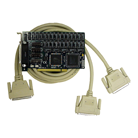
ICS Advent ADIO1600 Series User manual

ADIO1600 Series
Product Manual
MANUAL NUMBER : 00650-004-5D

Errata Sheet
February 2000
Manual Number:
00650-004, ADIO1600 Series Product Manual
Page 3-2: The column headings in Table 3-1 should be “Unipolar (10V) x2 jumper”, “Bipolar (5V) x2 jumper”, “Bipolar (10V) x1
jumper”, and “Software Gain Set” from left to right.

Page - iii
FOREWORD
This product manual provides information to install, operate and or program the referenced product(s)
manufactured or distributed by ICS Advent. The following pages contain information regarding the
warranty and repair policies.
Check our Web site (www.icsadvent.com) for technical information, manuals, and BIOS updates.
Technical assistance is also available at: 800-480-0044 (U.S.) or 858-677-0877 (international).
Customer Comments: If you experience any problems with this manual or just want to provide some
feedback, please send us a message using the online "Service Form" on our Web site (www.icsadvent.com)
under "Support." Detail any errors you find. We will correct the errors or problems as soon as possible and
post the revised manual in our online Support Library. Thank you.
The information in this document is provided for reference only. ICS Advent does not assume any liability
arising from the application or use of the information or products described herein. This document may
contain or reference information and products protected by copyrights or patents and does not convey any
license under the patent rights of ICS Advent, nor the rights of others.
Copyright © 1999, a California Corporation, 6260 Sequence Drive, San Diego, CA92121-4371. ICSAdvent
is a Registered Trademark of ICS Advent. All trademarks and registered trademarks are the property of
their respective owners. All rights reserved. Printed in the United States of America. No part of this publi-
cation may be reproduced, stored in a retrieval system, or transmitted, in any form or by any means, elec-
tronic, mechanical, photocopying, recording , or otherwise, without the prior written permission of the pub-
lisher.

Page - iv
This page intentionally left blank

Page - v
Shipments not in compliance with this Guarantee
and Limited Warranty Return Policy will not be ac-
cepted by ICS Advent.
Guarantee
A thirty day money-back guarantee is provided on all standard products sold. Special order products are
covered by our Limited Warranty, however they may not be returned for refund or credit. EPROMs,
RAM, Flash EPROMs or other forms of solid electronic media are not returnable for credit - but for
replacement only. Extended Warranty available. Consult factory.
Refunds
In order to receive a refund on a product for the purchase price, the product must not have been
damaged by the customer or by the common carrier chosen by the customer to return the goods and
the product must be returned complete (meaning all manuals, software, cables, etc.) within 30 days of
receipt and in an as-new and resalable condition. The Return Proceduremust be followed to assure
prompt refund.
Restocking Charges
Product returned after 30 days, and before 60 days, of the purchase will be subject to a minimum20%
restocking charge and charges for any damaged or missing parts. Products not returned within 60
days of purchase, or products which are not in an as-new and re-saleable condition, are not eligible
for credit return and will be returned to the customer.
Limited Warranty
Effective April 1, 1998, all products carry a 2-year limited warranty. Within two years of purchase,
ICS Advent will repair or replace, at our option, any defective product. ICS Advent will service the
warranty for all standard catalog products for the first two years from the date of shipment.
Please note: The 2-year warranty may not apply to special promotion items. Please consult the factory for
warranty verification.
The limited warranty is void if the product has been subjected to alteration, neglect, misuse, or abuse; if any
repairs have been attempted by anyone other than ICS Advent or its authorized agent; or if the failure is
caused by accident, acts of God, or other causes beyond the control of ICS Advent or the manufacturer.
Neglect, misuse, and abuse shall include any installation, operation, or maintenance of the product other than
in accordance with the user’s manual.
No agent, dealer, distributor, service company, or other party is authorized to change, modify, or extend the
terms of this Limited Warranty in any manner whatsoever. ICS Advent reserves the right to make changes
or improvements in any product without incurring any obligation to similarly alter products previously
purchased.

Page - vi
Return Procedure
For any Guarantee or Limited Warranty return, please contact ICS Advent's Customer Service at
800-480-0044 (U.S.) or 858-677-0877 (international) and obtain a Return Material Authorization (RMA)
Number. All product(s) returned to ICS Advent for service or credit must be accompanied by a Return
MaterialAuthorization (RMA) Number. Freight on all returned items mustbe prepaid by the customer who
is responsible for any loss or damage caused by common carrier in transit. Returns for Warranty must
include a Failure Report for each unit, by serial number(s), as well as a copy of the original invoice showing
date of purchase.
To reduce risk of damage, returns of product must be in an ICSAdvent shipping container. If the original
container has been lost or damaged, new shipping containers may be obtained from ICS Advent Customer
Service at a nominal cost.
ICS Advent owns all parts removed from repaired products. ICS Advent uses new and reconditioned parts
made by various manufacturers in performing warranty repairs and building replacement products.
If ICS Advent repairs or replaces a product, its warranty term is not extended.
ICSAdvent will normally return your replacement or repaired items via Second DayAir. Overnight delivery
or delivery via other carriers is available at an additional charge.
Limitation of Liability
In no event shall ICS Advent be liable for any defect in hardware, software, loss, or inadequacy of data of
any kind, or for any direct, indirect, incidental, or consequential damages in connection with or arising out of
the performance or use of any product furnished hereunder. ICSAdvent liability shall in no event exceed the
purchase price of the product purchased hereunder. The foregoing limitation of liability shall be equally
applicable to any service provided by ICSAdvent or its authorized agent.
Some Sales Items and Customized Systems are not subject to the guarantee and limited warranty.
However in these instances , any deviations will be disclosed prior to sales and noted in the original invoice.
ICS Advent reserves the right to refuse returns or credits on software or special order items.

Page - vii
Advisories
Three types of advisories are used throughout the manual to stress important points or warn of potential
hazards to the user or the system. They are the Note, the Caution, and theWarning. Following is an example
of each type of advisory:
Note: The note is used to present special instruction, or to provide extra information which may
help to simplify the use of the product.
CAUTION!
A Caution is used to alert you to a situation which if ignored may cause injury or
damage equipment.
WARNING!
AWarningisusedtoalertyouofasituationwhichifignoredwillcauseseriousinjury.
Cautions and Warnings are accented with triangular symbols. The exclamation symbol is used in all cautions
and warnings to help alert you to the important instructions. The lightning flash symbol is used on the left
hand side of a caution or a warning if the advisory relates to the presence of voltage which may be of
sufficient magnitude to cause electrical shock.
Use caution when servicing any electrical component. We have tried to identify the areas which may pose
a Caution or Warning condition in this manual; however, ICS Advent does not claim to have covered all
situations which might require the use of a Caution or Warning.
You must refer to the documentation for any component you install into a computer system to ensure proper
precautions and procedures are followed.

Page - viii
This page intentionally left blank

Page - ix
Table of Contents
Chapter 1: Installation...............................................................................................1-1
Backing up the Master Diskette......................................................................................................... 1-1
HardDiskInstallation......................................................................................................................... 1-1
InstallingtheADIO1600Card ............................................................................................................. 1-2
Chapter 2: Functional Description...........................................................................2-1
AnalogInputs..................................................................................................................................... 2-1
Input System Expansion.................................................................................................................... 2-1
DiscreteDigital I/O............................................................................................................................. 2-2
Counter/Timer .................................................................................................................................... 2-2
AnalogOutput ................................................................................................................................... 2-2
Interrupts ........................................................................................................................................... 2-2
ReferenceVoltageandPower Required ............................................................................................. 2-3
Input/OutputConnections .................................................................................................................. 2-3
UtilitySoftware .................................................................................................................................. 2-3
How toremain CECompliant ............................................................................................................. 2-3
Chapter 3: Hardware Configuration and Installation..............................................3-1
OptionSelection ................................................................................................................................ 3-1
MultiplexerConfiguration................................................................................................ 3-1
Unipolar/BipolarRange ................................................................................................... 3-1
ExternalConditioningModuleSupport ........................................................................... 3-1
InputVoltage Range ....................................................................................................... 3-1
AnalogOutput VoltageRange ........................................................................................ 3-2
Counter/Timer ................................................................................................................ 3-4
Clock Frequency Select ................................................................................................. 3-4
Selecting and Setting the BaseAddress............................................................................................ 3-4
Selecting a BaseAddress .............................................................................................. 3-4
Setting the BaseAddress............................................................................................... 3-6
Using the Setup Program to Set the BaseAddress ....................................................... 3-6
CalibrationandTest ........................................................................................................................... 3-7
Chapter 4: Software ..................................................................................................4-1
SoftwareProvided .............................................................................................................................. 4-1
SamplePrograms.............................................................................................................................. 4-1
ADIO1600CDMSoftwareDriverReference ........................................................................................ 4-1

Page - x
CardDriverModules(CDM)................................................................................................................ 4-2
UsingtheCDMDriver ..................................................................................................... 4-5
ProgrammingwiththeCDMDriver.................................................................................. 4-6
MultiplexerDriver Module (MDM) ....................................................................................................... 4-6
UsingtheMDMDriver .................................................................................................... 4-7
CDMDriverErrorList .................................................................................................................. 4-8
VISUALBASICUTILITYDRIVER ........................................................................................................ 4-9
InPortb ........................................................................................................................... 4-9
InPort ............................................................................................................................. 4-9
OutPortb ........................................................................................................................ 4-9
OutPort .......................................................................................................................... 4-9
Peek .............................................................................................................................. 4-9
Poke .............................................................................................................................4-10
Chapter 5: Programming ..........................................................................................5-1
ADIO1600RegisterAddressMap....................................................................................................... 5-1
RegisterDefinitions............................................................................................................................ 5-2
CardStatusand Clear Interrupt ................................................................................................... 5-2
Startand Command Registers .................................................................................................... 5-3
A/DRegisters ............................................................................................................................. 5-3
DigitalI/O.................................................................................................................................... 5-4
Analog Outputs ........................................................................................................................... 5-9
Counter/TimerRegisters.............................................................................................................5-10
Chapter 6: A/D Converter Applications....................................................................6-1
ConnectingAnalogInputs .................................................................................................................. 6-1
CommentsonNoise Interference ....................................................................................................... 6-1
InputRangeandResolutionSpecifications......................................................................................... 6-2
CurrentMeasurements ...................................................................................................................... 6-2
MeasuringLargeVoltages.................................................................................................................. 6-2
Precautions-Noise,GroundLoops,andOverloads ........................................................................... 6-3
Chapter 7: Programmable Interval Timer ................................................................7-1
OperationalModes............................................................................................................................. 7-1
Programming ..................................................................................................................................... 7-2
ReadingandLoading the Counters .................................................................................................... 7-3
ProgrammingExamples .................................................................................................................... 7-5
MeasuringFrequencyandPeriod....................................................................................................... 7-5
GeneratingTimeDelays .................................................................................................................... 7-6
GeneratingInterruptsWiththeCounter/Timer .................................................................................... 7-6
Chapter 8: D/A Converters........................................................................................8-1
Programming .............................................................................................................................. 8-1

Page - xi
Chapter 9: Specifications .........................................................................................9-1
AnalogInputs.............................................................................................................................. 9-1
A/DSpecifications....................................................................................................................... 9-1
SampleandHoldAmplifier(Internal)............................................................................................ 9-2
D/ASpecifications ....................................................................................................................... 9-2
DigitalI/O.................................................................................................................................... 9-3
InterruptChannel......................................................................................................................... 9-3
ProgrammableTimer ................................................................................................................... 9-3
Environmental ............................................................................................................................. 9-4
Appendix A: Linearization ....................................................................................... A-1
Appendix B: Cabling and Connector Information ................................................. B-1
ADIO1600 PrimaryConnector PinAssignments................................................................................. B-1
ADIO1600Auxiliary Connector PinAssignments................................................................................ B-3
ADIO1600To1-8 MultiplexerCableAdapterAssembly ...................................................................... B-5
ADIO1600ToAdditional MultiplexersCableAdapterAssembly .......................................................... B-7
Appendix C: Basic Integer Variable Storage.......................................................... C-1
CE Declaration of Conformity ......................................................................................1
List of Figures
Figure2-1:ADIO1600BlockDiagram ....................................................................................................... 2-4
Figure 3-1:Option SelectionMap ............................................................................................................. 3-3
List of Tables
Table3-1: VoltageRange ........................................................................................................................ 3-2
Table3-2: OutputVoltageRange ............................................................................................................. 3-2
Table3-3: StandardBaseAddressAssignments ...................................................................................... 3-5
Table: 3-5: BaseAddress Example ......................................................................................................... 3-6
Table B-1: Connector PinAssignments ................................................................................................... B-2
Table B-2: Auxiliary PinAssignments ...................................................................................................... B-4
TableB-3: MultiplexerCableAdapterAssembly ...................................................................................... B-6
TableB-4: Additional MultipleCableAdapterAssembly ........................................................................... B-8
Current Revision 5D
December 2000

Chapter 1: Installation
Manual Number: 00650-004-5 Page 1-1
Chapter 1: Installation
Backing up the Master Diskette
The software provided with the ADIO1600 is on a 3 1/2" DOS diskette. As with any software
package, you should make backup copies for everyday use and place your original master diskette
in a safe location.
The easiest way to make a backup copy is to use the DOS DISKCOPY utility.
In a single drive system the command is:
DISKCOPY A: A:
You will need to swap disks as requested by the system.
In a two-disk system the command is:
DISKCOPY A: B:
This will copy the contents of the master disk in drive A to the backup disk in drive B.
Hard Disk Installation
The files contained on the master diskette may also be copied onto your hard disk. To do this,
perform the following:
1.) Place the master diskette into a floppy drive.
2.) Change the active drive to the drive that has the master diskette installed. For example, if the
diskette is in drive A, type A:.
3.) Type INSTALL and follow the screen prompts.
Files contained on the disk are stored in separate directories. These are:
ROOT DIRECTORY: Contains the FINDBASE program that will help you to decide what
base address to use for the card. Also contains the A1216EST.EXE
setup and calibration programs, and POLY.EXE, the linearization
polynomial program.
PSAMPLES: Contains Pascal samples and the Pascal-linkable driver.
CSAMPLES: Contains "C" samples and the C-linkable driver.
BSAMPLES: Contains the QuickBASIC samples as well as the binary and
linkable drivers.

Manual Number: 00650-004-5Page 1-2
ADIO1600 Manual
VBACCES: VisualBASIC utility driver that includes PEEK and POKE statements
for reading and writing RAM as well as OUTPORT and INPORT
for reading and writing port I/O. The driver is in the form of a DLL
and allows you to access hardware as if the language was designed
for it when you use VisualBASIC for Windows. (Support for VisualBASIC
4.x is not yet available).
Installing the ADIO1600 Card
The following procedure will show you how to install the ADIO1600 inside the computer.
1) Ensure that all options have been set as described in the OPTION SELECTION chapter. Be
sure to pay close attention to base address selection.
2) Turn off the power switch of your computer and remove the power cords from the wall outlet.
CAUTION
Failure to remove power from the computer could result in electrical shock, or damage to your
computer system.
3) Remove the computer cover.
4) Locate an unused full length slot, and remove a blank I/O backplate.
Optionally remove a second backplate for the auxiliary digital I/O port.
5) Insert the card in the slot, and install the I/O back plate screw.
6) Install the auxiliary connector backplate connect via a ribbon cable extension from the 40-pin
IDC connector.
7) Inspect the installation for proper fit and seating of the card.
8) Replace the back cover.
9) Reapply power to the computer.
10) Run the A1216EST setup program to test the card, and optionally calibrate.

Chapter 2: Functional Description
Manual Number: 00650-004-5 Page 2-1
Chapter 2: Functional Description
The ADIO1600 is a multifunction high-speed analog/digital I/O card for use in IBM Personal Com-
puters. It is a 3/4 length card that can be installed in an expansion slot of an IBM PC/XT/AT and
compatible computers. With this card installed, the computer can be used as a precision data
acquisition and control system or as a signal analysis instrument. The following paragraphs describe
functions provided by this card.
Analog Inputs
The card accepts up to eight differential or 16 single-ended analog input channels. Inputs are
protected against overvoltages (by the internal multiplexer diodes (rated at 20mA maximum) con-
nected to the + and - of the power supply. An external series 1K resistor is suggested if serious
overvoltage or static problems exist. As an alternative, a factory installed special multiplexer will
extend overvoltage protection further. The channel input configuration is jumper selectable on the
card providing a choice between sixteen single-ended channels or eight differential channels. In the
latter case, common mode rejection ratio is a minimum 80 dB and common mode voltage range is
±12V.
Inputs are amplified by an instrumentation amplifier with a combination of switch selectable gains of
1 or 2, and software selectable gains of 1000, 100, 10 and 1 to provide voltage ranges of ±0.005,
±0.01, ±0.05, ±0.1, ±0.5, ±1 , ±5 and ±10 volts bipolar and 0.01, 0.1, 1, and 10 volts unipolar (gain
switch must be set to x2).
The ADIO1600 uses an industry standard 12-bit successive-approximation analog-to-digital con-
verter (A/D) with a sample and hold amplifier input. Under the right conditions, max throughput is
100,000 conversions per second.
A/D conversions may be initiated in any one of three ways: (a) by software command, (b) by
on-board programmable timer, or (c) by direct external trigger. In turn, data may be transferred to
the computer by either of two software selectable methods: (a) by polling for end of BUSY or (b) by
end of BUSY interrupt.
Input System Expansion
The card can be used with up to 8 external AT16-P analog input expansion cards. The ADIO1600
does not support the programmable gain capability of the AT16-P and requires jumper changes on
the AT16-P to support manual gain. Each AT16-P card provides capability for 16 differential inputs
and, thus, there can be up to a maximum of 128 inputs per combination of AT16-Ps and ADIO1600.
The first AT16-P is connected to the ADIO1600 by a special cable adapter and ribbon cable, any
additional AT16-P cards are daisy-chained to each other by ribbon cables. Cabling information is
provided in Appendix B.

Manual Number: 00650-004-5Page 2-2
ADIO1600 Manual
Discrete Digital I/O
Four bits of TTL/CMOS-compatible digital input capability are provided at the mounting panel con-
nector. Twenty-four additional digital I/O bits are available at the auxiliary connector on the board
which are available at a backplate connector via a ribbon cable extension from the auxiliary connec-
tor. Digital inputs IP0 and IP2 have dual uses. Input IP0 provides an external trigger for the A/D.
Input IP2 is also the gate input for Counter/Timer 0. Note that the use of the Counter prevents use
of IP2.
Four bits of digital output are available with powerful LSTTL logic level load drive capability. Dis-
crete outputs OP0 through OP3 provide multiplexer addressing for input expansion card use, as
described in the INPUT SYSTEM EXPANSION section, or as separate digital outputs.
Additionally, OP0 through OP3 can be individually software configured for use as additional TTL/
CMOS-compatible digital inputs, providing a total of up to eight Digital Inputs at the rear panel
connector.
The auxiliary digital I/O port is from a 8255 Programmable Peripheral Interface which provides 24-
bits of bi-directional input/output bits configured as two sets of 8-bit and two sets of 4-bit digital
input/output ports. This port is extended using a ribbon cable from the side of the board to a 37-pin
connector on a rear mounting bracket.
Counter/Timer
The ADIO1600 contains a type 8254 counter/timer which has three 16-bit programmable down
counters. Counter/Timer #0 is enabled by a digital input (IP2) and uses either the internal 1MHz
clock or an external clock of up to 10 MHZ. Counter/Timers #1 and #2 are concatenated and form
a 32-bit counter/timer for timed A/D trigger pulses and/or external frequency generation. The dual
counter/timer can be enabled by program control and clocked by a 1 MHZ on-board crystal oscilla-
tor source. Counter #2 may be set to generate an interrupt request (IRQ) upon completing a
counter period.
Counter/Timer 0 and Counter/Timers 1 and 2 can be set up for event counting, frequency or period
measurements, and pulse or wave form generation. Also, Counter/Timers 1 and 2 can be pro-
grammed to initiate A/D conversions. See the PROGRAMMABLE INTERVAL TIMER sec-
tion of this manual for a description of ways that the type 8254 counter/timer chip can be used.
Analog Output
The ADIO1600 has two 12-bit digital-to-analog converters (D/A) connected to output drivers ca-
pable of providing 5 mA current drive. By selecting on-board jumpers outputs of 0-5 VDC, 0-10
VDC, 0-2.5 VDC, ±2.5 VDC, ±5VDC, or ±10 VDC are possible.
Interrupts
Interrupts can be initiated by completion of an A/D conversion or Counter timeout if programmed by
software. Interrupt levels 2-7, 10-12, 14 and 15 are selectable via jumpers.

Chapter 2: Functional Description
Manual Number: 00650-004-5 Page 2-3
Reference Voltage and Power Required
A +5.0 volt (±0.05) reference voltage is used internally for the A/D converter and the D/A analog
outputs. The ADIO1600 requires only +5VDC from the computer power supply. An on-board
DC-DC converter translates the 5VDC to low noise, isolated ±15VDC for the precision analog
circuitry.
Input/Output Connections
External connections are made through a standard 37-pin male D connector located at the rear of
the computer and an auxiliary 40-pin IDC connector on the board. External multiplexers or signal
conditioning hardware, such as our AT16-P or LVDT8-P, are connected using special cabling as
described in APPENDIX B.
Utility Software
Utility software is provided on diskette with the ADIO1600 card. This software includes an illus-
trated setup and calibration program, and a universal software driver for any language that supports
the Pascal calling convention (such as QuickBASIC, C, and Pascal), and sample programs. Addi-
tionally, a utility driver for use with VisualBASIC for Windows is provided.
How to remain CE Compliant
In order for machines to remain CE compliant, only CE compliant parts may be used. To keep a
chassis compliant it must contain only compliant cards, and for cards to remain compliant they must
be used in compliant chassis. Any modifications made to the equipment may affect the CE compli-
ance standards and should not be done unless approved in writing by ICS Advent.
The Model ADIO1600 is designed to be CE Compliant when used in an CE compliant chassis.
Maintaining CE Compliance also requires proper cabling and termination techniques. The user is
advised to follow proper cabling techniques from sensor to interface to ensure a complete CE
Compliant system. ICS Advent does not offer engineering services for designing cabling or termina-
tion systems. Although ICS Advent offers accessory cables and termination panels, it is the user's
responsibility to ensure they are installed with proper shielding to maintain CE Compliance.

Manual Number: 00650-004-5Page 2-4
ADIO1600 Manual
Figure 2-1: ADIO1600 Block Diagram

Chapter 3: Hardware Configuration and Installation
Manual Number: 00650-004-5 Page 3-1
Chapter 3: Hardware Configuration and Installation
Option Selection
Many of the ADIO1600 card features are selected by hardware jumpers or switches. At least one
of each of the option categories must be selected if the card is to operate correctly. The A1216EST
setup program provided on diskette with the card provides menu-driven pictorial presentations to
help you quickly set up the card.
You may also refer to FIGURE 3-1: OPTION SELECTION MAP, and the following sections to
set up the card. The card need not be plugged into the computer at this time.
Multiplexer Configuration
Select the desired A/D input multiplexer configuration by moving JP8 and JP9 jumpers to the appro-
priate position:
8-Channel Differential Input = DIFposition
16-Channel Single-Ended Input = SEposition
Unipolar/Bipolar Range
In the unipolar mode, inputs can be positive only; i.e., ranges from zero volts to some positive
voltage. (The maximum voltage span in the unipolar mode is 10V.) In the bipolar mode, inputs can
be between positive and negative full scale limits. In the unipolar range, the JP3 Gain jumper must
be in the x2 position. Select the unipolar or bipolar range using jumper JP4 located in the upper right
hand corner of the card near the I/O connector:
Unipolar= UNIP position
Bipolar = BIP position
The two's complement jumper, JP5, is an option for bipolar ranges which changes the data format
for both the ADC analog input and DAC analog output data registors.
External Conditioning Module Support
AT16-P jumper JP10 sets the internal programmable gain amplifier to a unity gain to simplify soft-
ware programming. The ADIO1600 supports external conditioning modules, such as the AT16-P
series, with MDM driver modules as described in the SOFTWARE SECTION. Additionally, extra
grounds are available on pins 18 (Channel 8) and 11 (Channel 15) by installing respective AT16-P
jumpers JP6 and JP7.
Input Voltage Range
Input voltage range is selected by the combination of the software gain setting and the span of the
input range selected by on-board jumpers. The following table relates voltage range to the gain
required.

Manual Number: 00650-004-5Page 3-2
ADIO1600 Manual
egnaRtupnIderiseD erawtfoS teSniaG
RALOPINU repmuj2x)V01( )V5(RALOPIB repmuj2x )V02(RALOPIB repmuj1x
V01-0V5±V01±1
V1-0V5.0±V1±01
V1.0-0V50.0±V1.0±001
V10.0-0V500.0±V10.0±0001
Table 3-1: Voltage Range
Note: The ADIO1600 is best configured for ±5V inputs for compatibility ith external modules
using this range. Other ranges are possible ith proper consideration to the limits of the external
module and ADIO1600. The biploar range is also the preferred range for data formatted in t o's
complement and should be used if the JP5 t o's complement data option jumper is installed. If the
t o's complement data option is enabled, it ill also change the DAC output data registor into the
t o's complement data format.
Analog Output Voltage Range
Output voltage range is selected manually by on-board s itches. Each analog output has a three
s itch group that selects the options. S itch S2 is for DAC0, and S3 is for DAC1, refer to the
OPTION SELECTION MAP or the A1216EST setup soft are for their locations. The t o's
complement data format jumper, JP5, also changes the data format of the DAC registers and must
be considered in its use. Position 1 on each s itch selects bet een unipolar or bipolar operation.
Position 2 and 3 select the voltage range, as described in the follo ing table:
egnaRegatloVtuptuOderiseD
3Sdna2SsehctiwS
egnaRegatloV2noitisoP3noitisoP
V5.2FFONO
V5FFOFFO
V01NOFFO
Table 3-2: Output Voltage Range

Chapter 3: Hardware Configuration and Installation
Manual Number: 00650-004-5 Page 3-3
Figure 3-1: Option Selection Map
Connectors:
J1 - 37 Pin Male D Connector (Primary Analog) on rear panel backplate
J2 - 40 Pin Male IDC Ribbon Cable Connector (Aux Digital I/O) connects to second rear panel connector
Switches:
S1 - Base Address Selection A5-A9
S2 - DAC0 Output options
S3 - DAC1 Output options
Option Jumpers:
JP1 - End of Conversion IRQ selection IRQ2-7
JP2 - End of Conversion IRQ selection IRQ10-15
JP3 - Analog Converter Input Range X1, X2
JP4 - Analog Input Polarity - Unipolar or Bipolar
JP5 - DAC/ADC Data Format - 2s Complement if installed, Offset Binary coding if removed.
JP6 - AT16-P Compatibility Jumper - Grounds Channel 8 (pin 18) Input when installed.
JP7 - AT16-P Compatibility Jumper - Grounds Channel 15 (pin 11) Input when installed.
JP8 - Selects Single Ended/Differential Analog Input (Must be set the same as JP9 below)
JP9 - Selects Single Ended/Differential Analog Input (Must be set the same as JP8 above)
JP10 - AT16-P Compatibility Jumper - Sets PGA gain to x1
DAC Analog Output ADC Analog Input
RP1 - DAC0 Zero Adj RP5 - Output Offset
RP2 - DAC0 Span Adj RP6 - Fullscale Adjust
RP3 - DAC1 Zero Adj RP7 - Input Offset
RP4 - DAC1 Span Adj RP8 - Unipolar Offset
Calibration Potentiometers
Other ICS Advent PCI Card manuals

ICS Advent
ICS Advent WDT1000-P User manual

ICS Advent
ICS Advent PCI-32REL User manual

ICS Advent
ICS Advent WINCOMM8/C User manual

ICS Advent
ICS Advent RB-24 User manual

ICS Advent
ICS Advent AOB8/16 User manual

ICS Advent
ICS Advent PCI-ICOM485/4 User manual

ICS Advent
ICS Advent DUAL232/AT Series User manual

ICS Advent
ICS Advent PCI-DIO48 Series User manual

ICS Advent
ICS Advent ULTRA-485 User manual

ICS Advent
ICS Advent PB751-AT User manual