Notes on the operating instr ctions
- The operating instr ctions are in-
tended for specialist workers and
trained personnel.
- Before each stage of work, read the
relevant notes and warnings care-
f lly, and keep to the seq ence as
stated.
- Pay partic lar attention to the sec-
tion on ”General safety warnings”.
If yo have any problems or q estions,
please contact yo r s pplier or
cons lt the company MARIANNE
MAYER, ELECTRONISCHE SCHAL-
TUNGEN directly.
1.
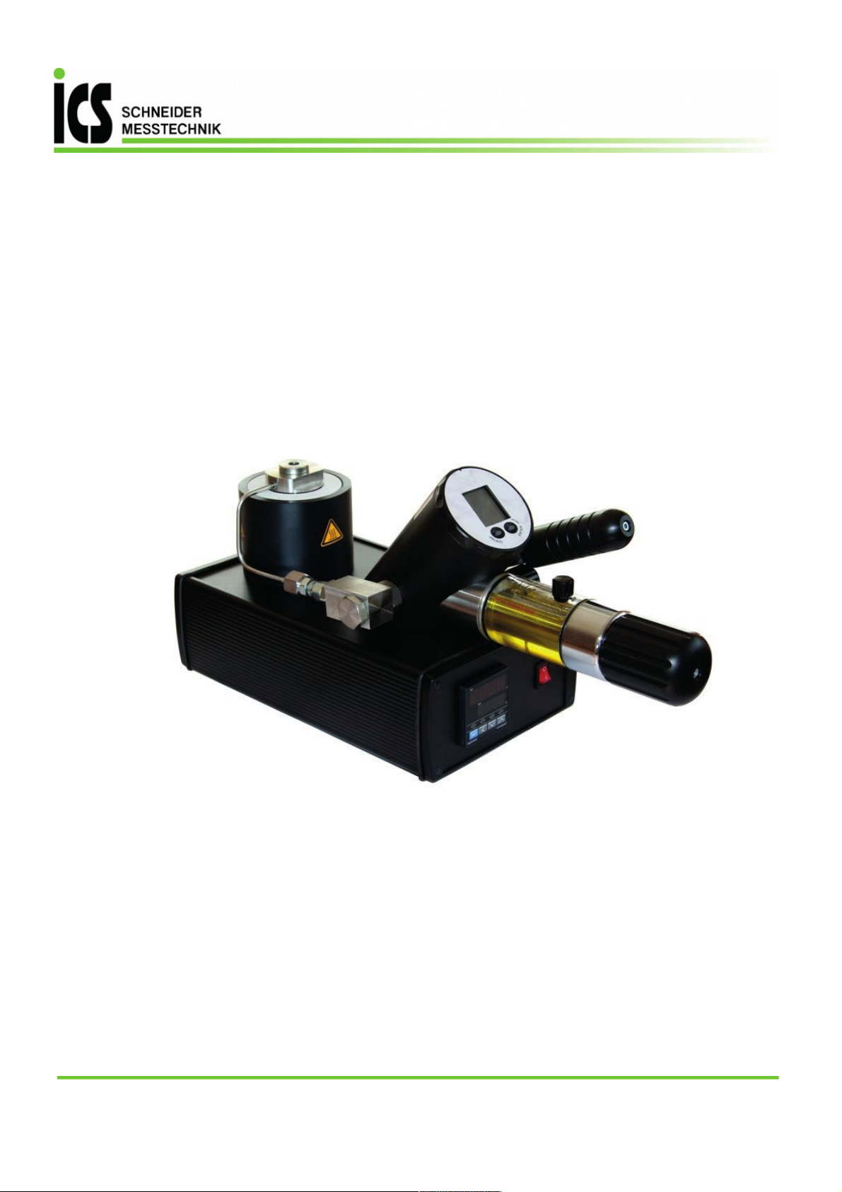
Description of the device
General description
The high press re calibrator enables
press re to be generated by means of
the integrated press re p mp, p to
700 bar relative.
The meas rement technology incor-
porated into this device allows ac-
c rate meas rement and doc men-
tation of the characteristic of a test
object that is connected to it. The
meas red press re progression can
be displayed, eval ated and saved
with a comp ter monitoring program
(CCS30).
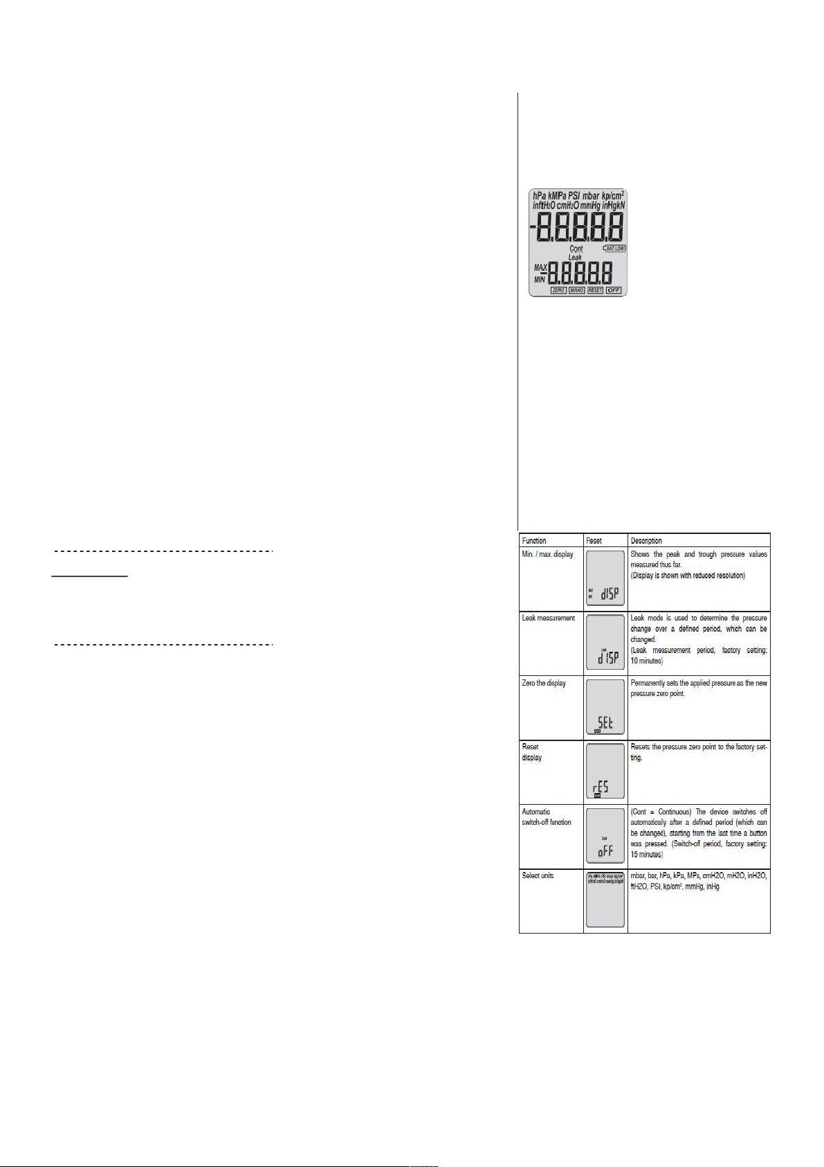
The calibrator is operated with the
two f nction b ttons SELECT and
ENTER, located directly below
the display. The calibrator itself is
powered by a 3,0 V battery.
Copyright
For copyright reaons this operating
man al may only be sed for inho se
p rposes.
Any reprod ction, even in part and for
inho se p rposes, req ires the assent
by Messrs
Also, any distrib tion to third parties is
prohibited for competitive reasons.
Commissioning
A press re-resistant connection for
the test object is req ired in order to
se the high press re calibrator. The
press re connection for the test object
is already screwed to the press re
distrib tor of the high press re calibra-
tor so that it is press re resistant when
it leaves the factory, and it m st not be
dismantled.
Recommended torq e for the test
object press re connection: 30 Nm
IMPORTANT!
Nothing m st adhere to the s rface of
the test object (no oil, grease, water,
etc). Imp rities co ld pass tro gh the
adapter to reach the high press re
calibrator and damage it.
Overpress re
If the press re exceeds the meas ring
range by more than 20%, the meas r-
ing cell or the mechanism of the high
press re calibrator may be destroyed
Recalibration
The recalibration cycle depends on
the conditions of se. Recommended
recalibration cycle: 1 year.
Intended se
The high press re calibrator may
only be sed to generate press re
with the type HLP 22 BP hydra lic oil
that is s pplied with the prod ct. Use
of the calibrator with other media will
damage it. The operational safety
of the device s pplied is g aranteed
only if it is sed as intended. The limit
val es as stated (see page 9: ”Tech-
nical data”) m st never be exceeded.
Before installing the high press re
calibrator, check that it is s itable for
yo r applications
2.
General safety warnings
The c rrent national reg lations on
accident prevention and
workplacesafety m st be followed
whenever work is carried o t.
Internal reg lations iss ed by the
operator m st
be followed, even if
they are not mentioned in these
instr ctions.
Never se the high press re calibra-
tor together with an external press re
so rce.
Do not remove any connected compo-
nents (e.g. test objects) when the high
press re calibrator is nder press re.
Open the screwed sealing pl g before
removing parts.
Do se Teflon tape to seal the
press re connection caref l. Resid es
of
Teflon tape co ld penetrate the
high- press re calibrator and damage
it.
Only se the adapters and seals that
are available as accessories.
Do not store the calibrator nder pres-
s re: only store the high press re cali-
brator with the drain valve open.
Avoid the action of force of any kind
on the high press re calibrator and its
operating controls.
Do not se high press re calibrators if
they are damaged or fa lty.
4