ICS CWS-200 User manual

© 2010 ICS, Blount International Inc. Specications are subject to change without notice. REV0810 F/N 542025
CWS-200
CHAIN WALL SAW
OPERATOR’S MANUAL


© 2010 ICS, Blount International Inc. Specications are subject to change without notice. REV0810 F/N 542025
TITLECWS-200 OPERATOR’S MANUAL
3
TABLE OF CONTENTS
PRIMARY COMPONENTS 4
SYMBOLS & LABELS 5
SAFETY 6
TECHNICAL SPECIFICATIONS 8
MACHINE REFERENCES & SET-UP 9
OPERATION 13
MAINTENANCE 17
TROUBLESHOOTING 19
INTRODUCTION
This manual outlines the operation and basic maintenance of the ICS® CWS-200 Chain Wall Saw.
The CWS-200 combines ICS® Diamond Chain Technology (DCT™) with a mechanized, track-
mounted and hydraulic powered design for use by Professional Sawing & Drilling Contractors.
To achieve the maximum benefit from your machine and to ensure safe operation, please read this
manual thoroughly and periodically review the safety instructions.

© 2010 ICS, Blount International Inc. Specications are subject to change without notice. REV0810 F/N 542025
TITLE CWS-200 OPERATOR’S MANUAL
4
WARNING
• Do NOT operate the machine without side cover or guard enclosure installed.
• Do NOT tension chain, install or remove guide bar, chain or side cover without powering off hydraulic supply.
• Failure to observe these precautions can result in serious injury.
F/N 541814
• Do NOT exceed hydraulic flow of 25
gpm (95 lpm) at 2500 psi (172.5 bar)
hydraulic pressure.
• Do NOT operate the machine if the
work piece, rail and/or machine are
not properly supported and secured.
• Do NOT operate with machine
directly over head.
• ALWAYS disengage the machine
from the rail before repositioning or
removing.
• Fluids escaping under pressure can
penetrate the skin.
• Failure to observe these precautions
can result in serious injury.
WARNING
F/N 541813
Valve Knob must be in
center “OFF” position
before powering on
hydraulic supply.
WARNING
F/N 541812
PRIMARY COMPONENTS
PRIMARY MACHINE COMPONENTS
WARNING LABEL LOCATIONS
WATER SUPPLY
HANDLE FRAME
GUARD CLAMP BRACKETS
GUARD ENCLOSURE
VALVE KNOB
TRAVERSE
CARRIAGE SIDE COVERSIDE COVER BASE
HYDRAULIC HOSE
CONNECTIONS
ROTATION CONTROLS
TRAVERSE CONTROLS
1
2
3

© 2010 ICS, Blount International Inc. Specications are subject to change without notice. REV0810 F/N 542025
TITLECWS-200 OPERATOR’S MANUAL
5
SYMBOLS & LABELS
THE FOLLOWING SYMBOLS AND DEFINITIONS ARE FOUND THROUGHOUT THIS MANUAL AND
ARE DESIGNED TO MAKE YOU AWARE OF POTENTIAL HAZARDS OR UNSAFE PRACTICES
A potentially hazardous situation exists which, if not avoided,
could result in death or serious injury.
A potentially hazardous situation exists which, if not avoided,
may result in minor or moderate injury or property damage.
THE FOLLOWING SYMBOLS & LABELS MAY BE FOUND IN THIS MANUAL OR ON THE MACHINE
Read the operator’s manual carefully and understand the
contents before you use this equipment.
Always use:
• Protective helmet
• Ear protection
• Protective glasses or full face protection
Wear hand protection
WARNING
CAUTION
Valve Knob must be in
center “OFF” position
before powering on
hydraulic supply.
WARNING
F/N 541812
• Do NOT exceed hydraulic flow of 25
gpm (95 lpm) at 2500 psi (172.5 bar)
hydraulic pressure.
• Do NOT operate the machine if the
work piece, rail and/or machine are
not properly supported and secured.
• Do NOT operate with machine
directly over head.
• ALWAYS disengage the machine
from the rail before repositioning or
removing.
• Fluids escaping under pressure can
penetrate the skin.
• Failure to observe these precautions
can result in serious injury.
WARNING
F/N 541813
WARNING
• Do NOT operate the machine without side cover or guard enclosure installed.
• Do NOT tension chain, install or remove guide bar, chain or side cover without powering off hydraulic supply.
• Failure to observe these precautions can result in serious injury.F/N 541814
1 2
3

© 2010 ICS, Blount International Inc. Specications are subject to change without notice. REV0810 F/N 542025
TITLE CWS-200 OPERATOR’S MANUAL
6
SAFETY
WARNING
THE FOLLOWING SYMBOL APPLIES TO ALL THE ITEMS LISTED ON THIS PAGE
A potentially hazardous situation exists which, if not avoided,
could result in death or serious injury.
• Do NOT operate the machine with loose, modified, missing or damaged side cover, side cover
base or guard enclosure. (To perform flush cutting, temporary removal of the side cover and
guard enclosure may be necessary.)
• ALWAYS use the extended speed wrench to operate the rotation and traverse controls.
• Do NOT operate the machine with modified, missing or damaged components. Prior to
operation, check that the machine is in full working order.
• Do NOT exceed hydraulic flow of 25 gpm (95 lpm) at 2500 psi (172.5 bar) hydraulic pressure.
• Do NOT power on the hydraulic supply without making sure the Valve Knob is in the center
“OFF” position.
• Do NOT tension chain, install or remove guide bar, diamond chain or side cover without
powering off hydraulic supply.
• ALWAYS disconnect the hydraulic hoses from the machine if not in use and prior to
performing maintenance or service.
• Do NOT operate the machine if the work piece, rail and/or machine are not properly
supported and secured.
• Do NOT operate with the machine directly over head.
• ALWAYS disengage the machine from the rail before repositioning or removing.
• Fluid escaping under pressure can penetrate the skin.

© 2010 ICS, Blount International Inc. Specications are subject to change without notice. REV0810 F/N 542025
TITLECWS-200 OPERATOR’S MANUAL
7
SAFETY
CAUTION
THE FOLLOWING SYMBOL APPLIES TO ALL ITEMS LISTED ON THIS PAGE
A potentially hazardous situation exists which, if not avoided,
may result in minor or moderate injury or property damage.
• ALWAYS closely inspect the machine for worn, damaged or broken components that may
have occurred during use or due to an accidental impact or drop.
• Do NOT operate the machine if the diamond chain, guide bar and/or drive sprocket show
evidence of significant wear or damage. Replace if necessary.
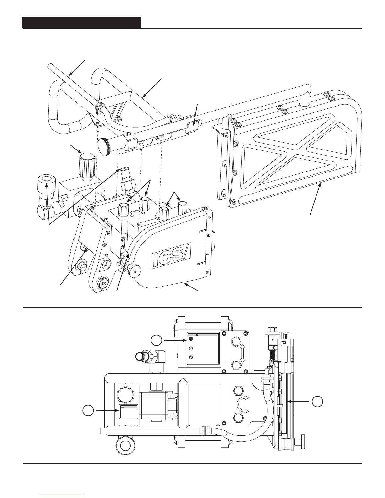
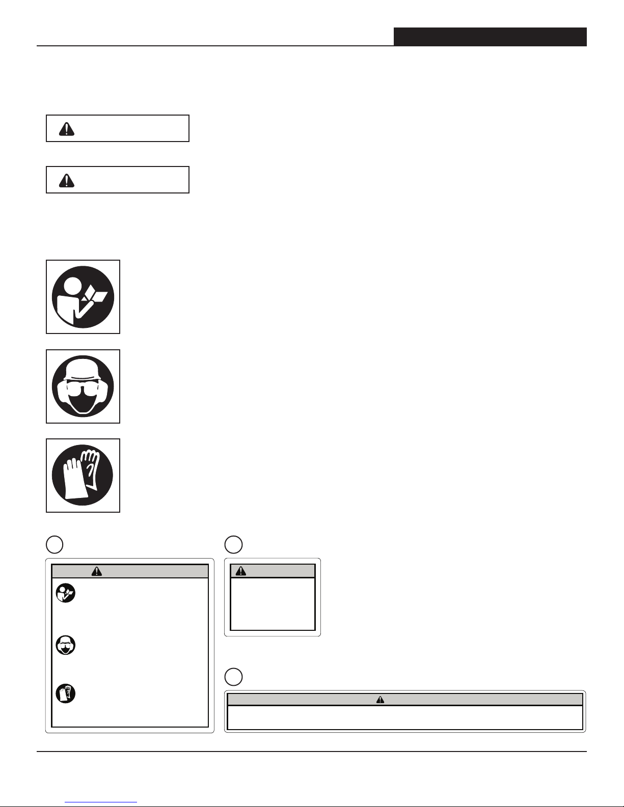
• ALWAYS use genuine ICS® repair and replacement parts.
• Do NOT modify the machine or use components from other machines.
• ALWAYS ensure at least 20 psi (1.5 bar) water pressure is supplied to the machine.
• Avoid inserting the diamond chain into a slot narrower than the diamond segments.
Ref: The diamond segments used for the CWS-200 are .245" (6.45 mm) wide.
• ALWAYS complete the pre-cut checklist prior to each use (refer to p. 12).
• ALWAYS wear protective clothing, including hard hat, eye protection, hearing protection, and
appropriate gloves and boots.
• Avoid loose fitting clothing.
• NEVER use equipment that is poorly maintained or not functioning properly.
• ALWAYS operate and/or lift the machine with solid footing and proper positioning.
• Remove or control slurry to prevent slippery conditions in the working area.
• ALWAYS check for and remove any obstructions (plumbing, electrical conduit, air ducts, etc.)
that may interfere with the cut.
• Do NOT allow unnecessary bystanders within the working area.
• Set up a well-marked, properly organized working area with a roped boundary and clear
signs.
• ALWAYS ensure adequate ventilation when working in an enclosed area.

© 2010 ICS, Blount International Inc. Specications are subject to change without notice. REV0810 F/N 542025
TITLE CWS-200 OPERATOR’S MANUAL
8
TECHNICAL SPECIFICATIONS
CWS-200 SPECIFICATIONS
BASE MACHINE W/OUT
BAR, CHAIN, & GUARD 75 lbs (34 kg)
12" GUARD 9 lbs (4 kg)
18" GUARD 11 lbs (5 kg)
HYDRAULIC SUPPLY 25 gpm (95 lpm) @ 2,500 psi (172.5 bar)
TORQUE 284 in-lbs (32 Nm)
HORSEPOWER 36.5 hp (27.2 kW)
WATER SUPPLY Minimum 20 psi (1.5 bar)
OPERATING SPEED 8,100 rpm (avg. free running)

© 2010 ICS, Blount International Inc. Specications are subject to change without notice. REV0810 F/N 542025
TITLECWS-200 OPERATOR’S MANUAL
9
REFERENCES & SET-UP
STEP 3
Slide the guide bar between the bar
pad plate and the clamp plate until
the tail of the guide bar engages
with the alignment pins.
STEP 1
Loosen the side cover knob and
pivot the clamp stud forward to
disengage from the side cover base.
Remove the side cover.
STEP 4
Turn the tensioning knob counter
clockwise until the guide bar nearly
contacts the drive sprocket.
GUIDEBAR AND DIAMOND CHAIN INSTALLATION
STEP 2
Loosen the guide bar clamp nut a
couple of turns.

© 2010 ICS, Blount International Inc. Specications are subject to change without notice. REV0810 F/N 542025
TITLE CWS-200 OPERATOR’S MANUAL
10
REFERENCES & SET-UP
STEP 5
Mount the chain on the guide bar
starting at the drive sprocket and
continuing over the guide bar nose.
STEP 7
Firmly tighten the guide bar clamp
nut using a 3/4" open-ended
wrench.
STEP 6
Ensure all of the drivelinks are
engaged in the guide bar groove
and turn the tensioning knob
clockwise to tension the chain. Do
not over tension the chain. The
chain should be snug, but should be
able to be pulled around the guide
bar by hand.
STEP 8
Re-install the side cover, first by
orienting the side cover at a slight
forward leading angle and inserting
the side cover hinge bar on to the
side cover base locating pins. Then
rotate the side cover down on to the
side cover base. Pivot the clamp
stud rearward allowing it to ‘hook’
under the side cover base. Firmly
tighten the side cover knob by hand.
Before operation, ensure the side
cover is properly secured.
GUIDEBAR AND DIAMOND CHAIN INSTALLATION

© 2010 ICS, Blount International Inc. Specications are subject to change without notice. REV0810 F/N 542025
TITLECWS-200 OPERATOR’S MANUAL
11
STEP 3
To adjust the machine to the
underside of the rail, loosen the cap
screws clamping the (4) retractable
rollers to the traverse carriage. Turn
the entire body of the retractable
rollers until making light contact
with the underside of the rail. After
completing the adjustment, retighten
the cap screws.
STEP 1
Prior to installing the machine
on the rail, ensure the (4) lower
retractable rollers on the traverse
carriage are in the outward position.
Place the machine on the rail and
while maintaining full support, push
the (4) lower retractable rollers
inward to secure the machine to
the rail.
STEP 2
To adjust the machine to the side
of the rail, loosen the cap screws
securing the (2) adjustable side
rollers on the traverse carriage
(motor side). Using an open-ended
wrench turn the adjustable side
rollers until making light contact
with the rail. After completing the
adjustment, retighten the cap
screws.
REFERENCES & SET-UP
MACHINE FIT-UP TO 360 RAIL
ALWAYS ensure the machine is
adequately secured to the rail
before operation. The machine
should travel freely along the rail
with use of the traverse controls.
Play between the machine and
the rail should be minimal, but
still allow for easy installation and
removal.

© 2010 ICS, Blount International Inc. Specications are subject to change without notice. REV0810 F/N 542025
TITLE CWS-200 OPERATOR’S MANUAL
12
STEP 3
ALWAYS ensure the guard
enclosure is positioned and oriented
properly to the guide bar during
operation.
STEP 1
To install the guard enclosure on the
machine, align with the guide bar
and insert the guard frame into the
guard clamp brackets.
STEP 2
Hold the guard enclosure in position
and firmly tighten the guard knob.
Before operation, ensure the guard
enclosure is properly secured.
REFERENCES & SET-UP
GUARD INSTALLATION

© 2010 ICS, Blount International Inc. Specications are subject to change without notice. REV0810 F/N 542025
TITLECWS-200 OPERATOR’S MANUAL
13
OPERATION
PRE-CUT CHECKLIST
• Verify proper chain tension and that the guide bar clamp nut is firmly tightened.
• Ensure the side cover and guard enclosure are properly secured and in good working
condition.
• Be sure that any obstructions (plumbing, electrical conduit, air ducts, etc.) that may interfere
with the cut are removed or avoided.
• ALWAYS wear protective clothing including; hard hat, eye protection, hearing protection,
appropriate gloves and boots, and avoid loose fitting clothing.
• ALWAYS ensure at least 20 psi (1.5 bar) water pressure is supplied to the machine.
• Do NOT exceed hydraulic flow of 25 gpm (95 lpm) at 2500 psi (172.5 bar) hydraulic pressure.
• Do NOT power on the hydraulic supply without making sure the Valve Knob is in the center
“OFF” position.
• Ensure the rail is properly secured to the work piece and that it is positioned correctly to the
cut line. (This machine uses the same cut line offset from the rail as a 360 Wall Saw.)
6.5"
5.5"

© 2010 ICS, Blount International Inc. Specications are subject to change without notice. REV0810 F/N 542025
TITLE CWS-200 OPERATOR’S MANUAL
14
OPERATION
OPERATING REFERENCES
• The valve knob is off when it is in the center position. Turn the knob clockwise and the motor
will energize, but will stop when the knob is released. Turn the knob counter clockwise to the
detented “ON” position and the motor will energize and remain so when the knob is released.
To stop the motor, rotate the knob back clockwise to the center “OFF” position.
• Both manual rotation and traverse controls have two operation speeds. Commonly, “SLOW” is
best suited for the cutting operation and “FAST” is used to rapidly re-position the guide bar or
machine.
OFF
PULSE
VALVE KNOB
MANUAL MACHINE CONTROLS
ON
ROTATION
TRAVERSE
SLOW
SLOW
FAST
FAST

© 2010 ICS, Blount International Inc. Specications are subject to change without notice. REV0810 F/N 542025
TITLECWS-200 OPERATOR’S MANUAL
15
OPERATION
OPERATION GUIDELINES
• Avoid pinching by cutting bottom of opening first.
• Rotate saw head to plunge cut into the wall.
• For straightest cuts use the “Angled Bar” method. Long traverse cuts can be completed in a
single pass as long as the bar is rotated to the greatest angle possible while maintaining a full
depth cut.
• Once near a corner, rotate the saw head perpendicular to wall to square the finished corner.
Note: The guard enclosure is not shown for purposes of clarity.
STEP 2
Rotate 45°.
STEP 4
Rotate final 45° to complete cut/corner
or traverse unit back from corner, rotate
the final 45°, and traverse unit through
remaining corner area to be cut.
STEP 1
Mount to track.
STEP 3
Traverse in direction of cut
maintaining 45° angle.
Do not apply excessive feed load.
45°
45°

© 2010 ICS, Blount International Inc. Specications are subject to change without notice. REV0810 F/N 542025
TITLE CWS-200 OPERATOR’S MANUAL
16
OPERATION
FEED LOAD & CHAIN SPEED
Excessive feed load can lead to premature guidebar wear and undesirable diamond segment wear
patterns, which may reduce straightness of cut.
• Apply moderate pressure to the manual controls and maintain steady chain speed to achieve
optimum cutting performance.
• Do not attempt to operate both rotation and traverse controls at the same time, as this
increases the likelihood of overloading.
• Reduce pressure applied to the manual controls if "screeching" sound is generated, as this is
a sign of overloading.
• Use lighter feed load with a new chain until the diamonds are exposed.
For indicators of excessive feed load, please reference the Troubleshooting section, page 19.

© 2010 ICS, Blount International Inc. Specications are subject to change without notice. REV0810 F/N 542025
TITLECWS-200 OPERATOR’S MANUAL
17
MAINTENANCE
SYSTEM CLEAN-UP
• After cutting, thoroughly wash the slurry from the machine.
Do not use high pressure washer
• Remove the guide bar and chain from the machine. Clean
the chain tensioner mechanism and bar clamp area
thoroughly.
• After cleaning, apply light weight oil to the machine, guide
bar, chain, etc.
FREQUENT MAINTENANCE & INSPECTION
• Using the zerk fittings, gently apply grease (use
Mobilgrease XHP 222 or equivalent) to all of the guide
rollers on the traverse carriage.
• Closely inspect the machine for worn, damaged or broken
components that may have occurred during use or due to
an accidental impact or drop.
• Inspect the diamond chain, guide bar and/or drive sprocket
for evidence of significant wear or damage. Replace if
necessary.

© 2010 ICS, Blount International Inc. Specications are subject to change without notice. REV0810 F/N 542025
TITLE CWS-200 OPERATOR’S MANUAL
18
DRIVE SPROCKET REMOVAL
• To prevent the drive sprocket from rotating during removal,
insert a screw driver into the slot(s) of the drive sprocket
and align with the hole in the saw head base plate.
• Remove the (4) cap screws from around the periphery of
the drive sprocket and remove it from the mounting hub. It
is not necessary to remove the center cap screw.
DRIVE SPROCKET INSTALLATION
• Install the drive sprocket on to the hub adapter.
• Apply Loctite 242 Thread Locker to the (4) cap screws and
tighten firmly. Again, use a screw driver to prevent rotation
of the drive sprocket during assembly.
MAINTENANCE

© 2010 ICS, Blount International Inc. Specications are subject to change without notice. REV0810 F/N 542025
CWS-200 OPERATOR’S MANUAL
19
Further questions?
Call 800.321.1240 or visit our website at: icsbestway.com
PROBLEM Possible Cause
POOR CUTTING SPEED
Diamonds not exposed
Hydraulic flow rate too low
CHAIN STRETCH
Inadequate water pressure
Hydraulic flow rate > 25 gpm (95 lpm)
MACHINE DIFFICULT TO TRAVERSE
Guide rollers improperly adjusted or damaged
Slurry build-up on rail or machine gearing
WATER NOT FLOWING
Guide bar ports plugged with debris
Water hose kinked or damaged
MOTOR WON’T TURN
Hydraulic flow rate
Hydraulic flow in incorrect direction
STRAIGHTNESS OF CUT
Excessive feed load
GUIDEBAR RAIL CHIPPING
UNEVEN GUIDEBAR RAIL WEAR
UNEVEN SEGMENT WEAR
TROUBLESHOOTING

© 2010 ICS, Blount International Inc. Specications are subject to change without notice. REV0810 F/N 542025
ICS, Blount Inc.
4909 SE International Way
Portland, OR 97222
Tel 800.321.1240 Fax 503.653.4393
icsbestway.com
CWS-200 OPERATOR’S MANUAL
Table of contents
Other ICS Chainsaw manuals