
© 2010 ICS, Blount International Inc. Specications are subject to change without notice. REV0910 F/N 545067
TITLE 695GC / 695F4 OPERATOR’S MANUAL
10
SET-UP
GUIDEBAR AND DIAMOND CHAIN INSTALLATION
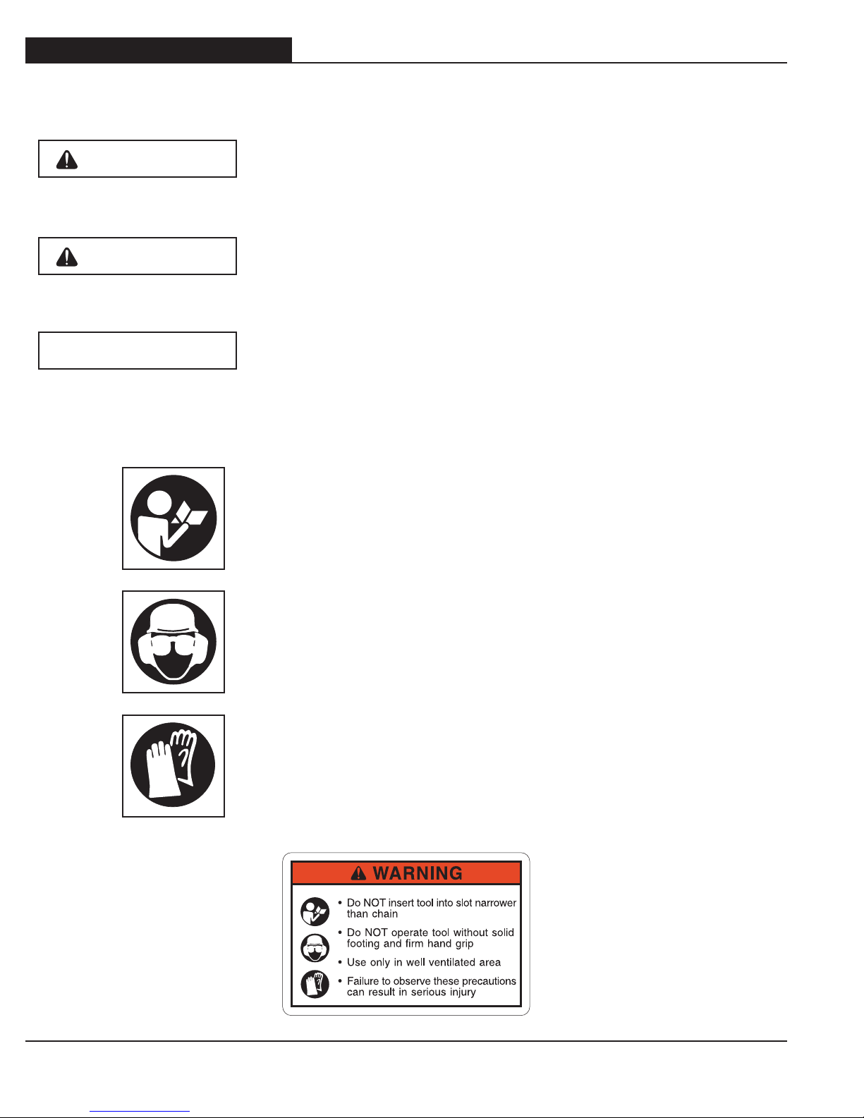
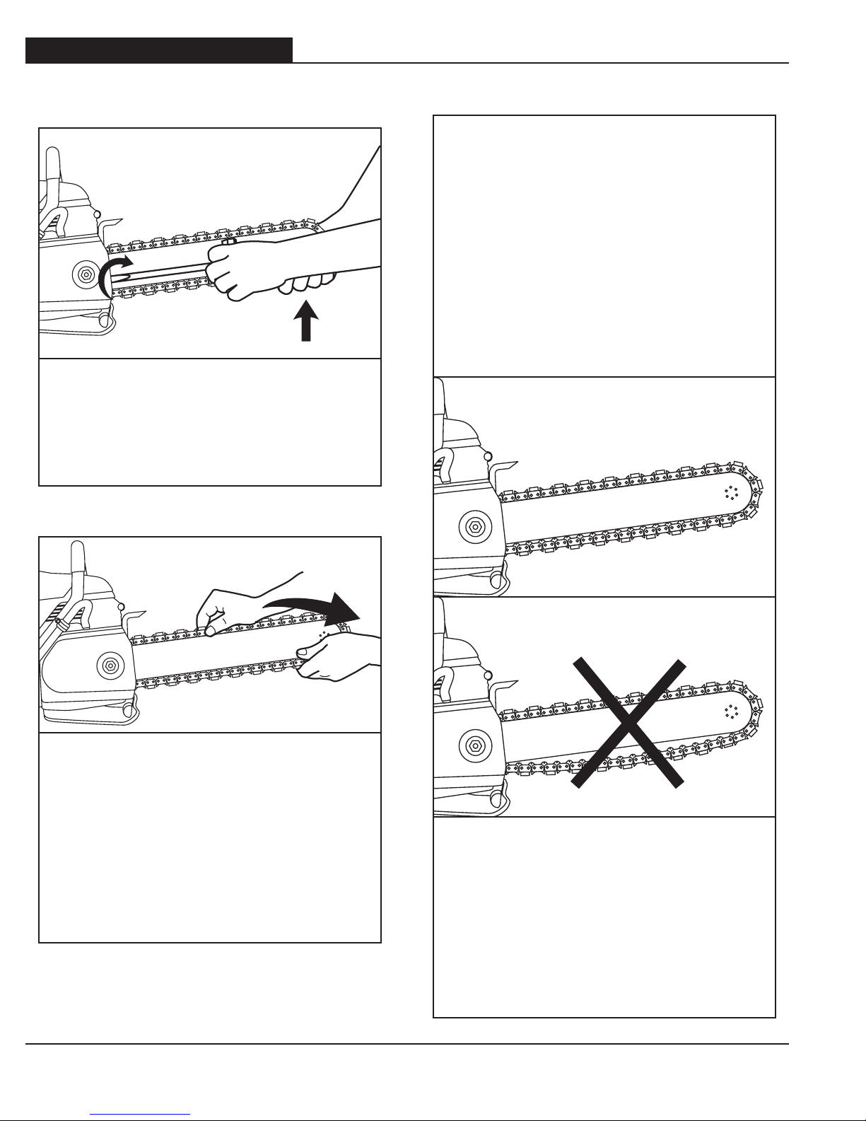
STEP 6
Before cutting, check for proper tension by
pulling the chain around the bar by hand. If
you cannot easily pull by hand, the chain is
too tight and needs to be loosened slightly.
CAUTION: Be aware that the guidebar
rails may develop sharp edges over time
so always pull the diamond chain by the
diamond segments.
STEP 5
Make sure all the drive links are inside
the guidebar groove then lift the bar nose
and tension the chain by turning the screw
clockwise.
CORRECT CHAIN TENSION
All chains have a tendency to stretch
when used. Diamond chains stretch more
than wood cutting chains because of the
abrasive materials they are cutting.
If the chain is too tight, a lot of the saw's
power goes into turning the chain rather
than into the cut. In extreme over-tightened
cases, the saw may not be able to turn the
chain at all. In addition, damage can occur
to the bar nose and premature stretch may
oc cur.
CHAIN TOO LOOSE
If the chain is too loose, it could come off
the bar, or it will allow the drive sprocket to
spin without turning the chain, which can
chew up drive links.
When a chain stretches to a point where
the drive links are hanging approximately
1/2 in (12 mm) to 3/4 in (18 mm) below the
bar, it is time to tension the chain.


(36) parts catalog")


