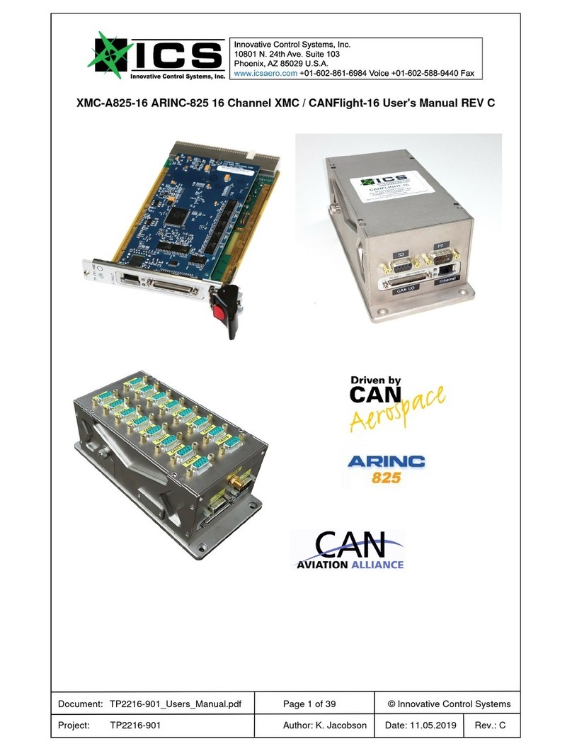
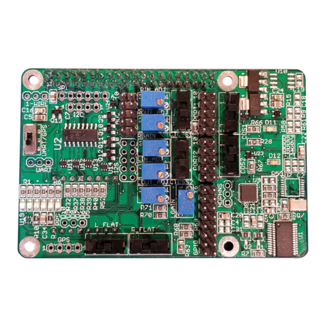
ICS DIO48S/AT-P Series User manual

DIO48S/AT-P Series
Product Manual
MANUAL NUMBER : 00650-526-1B

Page - iii
FOREWORD
This product manual provides information to install, operate and or program the referenced product(s)
manufactured or distributed by ICS Advent. The following pages contain information regarding the
warranty and repair policies.
Check our Web site (www.icsadvent.com) for technical information, manuals, and BIOS updates.
Technical assistance is also available at: 800-480-0044 (U.S.) or 858-677-0877 (international).
Customer Comments: If you experience any problems with this manual or just want to provide some
feedback, please send us a message using the online "Service Form" on our Web site (www.icsadvent.com)
under "Support." Detail any errors you find. We will correct the errors or problems as soon as possible and
post the revised manual in our online Support Library. Thank you.
The information in this document is provided for reference only. ICS Advent does not assume any liability
arising from the application or use of the information or products described herein. This document may
contain or reference information and products protected by copyrights or patents and does not convey any
license under the patent rights of ICS Advent, nor the rights of others.
Copyright © 2000, a California Corporation, 6260 Sequence Drive, San Diego, CA92121-4371. ICSAdvent
is a Registered Trademark of ICS Advent. All trademarks and registered trademarks are the property of
their respective owners. All rights reserved. Printed in the United States of America. No part of this publi-
cation may be reproduced, stored in a retrieval system, or transmitted, in any form or by any means, elec-
tronic, mechanical, photocopying, recording , or otherwise, without the prior written permission of the pub-
lisher.

Page - iv
This page intentionally left blank

Page - v
Shipments not in compliance with this Guarantee
and Limited Warranty Return Policy will not be ac-
cepted by ICS Advent.
Guarantee
A thirty day money-back guarantee is provided on all standard products sold. Special order products are
covered by our Limited Warranty, however they may not be returned for refund or credit. EPROMs,
RAM, Flash EPROMs or other forms of solid electronic media are not returnable for credit - but for
replacement only. Extended Warranty available. Consult factory.
Refunds
In order to receive a refund on a product for the purchase price, the product must not have been
damaged by the customer or by the common carrier chosen by the customer to return the goods and
the product must be returned complete (meaning all manuals, software, cables, etc.) within 30 days of
receipt and in an as-new and resalable condition. The Return Proceduremust be followed to assure
prompt refund.
Restocking Charges
Product returned after 30 days, and before 60 days, of the purchase will be subject to a minimum20%
restocking charge and charges for any damaged or missing parts. Products not returned within 60
days of purchase, or products which are not in an as-new and re-saleable condition, are not eligible
for credit return and will be returned to the customer.
Limited Warranty
Effective April 1, 1998, all products carry a 2-year limited warranty. Within two years of purchase,
ICS Advent will repair or replace, at our option, any defective product. ICS Advent will service the
warranty for all standard catalog products for the first two years from the date of shipment.
Please note: The 2-year warranty may not apply to special promotion items. Please consult the factory for
warranty verification.
The limited warranty is void if the product has been subjected to alteration, neglect, misuse, or abuse; if any
repairs have been attempted by anyone other than ICS Advent or its authorized agent; or if the failure is
caused by accident, acts of God, or other causes beyond the control of ICS Advent or the manufacturer.
Neglect, misuse, and abuse shall include any installation, operation, or maintenance of the product other than
in accordance with the user’s manual.
No agent, dealer, distributor, service company, or other party is authorized to change, modify, or extend the
terms of this Limited Warranty in any manner whatsoever. ICS Advent reserves the right to make changes
or improvements in any product without incurring any obligation to similarly alter products previously
purchased.

Page - vi
Return Procedure
For any Guarantee or Limited Warranty return, please contact ICS Advent's Customer Service at
800-480-0044 (U.S.) or 858-677-0877 (international) and obtain a Return Material Authorization (RMA)
Number. All product(s) returned to ICS Advent for service or credit must be accompanied by a Return
MaterialAuthorization (RMA) Number. Freight on all returned items mustbe prepaid by the customer who
is responsible for any loss or damage caused by common carrier in transit. Returns for Warranty must
include a Failure Report for each unit, by serial number(s), as well as a copy of the original invoice showing
date of purchase.
To reduce risk of damage, returns of product must be in an ICSAdvent shipping container. If the original
container has been lost or damaged, new shipping containers may be obtained from ICS Advent Customer
Service at a nominal cost.
ICS Advent owns all parts removed from repaired products. ICS Advent uses new and reconditioned parts
made by various manufacturers in performing warranty repairs and building replacement products.
If ICS Advent repairs or replaces a product, its warranty term is not extended.
ICSAdvent will normally return your replacement or repaired items via Second DayAir. Overnight delivery
or delivery via other carriers is available at an additional charge.
Limitation of Liability
In no event shall ICS Advent be liable for any defect in hardware, software, loss, or inadequacy of data of
any kind, or for any direct, indirect, incidental, or consequential damages in connection with or arising out of
the performance or use of any product furnished hereunder. ICSAdvent liability shall in no event exceed the
purchase price of the product purchased hereunder. The foregoing limitation of liability shall be equally
applicable to any service provided by ICSAdvent or its authorized agent.
Some Sales Items and Customized Systems are not subject to the guarantee and limited warranty.
However in these instances , any deviations will be disclosed prior to sales and noted in the original invoice.
ICS Advent reserves the right to refuse returns or credits on software or special order items.

Page - vii
Advisories
Three types of advisories are used throughout the manual to stress important points or warn of potential
hazards to the user or the system. They are the Note, the Caution, and theWarning. Following is an example
of each type of advisory:
Note: The note is used to present special instruction, or to provide extra information which may
help to simplify the use of the product.
CAUTION!
A Caution is used to alert you to a situation which if ignored may cause injury or
damage equipment.
WARNING!
AWarningisusedtoalertyouofasituationwhichifignoredwillcauseseriousinjury.
Cautions and Warnings are accented with triangular symbols. The exclamation symbol is used in all cautions
and warnings to help alert you to the important instructions. The lightning flash symbol is used on the left
hand side of a caution or a warning if the advisory relates to the presence of voltage which may be of
sufficient magnitude to cause electrical shock.
Use caution when servicing any electrical component. We have tried to identify the areas which may pose
a Caution or Warning condition in this manual; however, ICS Advent does not claim to have covered all
situations which might require the use of a Caution or Warning.
You must refer to the documentation for any component you install into a computer system to ensure proper
precautions and procedures are followed.

Page - viii
This page intentionally left blank

Page ix
Table of Contents
Chapter 1: Introduction ..............................................1-1
Description ........................................................... 1-1
Specification .......................................................... 1-3
Chapter 2: Installing the Card .........................................2-1
CD Installation ......................................................... 2-1
3.5-Inch Diskette Installation .............................................. 2-1
Directories Created on the Hard Disk ....................................... 2-2
Installing the Card ...................................................... 2-4
Chapter 3: Option Selection ..........................................3-1
Chapter 4: Address Selection .........................................4-1
Chapter 5: Software .................................................5-1
Setup ............................................................... 5-1
Chapter 6: Programming ............................................6-1
Developing Your Application Software ...................................... 6-1
Programming Example (Basic) ............................................ 6-4
Enabling/ Disabling I/O Buffers ............................................ 6-5
Change-of-state Interrupts ............................................... 6-6
Sharing Interrupts on the Isa Bus .......................................... 6-7
Chapter 7: Connector Pin Assignments ................................7-1
Appendix A: Programmable Peripheral Interface Data Sheets ............. A-1

Page x
List of Figures
Figure 1-1: DIO48S/AT-P Block Diagram ....................................... 1-4
Figure 3-1: DIO48S/AT-P Option Selection Map ................................. 3-2
List of Tables
Table 4-1: Standard Address Assignments for 286/386/486 Computers ............... 4-1
Table 6-1: Address Selection Table ........................................... 6-1
Table 6-2: Control Register Bit Assignment ..................................... 6-2
Table 6-3: Change-of-state-interrupt-enable Register ............................. 6-6
Table 7-1: Connector Pin Assignments ........................................ 7-1
Current Revision 1B
December 2000

Page 1-1
Manual 00650-526-1
Chapter 1: Introduction
Features
•48 Bits of Digital Input/Output.
•Interrupt Generation on Input Change of State.
•Change-of-state Interrupt Software Enabled in Six 8-Input Ports.
•All 48 I/O Lines Buffered on the Board.
•I/O Buffers Can Be Enabled/Disabled under Program Control.
•Four and Eight Bit Ports Independently Selectable for I/O.
•Pull-Ups on I/O Lines.
•+5V Supply Available to the User.
•Compatible with Industry Standard I/O Racks like Gordos, Opto-22, Potter & Brumfield,
etc.
Applications
•Automatic Test Systems.
•Laboratory Automation.
•Robotics.
•Machine Control.
•Security Systems, Energy Management.
•Relay Monitoring and Control.
•Parallel Data Transfer to PC.
•Sensing Switch Closures or TTL, DTL, CMOS Logic.
•Driving Indicator Lights or Recorders.
Description
The state of all inputs can be monitored and, if any one or more bits change state, a latched
interrupt request can be generated. Thus, it is not necessary to use software to continuously poll
the inputs to detect achange of state. The change-of-state interrupt is enabled by a software write
to an interrupt-enable register. Six bits in that register each control an eight-input port at one of
two type 8255-5 Programmable Peripheral Interface chips. The change-of-state interrupt latch can
be cleared by a software write.

DIO48S/AT-P Manual
Page 1-2
Manual 00650-526-1
Also, bit C3 at each 24-bit port can be used as an external interrupt to the computer if jumpers are
installed. When bit C3 goes high (edge triggering), an interrupt is requested. Interrupts from the
ports are OR'ed together and OR'ed with the change-of-state interrupt. Interrupts are directed to
levels #2 through #7, #10 through #12, #14 and #15 by jumper installation.
The DIO48S/AT-P card was designed for industrial applications and can be installed in 16-bit
ISA bus slots of IBM PC/XT/AT or compatible computers. Each I/O line is buffered and capable
of sourcing 15 mA or sinking 24mA (64 mA on request). The card contains two Programmable
Peripheral Interface chips type 8255-5 (PPI) to provide computer interface to 48 I/O lines. Three
8-bit ports A, B, and C. Each 8-bit port can be software configured to function as either inputs or
output latches. Port C can also be configured as four inputs and four output latches. Pull-ups on
the card assure that there are no erroneous outputs at power up until the card is initialized by
system software.
Tristate I/O line buffers (74LS245) are configured automatically by hardware logic for input or
output use according to direction assignment from acontrol register in the PPI. Further, if a
jumper is properly placed on the card, the tristate buffers are enabled/disabled under program
control. (See the Option Selection section to follow.)
I/O wiring connections are via 50-pin headers on the board. Two flat I/O cables connect
DIO48S/AT-P to termination. Also, this provides compatibility with OPTO-22, Gordos, Potter &
Brumfield, and all module mounting racks. Every second conductor of the flat cables is grounded
to minimize the effect of crosstalk between signals. If needed for external circuits, +5 VDC power
is available on each I/O connector pin 49. If you use this power, we recommend that you include a
1A fast-blow fuse in your circuits in order to avoid possible damage to the host computer or cable
in the event of a malfunction in those external circuits.
The DIO48S/AT-P occupies sixteen bytes of I/O address space. The base address is selectable via
aDIP switch anywhere within the range of 000-3F0 hex. An illustrated setup program is provided
with the DIO48S/AT-P card. Interactive displays show locations and proper settings of DIP
switches and jumpers to set up board address, interrupt levels, and interrupt enable. Also, sample
programs in Turbo-C and Turbo-Pascal are presented in the Software section of this manual.

Page 1-3
Manual 00650-526-1
Specification
Digital Inputs (TTL Compatible)
•Logic High: 2.0 to 5.0 VDC.
•Logic Low: -0.5 to +0.8 VDC.
•Input Load (Hi): 20 uA.
•Input Load (Lo): -200 uA.
Digital Outputs
•Logic High: 2.5 VDC min., source 15 mA.
•Logic Low: 0.5 VDC max., sink 24 mA.
(64 mA optional)
•Power Output: +5 VDC from computer bus (ext. 1A fast-blow fuse recommended).
•Power Required: +5 VDC at 300 mA typical.
•Size: 7.15" Long (182 mm)
Environmental
•Operating Temperature: 0 °C. to 60 °C.
•Storage Temperature: -50 °C. to +120 °C.
•Humidity: 0 to 90% RH, non-condensing.

DIO48S/AT-P Manual
Page 1-4
Manual 00650-526-1
Figure 1-1: DIO48S/AT-P Block Diagram

Page 2-1
Manual 00650-526-1
Chapter 2: Installation
The software provided with this card is contained on either one CD or multiple diskettes and must
be installed onto your hard disk prior to use. To do this, perform the following steps as
appropriate for your software format and operating system. Substitute the appropriate drive letter
for your CD-ROM or disk drive where you see d: or a: respectively in the examples below.
CD Installation
DOS/WIN3.x
1. Place the CD into your CD-ROM drive.
2. Type d:K to change the active drive to the CD-ROM drive.
3. Type installK to run the install program.
4. Follow the on-screen prompts to install the software for this card.
WIN95/98/NT
1. Place the CD into your CD-ROM drive.
2. The CD should automatically run the install program after 30 seconds. If the install
program does not run, click START | RUN and type d:install, click OK or press K.
3. Follow the on-screen prompts to install the software for this card.
3.5-Inch Diskette Installation
As with any software package, you should make backup copies for everyday use and store your
original master diskettes in asafe location. The easiest way to make a backup copy is to use the
DOS DISKCOPY utility.
In a single-drive system, the command is:
diskcopy a: a:K
You will need to swap disks as requested by the system.
In a two-disk system, the command is:
diskcopy a: b:K
This will copy the contents of the master disk in drive A to the backup disk in drive B.

DIO48S/AT-P Manual
Page 2-2
Manual 00650-526-1
To copy the files on the master diskette to your hard disk, perform the following steps.
1. Place the master diskette into a floppy drive.
2. Change the active drive to the drive that has the diskette installed. For example, if the
diskette is in drive A, type a:K.
3. Type installK and follow the on-screen prompts.
Directories Created on the Hard Disk
The installation process will create several directories on your hard disk. If you accept the
installation defaults, the following structure will exist.
[CARDNAME]
Root or base directory containing the SETUP.EXE setup program used to help you configure
jumpers and calibrate the card.
DOS\PSAMPLES: A subdirectory of [CARDNAME] that contains Pascal samples.
DOS\CSAMPLES: A subdirectory of [CARDNAME] that contains "C" samples.
Win32\language: Subdirectories containing samples for Win95/98 and NT.
WinRisc.exe
AWindows dumb-terminal type communication program designed for RS422/485 operation.
Used primarily with Remote Data Acquisition Pods and our RS422/485 serial communication
product line. Can be used to say hello to an installed modem.
ACCES32
This directory contains the Windows 95/98/NT driver used to provide access to the hardware
registers when writing 32-bit Windows software. Several samples are provided in a variety of
languages to demonstrate how to use this driver. The DLL provides four functions (InPortB,
OutPortB, InPort, and OutPort) to access the hardware.
This directory also contains the device driver for Windows NT, ACCESNT.SYS. This device
driver provides register-level hardware access in Windows NT. Two methods of using the driver
are available, through ACCES32.DLL (recommended) and through the DeviceIOControl handles
provided by ACCESNT.SYS (slightly faster).

Page 2-3
Manual 00650-526-1
SAMPLES
Samples for using ACCES32.DLL are provided in this directory. Using this DLL not only
makes the hardware programming easier (MUCH easier), but also one source file can be used
for both Windows 95/98 and WindowsNT. One executable can run under both operating
systems and still have full access to the hardware registers. The DLL is used exactly like any
other DLL, so it is compatible with any language capable of using 32-bit DLLs. Consult the
manuals provided with your language's compiler for information on using DLLs in your
specific environment.
VBACCES
This directory contains sixteen-bit DLL drivers for use with VisualBASIC 3.0 and Windows 3.1
only. These drivers provide four functions, similar to the ACCES32.DLL. However, this DLL is
only compatible with 16-bit executables. Migration from 16-bit to 32-bit is simplified because of
the similarity between VBACCES and ACCES32.
PCIThis directory contains PCI-bus specific programs and information. If you are not using a PCI
card, this directory will not be installed.
SOURCE
Autility program is provided with source code you can use to determine allocated resources at
run-time from your own programs in DOS.
PCIFind.exe
Autility for DOS and Windows to determine what base addresses and IRQs are allocated to
installed PCI cards. This program runs two versions, depending on the operating system. Windows
95/98/NT displays a GUI interface, and modifies the registry. When run from DOS or
Windows3.x, a text interface is used. For information about the format of the registry key, consult
the card-specific samples provided with the hardware. In Windows NT, NTioPCI.SYS runs each
time the computer is booted, thereby refreshing the registry as PCI hardware is added or removed.
In Windows 95/98/NT PCIFind.EXE places itself in the boot-sequence of the OS to refresh the
registry on each power-up.
This program also provides some COM configuration when used with PCI COM ports.
Specifically, it will configure compatible COM cards for IRQ sharing and multiple port issues.
WIN32IRQ
This directory provides ageneric interface for IRQ handling in Windows 95/98/NT. Source code
is provided for the driver, greatly simplifying the creation of custom drivers for specific needs.
Samples are provided to demonstrate the use of the generic driver. Note that the use of IRQs in
near-real-time data acquisition programs requires multi-threaded application programming
techniques and must be considered an intermediate to advanced programming topic. Delphi, C++
Builder, and Visual C++ samples are provided.

DIO48S/AT-P Manual
Page 2-4
Manual 00650-526-1
Findbase.exe
DOS utility to determine an available base address for ISA bus , non-Plug-n-Play cards. Run this
program once, before the hardware is installed in the computer, to determine an available address
to give the card. Once the address has been determined, run the setup program provided with the
hardware to see instructions on setting the address switch and various option selections.
Poly.exe
Ageneric utility to convert atable of data into an nth order polynomial. Useful for calculating
linearization polynomial coefficients for thermocouples and other non-linear sensors.
Risc.bat
A batch file demonstrating the command line parameters of RISCTerm.exe.
RISCTerm.exe
A dumb-terminal type communication program designed for RS422/485 operation. Used primarily
with Remote Data Acquisition Pods and our RS422/485 serial communication product line. Can
be used to say hello to an installed modem. RISCTerm stands for Really Incredibly Simple
Communications TERMinal.
Installing the Card
Before installing the card carefully read the Address Selection and Option Selection Sections of
this manual and configure the card according to your requirements. Use the special software
program called SETUP provided on CD with the card. It supplies visual aids to configure all areas
of the board.
Be especially careful with address selection. If the addresses of two installed functions overlap,
you will experience unpredictable computer behavior. If unsure what locations are available, you
can use the FINDBASE program provided on our CD to locate blocks of available addresses.
To Install the Card
1. Remove power from the computer.
2. Remove the computer cover.
3. Remove blank I/O backplate.
4. Install jumpers for selected options. See Option Selection
5. Select the base address on the card. See Address Selection
6. Loosen the nuts on the strain relief bar and swing top end free.
7. Install the card in an I/O expansion slot. If convenient, select a slot adjacent to a vacant
slot because this will make cable installation easier.
8. Thread the I/O cables, one by one, through the cutout in the mounting bracket and plug
them into the headers.
9. Smooth the cables as close as possible to the card and, while holding them close to the
surface of the card, swing the strain relief bar into position and tighten nuts.
10. Inspect for proper fit of the card and cables and tighten screws.
11. Replace the computer cover.

Page 2-5
Manual 00650-526-1
Input/Output connections are via two 50-pin headers on the card. A blank mounting bracket is
provided with units that are marked for CE (European) Certification and for these units
CE-certifiable cable and break-out methodology (cables connect to chassis ground at the aperture,
shielded twisted pair wiring, etc.) must be used. Also, it is important that the card mounting
bracket be properly screwed into place and that there be a positive chassis ground.

Page 3-1
Manual 00650-526-1
Chapter 3: Option Selection
Refer to the setup programs provided with the card. Also, refer to the Block Diagram on Page 1-4
and the Option Selection Map on the following page when reading this section of the manual.
External Interrupts are accepted on the I/O connector pin 9(bit C3). The Interrupt signal is
positive true. External Interrupts are enabled if the IEN jumper is installed. Interrupts are directed
to levels #2 through #7, #10 through #12, #14 and #15 by jumpers installed at locations labeled
IRQ2 through IRQ7, IRQ10 through IRQ12, IRQ14 and IRQ15 respectively.
Ameans of enabling or disabling the 74LS245 input/output buffers under program control is
provided at the jumper position labeled TST/BEN. When the jumper is in the BEN (Buffer
Enable) position, the I/O buffers are always enabled. When the jumper is in the TST (Tristate)
position, enabled/disabled state is controlled by acontrol register. (See the programming section of
this manual for a description.)
An LED, CR1, is provided at the top-center of the card to assist you in program development.
Each time an interrupt is generated, the LED will illuminate and remain on until the interrupt is
reset. If there is an immediate reset of the interrupt, it is likely that the LED will not remain on
long enough to be observed.
Note
A jumper must be installed in either the TST or the BEN position for the card to function.
There is awire jumper installed on the card at a position labeled WAIT. The associated circuitry
asserts aWAIT signal to the CPU in order to provide alonger write cycle. In this way, there is
assurance that the 8255 PPI. will have adequate time to accept inputs from the CPU in fast AT
computers. If this extra wait state will cause a problem in your application and if you deem it
non-essential, then this wire jumper may be clipped.
The foregoing are the only manual setups necessary to use the DIO48S/AT-P. Input/Output
selection and the change-of-state Interrupt Enable is done via software by writing to a control
register in each PPI as described in the Programming section of this manual.

DIO48S/AT-P Manual
Page 3-2
Manual 00650-526-1
Figure 3-1: DIO48S/AT-P Option Selection Map
Table of contents
Other ICS Computer Hardware manuals