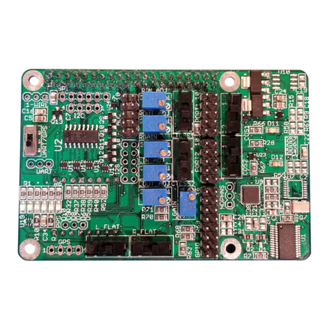
ICS PI-REPEATER-1X User manual

WWW.ICS-CTRL.COM USER MANUAL FOR HARDWARE REV 1.0 06-JUN-2019
PAGE 1
PI-REPEATER-1X
HARDWARE REVISION 1.0
1. WELCOME
Thank you for purchasing the PI-REPEATER-1X, the first repeater controller board designed to be
powered by the ubiquitous Raspberry Pi computer systems.
This little piece of hardware mates to the Raspberry Pi just like any other daughter card you may have
used for the Raspberry Pi, Arduino, or other development platform.
This system enables you to have a variety of control options for your station, including simplex, duplex,
echo-link, etc.
We use multiturn potentiometers for fine adjustment of the audio, offer hardware pre-emphasis
filtering, active high / active low selects for each COS / CTCSS input signal, and have inputs tolerant to
18Vdc for the signals coming from the radio.
This board will work with any software that is capable of interacting with the sound card (I2S), and
GPIO (I2C required)) for radio interfaces. We recommend getting started with SVXlink, but the choice
is ultimately yours! Feel free to experiment and decide which system best fits your requirements.

WWW.ICS-CTRL.COM USER MANUAL FOR HARDWARE REV 1.0 06-JUN-2019
PAGE 2
2. CONTENTS
TABLE OF CONTENTS
1. Welcome......................................................................................................................................... 1
2. Contents .........................................................................................................................................2
3. Hardware Introduction .................................................................................................................... 3
3.1 Duplex Port Configurable Features..............................................................................................4
3.2 Duplex Channel ...........................................................................................................................4
3.2.1 Input Audio Adjust................................................................................................................... 5
3.2.2 Flat audio select.......................................................................................................................6
3.2.3 Output amplifier gain ..............................................................................................................6
3.2.4 CTCSS Active High/Low........................................................................................................... 7
3.2.5 Port Connector & Pin 1 ............................................................................................................ 7
3.2.6 Output Audio Adjust................................................................................................................8
3.3 Built-in Audio CODEC..................................................................................................................8
3.4 Analog to Digital Converter.........................................................................................................9
3.5 GPIO Expansion...........................................................................................................................9
4 Getting Started with svxlink .......................................................................................................... 10
4.1 Hardware Pin numbers (SVXlink based) .................................................................................... 10
4.2 Advanced Configurations .......................................................................................................... 10
5 Schematics.................................................................................................................................... 10

WWW.ICS-CTRL.COM USER MANUAL FOR HARDWARE REV 1.0 06-JUN-2019
PAGE 3
3. HARDWARE INTRODUCTION
There are several features built into this little board that you should be aware of as they can easily be
missed when setting up the hardware for the first time. Your software selection may or may not
support all the features right out of the gate.
This board contains the following features which will be discussed in more detail in the following
sections
•1 Duplex Channel
oSelectable High/Low COS/COR
oSelectable High/Low CTCSS
oSelectable Flat Audio
oAdjustable audio input level
oAdjustable audio output level
•Built in audio (input/output)
•Analog to Digital Converter
•GPIO expansion
GPIO
PORT 1
ADC
AUDIO

WWW.ICS-CTRL.COM USER MANUAL FOR HARDWARE REV 1.0 06-JUN-2019
PAGE 4
3.1 DUPLEX PORT CONFIGURABLE FEATURES
The board supports 1 full duplex channel.
•Selectable High/Low COS/COR
oSelect the switch setting as shown in the following sections to select the polarity of
active signaling for your radio (typically active low)
•Selectable High/Low CTCSS
oSelect the switch setting as shown in the following sections to select the polarity of
active signaling for your radio (typically active low)
•Selectable Flat Audio
•Adjustable audio input level
•Adjustable audio output level
3.2 DUPLEX CHANNEL
FLAT AUDIO SELECT
CTCSS HI <-> LOW
Input AUDIO Adjust
Output AUDIO Adjust
Output Amplifier Gain
COS
LOW <-> HI
PIN 1

WWW.ICS-CTRL.COM USER MANUAL FOR HARDWARE REV 1.0 06-JUN-2019
PAGE 5
3.2.1 INPUT AUDIO ADJUST
The input audio adjust is used to adjust the amplitude of the volume coming from the receiver. This is
an 18 turn, 10kΩ potentiometer, multiple turns are required to effect a large change in amplitude, while
fractional turns yield fine resolution adjustments.
To restore the default audio position from the factory, this potentiometer should be rotated fully
counter clock-wise until it clicks, then three (3) full turns clockwise. Note some parts have a very soft
click, if you have one of these, ten full turns CCW will ensure it is set correctly before moving it
clockwise.
The input audio should be approximately 0.4 volts peak to peak as measured at R2.

WWW.ICS-CTRL.COM USER MANUAL FOR HARDWARE REV 1.0 06-JUN-2019
PAGE 6
3.2.2 FLAT AUDIO SELECT
This switch is used to select if the audio coming in requires the addition of a flat-audio filter (removes
pre-emphasis). When in the down position as shown, the filter is removed from the audio path.
To learn more about “Flat Audio” we recommend starting here:
http://www.repeater-builder.com/tech-info/flat-audio.html
3.2.3 OUTPUT AMPLIFIER GAIN
This is a multi-turn, 10kΩ potentiometer that can be used to adjust the output audio amplitude in the
buffer gain stage.
To restore the default audio position from the factory, this potentiometer should be rotated fully clock-
wise until it clicks. Note some parts have a very soft click, if you have one of these, ten full turns CW will
ensure it is set correctly.
When adjusting audio output, we suggest to only adjust this GAIN potentiometer and leave the
OUTPUT ADJUST potentiometer at the default position.

WWW.ICS-CTRL.COM USER MANUAL FOR HARDWARE REV 1.0 06-JUN-2019
PAGE 7
3.2.4 CTCSS ACTIVE HIGH/LOW
This switch is used to select the active on state for the CTCSS signal from the receiver radio. Typically,
this will be active low, but some radios output an active high signal. This input can be used for 3-18Vdc
signal levels.
While the board supports this signal, the SVXlink software does not support GPIO based CTCSS
detection yet. There are some tricks that can be done to make it work, but we recommend to just let
your receive radio handle this part of the detection.
3.2.5 PORT CONNECTOR & PIN 1
The duplex port comes out to a 2x5 male header. This header
is typically connected 1:1 into a DB9 Female connector, but
the user may also make a custom cable/adaptor for their own
equipment if desired.
Connector Selection: Due to the tight spacing of the board,
it is important to select mating connectors that do not exceed
the width of the male pin alignment blocks, or you risk
mechanical interference with the port 2 header. For custom
cables we suggest using connector block 952-2033-ND from
Digikey, or a similar variant. STANDARD IDC RIBBON
CABLE CONNECTORS WILL NOT FIT. Pre-crimped cables
are also available from the accessories page of our website.
Pin 1 is located in the bottom left corner as shown above in
section 3.1. When using ICS-CTRL provided DB9 connectors,
will correspond with the brown wire.
CONNECTOR PINOUT:
1- CTCSS ENCODE OUTPUT
2- CTCSS INPUT FROM RX
RADIO
3- PUSH TO TALK (OPEN
COLLECTOR)
4- AUDIO OUTPUT
5- AUDIO INPUT
6- GROUND
7- COS INPUT FROM RX RADIO
8- GROUND
9- GROUND
10-GROUND (DB9 SHELL)

WWW.ICS-CTRL.COM USER MANUAL FOR HARDWARE REV 1.0 06-JUN-2019
PAGE 8
3.2.6 OUTPUT AUDIO ADJUST
The output audio adjust is used to adjust the amplitude of the volume coming from the repeater board.
This is an multi turn, 10kΩ potentiometer, multiple turns are required to effect a large change in
amplitude, while fractional turns yield fine resolution adjustments.
This function is used to adjust the amplitude of the repeated audio being sent to your transmitter radio.
This output amplitude should be adjusted per the transmitter radio specifications.
To restore the default audio position from the factory, this potentiometer should be rotated fully
counter clock-wise until it clicks. Note some parts have a very soft click, if you have one of these, ten
full turns CCW will ensure it is set correctly.
When adjusting audio output, we suggest to only adjust the RGAIN potentiometer and leave this
potentiometer at the default position.
3.3 BUILT-IN AUDIO CODEC
The system contains a SGTL5000 Audio codec chip which provides stereo input and output capability so
you won’t require a USB sound card to have receive audio capability.
The stereo audio is split into 2 mono channels, this board uses 1, it uses the RIGHT audio channel only.

WWW.ICS-CTRL.COM USER MANUAL FOR HARDWARE REV 1.0 06-JUN-2019
PAGE 9
3.4 ANALOG TO DIGITAL CONVERTER
A MCP3208 is built into the system to provide
analog input capabilities with support for 8
channels with 12-bit resolution per channel.
Each channel is provided with some input
protection through a current limiting resistor and
a Zener diode. It is the user’s responsibility to
ensure the inputs are not over driven beyond a 5V
maximum input voltage to prevent damage to the
ADC unit.
vChannel A0 has a unique configuration to allow
for the use of a LM335 temperature sensor device.
It is recommended to use this channel last to
minimize potential confusion due to the unique
configuration.
When viewing the top of the board, the orange
arrow denotes pin 1 (A0) and increments up as
you move from right to left.
3.5 GPIO EXPANSION
As the repeater board consumes some of the
signals from the 40-pin header, an additional 8
pins are made available through a 16-pin header.
This header connects to PORT A on a MCP23017
IC. These pins are not protected from ESD or
overvoltage.
Caution should be exercised to ensure only 3.3V
logic levels are used to connect to these pins.
The GPIO expander provides the option to include
pull-up resistors should your circuit need these,
but are not turned on by default, you will be
responsible for configuration of these pins if used.
When viewing the top of the board as shown, the
orange arrow denotes pin 1 (GND) and counts up
as you move from right to left.

WWW.ICS-CTRL.COM USER MANUAL FOR HARDWARE REV 1.0 06-JUN-2019
PAGE 10
4GETTING STARTED WITH SVXLINK
Introduction: svxlink is a powerful open source controller software that works on many Linux based
platforms. We have partnered with Open Repeater Project to help users get the smoothest start-up
experience possible, but we remind you that ORP is intentionally kept very simplistic. This is to help
ensure you get a working setup easily; from there you can branch out and explore the more advanced
options from the command console.
To obtain the Open Repeater starter image, please visit www.openrepeater.com
4.1 HARDWARE PIN NUMBERS (SVXLINK BASED)
Port 1 PINS:
PTT –GPIO506 Active high
COS –GPIO26 Active Low
CTCSS –GPIO24 Active Low
Audio input –FE Pi Right Channel
Audio output –FE PI Right Channel
GPIO PINS:
GPA0 –GPIO496
GPA1 –GPIO497
GPA2 –GPIO498
GPA3 –GPIO499
GPA4 –GPIO500
GPA5 –GPIO501
GPA6 –GPIO502
GPA7 –GPIO503
See section 3.5 for details on identifying which pin is which for the GPIO.
4.2 ADVANCED CONFIGURATIONS
Svxlink has a lot of features and they are continuously evolving, so be sure to have a recent copy of the
manual for svxlink at hand. We will provide some examples for the most common setups encountered
as starting points. Sample configurations will be provided on our group.io group and our website as we
get them created.
If you have a specific hardware need, please make the request to the group.io Group for ICS-Controllers
or for SVXlink support, at the SVXlink support page respectively. Both pages have a good support
community and we monitor both groups actively.
As the SVXlink software updates frequently, it is best to ask there for software specific issues, but we
will do our best to help as well, but may not have the depth of knowledge that you will get from the
SVXlink community.
5SCHEMATICS
Please visit our downloads page for the schematics. Embedding them results in low quality copies that
are effectively useless.
Table of contents
Other ICS Computer Hardware manuals
Popular Computer Hardware manuals by other brands

EKF
EKF CompactPCI CCM-BOOGIE user guide

IBM
IBM BladeCenter S SAS RAID Controller Module Installation and user guide

EK-Quantum
EK-Quantum Momentum ROG Maximus XIII Hero D-RGB user guide

Freescale Semiconductor
Freescale Semiconductor TWR-S12GN32 quick start guide

DAQ system
DAQ system PCI-AIO02 user manual

Acrosser Technology
Acrosser Technology AR-B5630 user manual